
Related Manuals for SMC Networks TigerStack


Summary of Contents for SMC Networks TigerStack
-
Page 1: User Guide
TigerStack SwitchReady ™ Multi-Segment Stackable Ethernet Hubs Unmatched Bandwidth Scalability for Ethernet Workgroups User Guide... - Page 2 UIDE SMC’ IGER TACK AMILY OF THERNET March 1997 Pub. # 900.166 Rev. A Standard Microsystems Corporation 80 Arkay Drive Hauppauge, New York 11788...
- Page 3 All rights reserved. Printed in U.S.A. Trademarks: SMC and Standard Microsystems are registered trademarks; and TigerStack, TigerHub and EliteView are trademarks of Standard Microsystems Corporation. Other product and com- pany names are trademarks or registered trademarks of their respective holders.
-
Page 4: Limited Warranty
TigerStack Hubs (excluding Power Supply and Fan) ..Limited Lifetime TigerStack Power Supply and Fan ......Five Years... - Page 5 STANDARD WARRANTY SERVICE: Standard warranty service for hardware products may be obtained by delivering the defective product, accompanied by a copy of the dated proof of purchase, to SMC’s Service Center or to an Authorized SMC Service Center during the applicable warranty period. Standard warranty service for software products may be obtained by telephoning SMC’s Service Center or an Authorized SMC Service Center, within the warranty period.
-
Page 6: Table Of Contents
ABLE OF ONTENTS Compliances............About the Hubs..........Benefits .................. Features.................. Installing............Locating the Hub..............Equipment Checklist ............. Slide-in Modules..............Rack Mounting ..............Desktop or Shelf Mounting ..........Stacking.................. Connecting Power..............Connecting ............17 Making Network Connections ..........Connecting to Twisted-Pair Cabling........Connecting to Thin Coax Cabling ........ - Page 7 ABLE OF ONTENTS Specifications ..........43 TigerStack 3312TA..............TigerStack 3326TA..............TigerStack 3314T ..............TigerStack 3328T ..............TigerStack 3338TELCO............TigerStack 3306BC ..............TigerStack 3306FC ..............All TigerStack Hubs............... Stacking Cable ............... Cables............... 49 Types/Connectors ..............Cable Specifications .............. Extended Distance ..............
- Page 8 ABLE OF ONTENTS List of Figures TigerStack 3312TA..............TigerStack 3326TA..............Removing the Screws............Attaching the Brackets ............Installing the Hub in a Rack ..........Attaching the Adhesive Feet ..........Stacking the Hubs ..............Power Connector on Rear of Hub ........
- Page 9 ONTENTS 3326TA Front Panel LEDs ............. 3328T Front Panel LEDs............3328TELCO Front Panel LEDs ..........3306BC Front Panel LEDs ............. 3306FC Front Panel LEDs ............. RJ-45 Connector Pin Numbers..........25-Pair Telco Connector Pin Numbers......... List of Tables Crossover/Straight-Through Wiring Requirements....RJ-45 Fixed Crossover and Uplink Ports......
-
Page 10: Compliances
OMPLIANCES FCC A This equipment generates, uses, and can radiate radio frequency energy and, if not installed and used in accordance with the instruction manual, may cause interference to radio communications. It has been tested and found to comply with the limits for a Class A computing device pursuant to Subpart B of Part 15 of FCC Rules, which are designed to provide reasonable protection against such interference when operated in a commercial environment. - Page 11 DO NOT PLUG A PHONE JACK CONNECTOR INTO ANY OF THE RJ-45 PORTS. THIS MAY DAMAGE THE DEVICE. KUN FOR DATA. MÅ IKKE KOPLES TIL TELEFONNETTVERKET. SÓLO PARA TRANSFERIR DATOS. NO ENCHUFAR EN LA LÍNEA TELEFÓNICA. LES RACCORDEURS NE SONT PAS UTILISÉ POUR LE SYSTÈME TÉLÉFONIQUE.
-
Page 12: About The Hubs
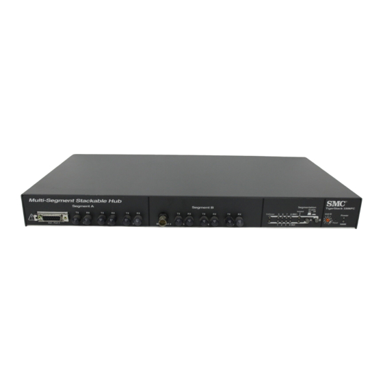
HAPTER BOUT THE Benefits ......2 Stackable ......2 Segmentable . -
Page 13: Benefits
Stackable A single TigerStack hub supporting a small workgroup can be expanded to a stack of eight units with up to 224 ports. Since the entire stack is still counted as one logical repeater (one of the four repeater hops permitted between any pair of PCs), TigerStack hubs make it easier to configure the network. - Page 14 SNMP-based ™ manager. Easy to Install TigerStack hubs can be easily installed in a 19-inch equipment rack or on a desktop or shelf. Available in a Wide Range of Models TigerStack hubs are available with 10BASE-T ports for twisted-...
-
Page 15: Tigerstack 3312Ta
BOUT THE • TigerStack 3306FC — a two-segment hub with six dual ST ports, one AUI port, and one BNC port • TigerStack 3328TELCO — a four-segment hub with 28 10BASE-T ports: 24 ports on two Telco connectors and four... -
Page 16: Features
BOUT THE Features All Models • Push-buttons or switches to segment each hub into inde- pendent networks • Front panel LEDs for “status-at-a-glance” troubleshooting: • Power — one per hub • NMM — one per hub • Collision — one per segment •... - Page 17 BOUT THE Models 3312TA and 3326TA The following additional features are provided by Models 3312TA and 3326TA: • Optional Redundant Power Unit to minimize downtime in the event of an internal power supply failure • Two expansion slots for optional slide-in 10BASE-T, BNC, fiber and AUI modules •...
-
Page 18: Installing
HAPTER NSTALLING Locating the Hub ..... . 8 Equipment Checklist ....8 Package Contents . -
Page 19: Locating The Hub
Equipment Checklist Package Contents Check that the following equipment is included in your package: • The TigerStack hub • Bracket Mounting Kit, containing two brackets and four screws for attaching the brackets to the hub • Four adhesive feet • This User Guide •... -
Page 20: Slide-In Modules
Slide-in Modules (Models 3312TA and 3326TA Only) SMC’s TigerStack 3312TA and 3326TA hubs are equipped with two expansion slots (port 7, port 14) for slide-in modules. AUI, 10BASE2, 10BASE-T and 10BASE-F modules are available. Port 7 is accessible from the front panel and port 14 is located on the rear of the hubs. -
Page 21: Rack Mounting
NSTALLING Rack Mounting Before rack mounting the hub, pay particular attention to the following factors: • Temperature: Since the temperature within a rack assem- bly may be higher than the ambient room temperature, check that the rack-environment temperature is within the operating temperature range specified in Appendix A. -
Page 22: Attaching The Brackets
NSTALLING Attaching the Brackets 3. Install the hub in the rack, using four rack-mounting screws (not provided). Installing the Hub in a Rack 4. If stacking hubs, install the remaining hubs in the rack, one atop the other. Then go to “Stacking” later in this chapter. 5. -
Page 23: Desktop Or Shelf Mounting
NSTALLING Desktop or Shelf Mounting 1. Attach the four adhesive feet to the bottom of the hub. Attaching the Adhesive Feet 2. Set the hub on a flat surface near an AC power source, making sure there are at least two inches of space on all sides for proper air flow. -
Page 24: Stacking
NSTALLING Stacking The hubs can be stacked as many as eight high, and all models can be mixed in the same stack, in any order or combination. Note: Although hubs can be stacked after being connected to a power source, it is not recommended as a safe net- working practice. -
Page 25: Stacking The Hubs
NSTALLING Stacking the Hubs... -
Page 26: Connecting Power
NSTALLING Connecting Power Note: It is recommended that the hubs be stacked before power is applied. To connect each hub to a power source: 1. Insert the power cable plug directly into the receptacle located at the back of the hub. Power Connector on Rear of Hub 2. - Page 27 Refer to Chapter 5, “Troubleshooting,” for more information about the LEDs. 4. For TigerStack 3312TA and 3326TA Only – If you have purchased one or more Redundant Power Units, connect them to these devices and to an AC power source now, fol-...
-
Page 28: Connecting
HAPTER ONNECTING Making Network Connections ... . . 18 Directly ......18 Via Transceiver . -
Page 29: Making Network Connections
Ethernet networks), they may be joined with two identical transceivers* and a length of the appropriate type of cable. For example, the TigerStack 3306BC hub (with its six BNC ports, one AUI port, and one 10BASE-T port) can be: • cascaded to another TigerStack 3306BC hub with two fiber... -
Page 30: Attaching A Transceiver To The Aui Port
For example, the TigerStack 3306FC (with its six fiber ports, one AUI port, and one BNC port) can be: • connected to any 10BASE-T adapter with a 10BASE-T trans-... - Page 31 ONNECTING The SMC 5 - 4 - 3 Rule When making connections, check to be sure that you do not exceed the IEEE guidelines for Ethernet networks. The easiest way is with the SMC 5 - 4 - 3 Rule given below. Note: This rule is completely consistent with the IEEE 802.3 specification.
-
Page 32: Connecting To Twisted-Pair Cabling
Additionally, one twisted-pair port in each segment on the 10BASE-T TigerStack hubs, and the lone twisted-pair port on the thin coax model, features a crossover enable/disable button — these are called uplink or switch-selectable crossover ports. -
Page 33: Crossover/Straight-Through Wiring Requirements
Straight-through Straight-through cable Straight-through Straight-through Crossover cable A list of the fixed and switch-selectable crossover (uplink) ports for each TigerStack model can be found in the following table: RJ-45 Fixed Crossover and Uplink Ports Port Numbers Model Fixed Crossover Uplink... -
Page 34: 10Base-T Connections
10BASE-T port on the hub. 3. If the device is an adapter and the TigerStack hub is in a wiring closet, attach the other end of the cable segment to a 10BASE-T modular wall outlet that is connected to the wiring closet (see “Wiring Closet Connections“... -
Page 35: Wiring Closet Connections Via Rj-45 Connectors
ONNECTING Wiring Closet Connections If the TigerStack hub has RJ-45 connectors: 1. Attach one end of a 50-pin Telco cable to the punch-down block in the wiring closet, and the other end to the patch panel on the rack. 2. Attach one end of the patch cable to the patch panel, and the other end to an open 10BASE-T port on the hub. -
Page 36: Wiring Closet Connections Via Telco Connectors
ONNECTING If the TigerStack hub has Telco connectors: 1. Attach one end of a 50-pin Telco cable to the punch-down block in the wiring closet 2. Attach the other end to the 50-pin connector on the TigerStack 3328Telco hub. Wiring Closet Connections via Telco Connectors... -
Page 37: Connecting To Thin Coax Cabling
To connect a TigerStack BNC port to a thin coax cable segment: 1. Attach the male end of a BNC T-Connector to the BNC port. -
Page 38: Connecting To Thick Coax Cabling
Each cable segment must be terminated at both ends by a 50 ohm N-Series terminator. One terminator must be grounded. To connect a TigerStack AUI port to a thick coax cable segment: 1. Attach a tap-type transceiver to the thick coax cable seg- ment. -
Page 39: Connecting To Fiber Cabling
ONNECTING Connecting to Fiber Cabling A fiber cable segment is used for point-to-point connections. When using two simplex cables: 1. Connect one end of the first cable to the hub’s Tx connector and the other end to the Rx connector on the other device. 2. -
Page 40: Segmenting
HAPTER EGMENTING The Segmentation Concept ....30 Isolating Segments ....31 Interconnecting Isolated Segments . -
Page 41: The Segmentation Concept
EGMENTING The Segmentation Concept Each TigerStack hub is composed of two or four repeater groups, with each group containing four or seven ports, de- pending upon the model. Thus, a stack eight high can have as many as 32 repeater groups. Initially, these groups are united into a single 10 Mbps segment via the inter-repeater bus which runs through the stacking cable. -
Page 42: Segmenting The Stack
Each workgroup can be attached to a different repeater group. Then the repeater groups can be isolated from the bus to form independent 10 Mbps networks (also known as colli- sion domains or segments). TigerStack Segments 1-32 Segmenting the Stack Microsegmentation is accomplished via front panel buttons or switches, depending on the model. -
Page 43: 3326Ta Segment Switches A, B, C, And D
EGMENTING 3326TA Segment Switches A, B, C, and D (the 3312TA has Two Switches: A and B) 3328T Segment Buttons A, B, C, and D (the 3314T has Two Buttons: A and B) 3328TELCO Segment Buttons A, B, C, and D 3306BC Segment Buttons A and B... -
Page 44: 3306Fc Segment Buttons A And B
Suppose you have a number of small, high-traffic workgroups that do need to share data and also need additional bandwidth. Once isolated from the bus, these workgroups can be intercon- nected through a switch. Switch Multiple 10 Mbps Uplinks Servers TigerStack Workstations Linking 10BASE-T Segments Through a Switch... -
Page 45: Segmenting The Hub
EGMENTING Segmenting the Hub The hub can be segmented either via hardware with the front panel switches (TA models) or buttons (all other models), or via software with EliteView or any other SNMP-based manager. Note: Unless the hardware lockout feature has been enabled via software, the latest action (either hardware or soft- ware) overrides the previous setting. -
Page 46: Segmenting The Hubs
EGMENTING Segmenting the Hubs Segment Button/Switch Functions Button Switch Function Stack Connects segment to the stack Isolate Isolates segment from the stack Joins hub segments to form larger collision domain... - Page 47 EGMENTING Procedure Models 3314T, 3328T, 3328TELCO, 3306BC, 3306FC 1. To isolate a segment, move the button labeled Segmentation Enable to the On position (out). 2. Either press the Reset button (using a small, pointed instru- ment) or power the hub off, then on again. Models 3312TA and 3326TA 1.
-
Page 48: Troubleshooting
HAPTER ROUBLESHOOTING Status/Diagnostic LEDs ....38 Testing the Installation ....41... -
Page 49: Status/Diagnostic Leds
ROUBLESHOOTING Status/Diagnostic LEDs The following front-panel LEDs aid in testing the hub and diag- nosing network problems: • One green Power LED • One bi-color NMM Status LED • One yellow Collision LED for each segment • One yellow Segment LED for each segment (Bi-color for Models 3312TA and 3326TA) •... -
Page 50: 3328T Front Panel Leds
ROUBLESHOOTING 3328T Front Panel LEDs 3328TELCO Front Panel LEDs 3306BC Front Panel LEDs 3306FC Front Panel LEDs... -
Page 51: Front Panel Leds
ROUBLESHOOTING The function of these LEDs is summarized in the table below: Front Panel LEDs Condition Status Power No AC power Green AC power on NMM not installed Blinking Green Power-on diagnostics being performed on NMM Green NMM has passed power-on diagnostics Blinking Yellow NMM failed power-on diagnostics Collision... -
Page 52: Testing The Installation
ROUBLESHOOTING Testing the Installation 1. Power up or reset the hub and check the LEDs (refer to “Connecting Power” in Chapter 2). 2. If the Power LED is not lit and there is no activity on the entire unit: • Check the connections between the hub, the power cord, and the wall outlet. -
Page 54: Specifications
TigerStack 3326TA ..... . 44 TigerStack 3314T ..... . . 45 TigerStack 3328T . -
Page 55: Tigerstack 3312Ta
PECIFICATIONS TigerStack 3312TA Order Numbers SMC3312TA (with US power cord) SMC3312TA EUR (with Continental power cord) SMC3312TA UK (with UK power cord) Ports 12 10BASE-T 2 expansion slots for optional AUI, 10BASE2, 10BASE-T and 10BASE-F modules Segments/Unit Weight 7.2 lbs. (3.27 kg) AC Input Power Maximum: 18.5 watts (23.0 watts with NMM) -
Page 56: Tigerstack 3314T
DC Input Power (from optional RPU) Maximum: +5 V @ 3 A, +12 V @ 700 mA (without NMM) +5 V @ 3.9 A, +12 V @ 800 mA (with NMM) TigerStack 3314T Order Numbers SMC3314T (with US power cord) -
Page 57: Tigerstack 3328Telco
4.7 lbs. (2.13 kg) AC Input Power Maximum: 22.7 watts (26.0 watts with NMM) Typical: 17.0 watts (21.5 watts with NMM) TigerStack 3328TELCO Order Numbers SMC3328TELCO (with US power cord) SMC3328TELCO EUR (with Continental power cord) SMC3328TELCO UK (with UK power cord) -
Page 58: Tigerstack 3306Fc
Weight 4.15 lbs. (1.88 kg) AC Input Power Maximum: 27.3 watts (33.88 watts with NMM) Typical: 21.84 watts (27.1 watts with NMM) All TigerStack Hubs Network Interface 10BASE-T RJ-45, 100 Ohm UTP cable (EIA/TIA categories 3, 4, 5) 10BASE2 BNC, 50 Ohm coax (RG-58A/U or RG-58C/U) 10BASE-F Dual ST, 62.5/125 micron core duplex fiber... -
Page 59: Stacking Cable
PECIFICATIONS Relative Humidity, non-condensing Operating: 0% to 90% Storage: 0% to 95% Power Supply Internal, auto-ranging transformer 100 to 240 VAC, 50 to 60 Hz Compliances Safety UL 1950 EN60950 (TÜV) CSA 22.2 No. 950 Emissions FCC Class A Canada Department of Communications, Class A EN55022 (CISPR 22) Class A VCCI Class 1 Immunity... -
Page 60: Cables
PPENDIX ABLES Types/Connectors ..... . 50 Cable Specifications ..... 51 Extended Distance . -
Page 61: Types/Connectors
ABLES Types/Connectors Cable Types and Connectors Cable Type Connectors 10BASE-T 100 ohm UTP, male 8-pin RJ-45 (Twisted-Pair) 22 - 26 AWG, or 50-pin Telco 0.4 - 0.6 mm, 2 pairs External male 15-pin, D-type, AUI Transceiver Drop Thick Coax 50 ohm Coax N-Series Thin Coax RG-58A/U or... -
Page 62: Cable Specifications
ABLES Cable Specifications Twisted-Pair Link Segment Specifications Type 100 ohm UTP (e.g., IBM Type 3 or AT&T DIW) Number of Pairs Max. Link Segment Length 328 ft. (100 m) Min. Link Segment Length 2.0 ft. (0.6 m) Max. Number of Attachments per Link Segment AUI Cable Specifications Type... -
Page 63: Thin Coax Cable Specifications
ABLES Thin Coax Cable Specifications Type RG-58A/U or RG-58C/U Coax Max. Segment Length 1,000 ft.* (305 m) Min. Distance Between 1.5 ft. (0.5 m) Devices Max. Number of Attachments per Cable Segment * See “Extended Distance.” Duplex Fiber Cable Specifications Type 50/125, 62.5/125, 80/125 100/140 micron core... -
Page 64: Extended Distance
The IEEE 802.3 10BASE2 specification defines the maximum length of a thin coax segment as 607 feet (185 m). However, TigerStack BNC ports support thin coax segments of up to 1,000 feet (305 m) in length with 50 ohm RG-58 cabling meet-... -
Page 65: 10Base-T Pin Assignments
ABLES 10BASE-T Pin Assignments Caution: Regulations regarding the connection of equipment to telephone networks vary from country to country. Check with your local telephone network supplier before using existing telephone wiring. An Ethernet twisted-pair link segment requires two pairs of wires. -
Page 66: 25-Pair Telco Connector Pin Numbers
25-Pair Telco Connector Pin Numbers The TigerStack 3328TELCO is equipped with two Telco connec- tors: the first for ports 1 to 6 and 8 to 13, and the second for ports 15 to 20 and 22 to 27. -
Page 67: 50-Pin Telco Pin Assignments
ABLES 50-Pin Telco Pin Assignments Assign- Assign- Ports ment* Numbers Ports ment* Number 1, 15 1, 15 1, 15 1, 15 2, 16 2, 16 2, 16 2, 16 3, 17 3, 17 3, 17 3, 17 4, 18 4, 18 4, 18 4, 18 5, 19... -
Page 68: Straight-Through Rj-45 Pin Assignments
ABLES Automatic Polarity Detection and Correction If a receive data pair has the “+” and “-” signals inadvertently switched, the hubs correct the signal inversion automatically, allowing the data path to operate correctly. Straight-Through Wiring If the twisted-pair link segment is to join two ports and only one of the ports has an internal crossover, the two pairs of wires must be straight-through. -
Page 69: Straight-Through 50-Pin Telco Pin Assignments
ABLES Straight-Through 50-Pin Telco Pin Assignments Port Device Equiv. RJ-45 Pin (Rx-) (Rx-) (Tx-) (Tx-) (Rx-) (Rx-) (Tx-) (Tx-) (Rx-) (Rx-) (Tx-) (Tx-) (Rx-) (Rx-) (Tx-) (Tx-) (Rx-) (Rx-) (Tx-) (Tx-) (Rx-) (Rx-) (Tx-) (Tx-) (Rx-) (Rx-) (Tx-) (Tx-) (Rx-) (Rx-) (Tx-) (Tx-) - Page 70 ABLES Straight-Through 50-Pin Telco Pin Assignments - Continued Port Device Equiv. RJ-45 Pin (Rx+) (Rx+) (Tx+) (Tx+) (Rx+) (Rx+) (Tx+) (Tx+) (Rx+) (Rx+) (Tx+) (Tx+) (Rx+) (Rx+) (Tx+) (Tx+) (Rx+) (Rx+) (Tx+) (Tx+) (Rx+) (Rx+) (Tx+) (Tx+) (Rx+) (Rx+) (Tx+) (Tx+) (Rx+) (Rx+)
-
Page 71: Crossover Rj-45 Pin Assignments
ABLES Crossover Wiring If the twisted-pair link segment is to join two ports and either both ports are labeled with an “X” or neither port is labeled with an “X,” a crossover must be implemented in the wiring. Crossover RJ-45 Pin Assignments End 1 End 2 1 (Tx+) -
Page 72: Crossover 50-Pin Telco Pin Assignments
ABLES Crossover 50-Pin Telco Pin Assignments Port Device Equiv. RJ-45 Pin (Rx-) (Tx-) (Tx-) (Rx-) (Rx-) (Tx-) (Tx-) (Rx-) (Rx-) (Tx-) (Tx-) (Rx-) (Rx-) (Tx-) (Tx-) (Rx-) (Rx-) (Tx-) (Tx-) (Rx-) (Rx-) (Tx-) (Tx-) (Rx-) (Rx-) (Tx-) (Tx-) (Rx-) (Rx-) (Tx-) (Tx-) (Rx-) - Page 73 ABLES Crossover 50-Pin Telco Pin Assignments - Continued Port Device Equiv. RJ-45 Pin (Rx+) (Tx+) (Tx+) (Rx+) (Rx+) (Tx+) (Tx+) (Rx+) (Rx+) (Tx+) (Tx+) (Rx+) (Rx+) (Tx+) (Tx+) (Rx+) (Rx+) (Tx+) (Tx+) (Rx+) (Rx+) (Tx+) (Tx+) (Rx+) (Rx+) (Tx+) (Tx+) (Rx+) (Rx+) (Tx+)
-
Page 74: Aui Pin Assignments
ABLES AUI Pin Assignments Note: Voltage Plus (VP) and Voltage Common (Vc) use a single twisted-pair in the AUI cable. AUI Pin Assignments Circuit Signal Name DO-A Data Out Circuit A DO-B Data Out Circuit B DO-S Data Out Circuit Shield DI-A Data In Circuit A DI-B... -
Page 76: Index
NDEX Cable segment IRL (Inter-Repeater Link) 20 AC line cord 15 populated 20 Adhesive feet 8, 12 unpopulated 20 Attaching Cascading hubs 18 adhesive feet 12 Changing AC line cord 15 BNC transceiver 19 Checklist, equipment 8 brackets 11 Collision power cord 15 domain, definition of 2 transceiver to AUI port 19... - Page 77 NDEX Desktop mounting 12 LAN switch 33 Diagnostics, power-on 15 LEDs Distance, extended 5, 26, 53 Collision 5, 16, 38-40 Drop cable, AUI 27 NMM 5, 15, 38-41 Duplex cable, fiber 28 Port Status 5, 16, 38-41 Power 5, 15, 38-41 power-up sequence 15 Equipment checklist 8 Segment 5, 16, 38-40...
- Page 78 NDEX Pin assignments Rejoining repeater groups 31 10BASE-T 54, 56-62 Removing screws 10 crossover 60-62 Repeater straight-through 57-59 hops 2 AUI 63 logical, definition of 2 Pin numbers Repeater groups RJ-45 54 definition of 30 Telco 55 interconnecting 2, 33 Point-to-point isolating 2, 31 connections 21, 28...
- Page 79 44-48 cable specifications 52 network interface 47 connections 26 stacking cable 48 terminating 26, 41 SQE switch 19 TigerStack ST connectors 28, 50 features 5 Stacking models 3, 4 cable 9, 13, 48 segments, number of 3, 4 hubs 2, 13, 14, 15...
- Page 80 FOR TECHNICAL SUPPORT, CALL: From U.S.A. and Canada (8:30 AM - 8:00 PM Eastern Time) (800) SMC-4-YOU; (516) 435-6250; (516) 434-9314 (Fax) From Europe (8:00 AM - 5:30 PM UK Greenwich Mean Time) 44 (0) 1344-420068; 44 (0) 1344-418835 (Fax) Bulletin Board Services (BBS) Modem settings: 9600,8,n,1 New York: (516) 434-3162 (connect speed up to 14,400)
Need help?
Do you have a question about the TigerStack and is the answer not in the manual?
Questions and answers