Table of Contents
Advertisement
Quick Links
Before using your air conditioner, please read
this manual carefully and keep it for future reference.
-
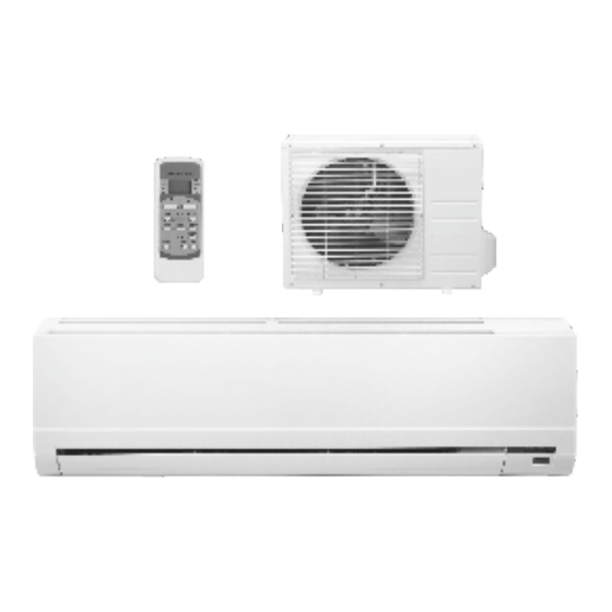
SPLIT TYPE
ROOMAIR CONDITIONER
Service Manual
Read This Manual
Please read this installation manual completely
before installing the product.
If the power cord is damaged, replacement work
shall be performed by authorised personnel only.
Installation work must be performed in accordance
with the national wiring Standards by authorised
personnel only.
Contact an authorised service technician for
repair, maintenance or installation of this unit.
Advertisement
Table of Contents

Related Manuals for Klimaire SPLIT TYPE ROOMAIR CONDITIONER


Summary of Contents for Klimaire SPLIT TYPE ROOMAIR CONDITIONER
-
Page 1: Service Manual
Before using your air conditioner, please read this manual carefully and keep it for future reference. SPLIT TYPE ROOMAIR CONDITIONER Service Manual Read This Manual Please read this installation manual completely before installing the product. If the power cord is damaged, replacement work shall be performed by authorised personnel only. -
Page 2: Table Of Contents
CONTENTS SAFETYPRECAUTIONS Warning ............................2 Caution ............................2 INSTALLATION INSTRUCTIONS Selecting installation place......................3 Accessories ..........................4 Indoor unit installation........................5 Outdoor unit installation........................9 REFRIGERANT PIPE CONNECTION Refrigerant pipe connection ......................10 ELECTRICALWORK Electrical work ..........................12 . TEST RUNNING Test running ...... -
Page 3: Warning
PRECAUTIONS Read the follow SAFETYPRECAUTIONS carefully before installation. Electrical work must be installed by a licensed electrician. Be sure to use the correct rating and main circuit for the model to be installed. Incorrect installation due to ignoring of the instruction will cause harm or damage, and the seri- ousness is classified by the following indications. -
Page 4: Installation Instructions
INSTALLATION INSTRUCTIONS Selecting installation place Read completely, then follow step by step. Indoor unit Do not expose the indoor unit t o heat or steam. Select a p lace where there are no obstacles in front or around the unit. Make sure that condensation drainage can be conveniently routed away. -
Page 5: Accessories
INSTALLATION INSTR UCTIONS Accessories Name ofAccessories Number Q ty Installation Plate ClipAnchor 5-8(depending on models) Self-tapping Screw AST3.9X25 5-8(depending on models) Seal (For cooling & heating models only) Drain Joint (For cooling & heating models only) Remote controller Self-tapping Screw B ST2.9X10 Optional Remote controller holder parts... -
Page 6: Indoor Unit Installation
INSTALLATION INSTR UCTIONS Indoor unit installation Correct orientation of I nstallation Plate 1. F it t he Installation Plate 1. Fit t he installation plate horizontally on structural parts of t he wall with spaces around the installation plate. 2. I f the wall i s made of brick, concrete or the like, drill f ive or eight 5 mm diameter holes Fig.4 in the wall. - Page 7 INSTALLATION INSTRUCTIONS 3. Dr aina ge Installa tion Drainage 1. Run the drain hose sloping downward. Do not install the drain hose as illustrated in Fig.7. 2. When connecting extension drain hose, insulate the connecting part of extension drain hose with Do not put the hose Do not form a rise a shield pipe, do not let the drain hose slack.
- Page 8 INSTALLATION INSTRUCTIONS Rememberthatiftheyaretightenedwithtoo little torquetheywillleakbutiftheyaretightened with toomuchtorque,thescrewconnectionsmay sufferdamage.Ifyoushouldnotbeconfident aboutconnectingtherefrigerantlineconnectors yourself,itisimperativethatyoucontactyour customerserviceteamorarefrigerationcontractor. Important! TheEQvalvesareonlydesignedfor one-timeinstallation.Theirsealcan notbe guaranteediftheyareinstalledonmorethanone Fig.9 occasion.Thiswillalsovoidthewarranty. 4.3 Connecting the refrigerant pipes to indoor unit 1. Do not remove the plastic seals from the indoor equipment and the appropriate refrigerant pipe until immediately before you connect them.
- Page 9 INSTALLATION INSTRUCTIONS Note: Route the package of pipes/hoses in the Rear-right piping direction of (rear)right or (rear)left. See Fig.13 . 5.Bundle the tubing, connecting cable with tape securely, evenly as shown in Fig.14. Because the condensed water from rear of the indoor unit is gathered in ponding box and is piped out of room.
-
Page 10: Outdoor Unit Installation
INSTALLATION INSTRUCTIONS Outdoor unit installation Outdoor unit 1. Outdoor installa tion pr ecaution Refrigerant pipe Select the location for installation(follow the previous Indoor unit notes on selecting the installation place). If the outdoor unit is higher thanthe indoor unit, make sure that a curve is made in the refrigerant pipe which is lower than the bottom edge of the ig.16 Curve... -
Page 11: Refrigerant Pipe Connection
REFRIGERANT PIPE CONNECTION 4. Connecting the r efriger ant pipe to outdoor unit CAUTION: For your safety, always wear goggles and work gloves when connecting the pipes. NOTE: To distinguish the connectors to be connected to the indoor unit and outdoor unit, the connectors of the refrigerant pipe has been labelled B , C and D . - Page 12 REFRIGERANT PIPE CONNECTION Coup ling size (last 2 part numb ers) Poun d-for ce foot( 1bf-f t) Newt on mete r(N-m ) Kilog ram- force mete r(kgf -m) -06(9.5mm dash size) 18 - 20 24.4 - 27.1 2.4 - 2.7 -08(12.7mm dash size) 40.6 - 47.4 4.1 - 4.8...
-
Page 13: Electricalwork
ELECTRICAL WORK Electrical w Cover Electric safety regulations for the initial Installation 1. If there is serious safety problem about the power Screw supply, the technicians should refuse to install the air conditioner and explain to the client until the problem is solved. - Page 14 ELECTRICAL WORK 4. Ensure the colour of wires of outdoor unit and the terminal Nos. are the same to the indoor s respectively. 5. Wrap those cables not connected with terminals with insulation tapes, so that they will not touch any electrical components.
-
Page 15: Test Running
TEST RUNNING CAUTION CAUTION CAUTION CAUTION After the confirmation of the above conditions, prepare the wiring as follows: Never fail to have an individual power circuit specifically for the air conditioner.As for the method of wiring, be guided by the circuit diagram posted on the inside of control cover. - Page 16 2190 NW 89 Place - Doral, FL 33172 USA Tel: (305)594-4972 Fax (305) 675-2212 www.klimaire.com sales@klimaire.com The design and specifications are subject to change without prior notice for product improvement. Consult with the sales agency or manufacturer for details.
Need help?
Do you have a question about the SPLIT TYPE ROOMAIR CONDITIONER and is the answer not in the manual?
Questions and answers