Table of Contents
Advertisement
Quick Links
Advertisement
Table of Contents

Related Manuals for Extech Instruments 382357


Summary of Contents for Extech Instruments 382357
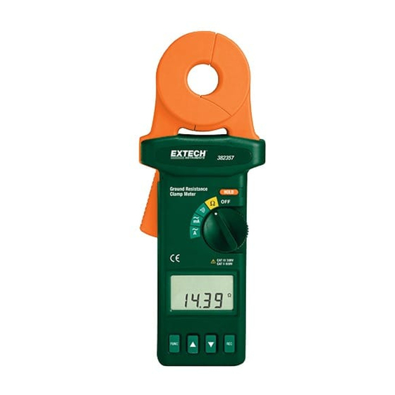
- Page 1 USER MANUAL Ground Resistance Clamp‐On Tester MODEL 382357 ...
-
Page 2: International Safety Symbols
Introduction Congratulations on your purchase of Extech’s 382357 Ground Resistance Tester. This Clamp‐on device allows the user to measure ground resistance without the use of auxiliary ground rods. This device can only be used on multi‐grounded systems. It is not necessary to disconnect the ground under test. This meter is shipped fully tested and calibrated and, with proper use, will provide years of reliable service. Please visit our website (www.extech.com) to check for the latest version of this User Guide, Product Updates, and Customer Support. Safety Only qualified technicians should operate this meter. Use extreme caution when operating the meter near energized electrical equipment. Do not attempt to use this meter to twist or pry the ground electrode or ground wire away from grounded equipment. All metal objects or wires connected to the electrical system under test should be assumed to be lethal until tested. Grounded systems are no exception. Ensure that the batteries are inserted correctly in the battery compartment. Remove the batteries from the meter if the meter is to be stored for long periods. WARNING: If the meter is used in a manner not specified by the manufacturer, the built in protections provided by the meter may be impaired. International Safety Symbols This symbol, adjacent to another symbol or terminal, indicates the user must refer to the manual for further information. This symbol, adjacent to a terminal, indicates that, under normal use, hazardous voltages may be present 382357‐EU‐EN V2.4 2/13 ... - Page 3 Description Jaw Assembly Hold Button Rotary Selector Switch LCD Display Record Button ▼(decrement) Button ▲(increment) Button Function Button Measurement Trigger Display Symbols REC: Indicates data logging in progress NO. Indicates the READ function : Clamp jaws are not fully closed NOISE: Excessive noise on the ground conductor or rod ))): Hi Lo alarm position Function or Record display Ω: Ohms (resistance measurement) mA: milli‐amperes, Amperes (current measurements) H: Hold function activated Main display : Low Battery Auto Power Off 382357‐EU‐EN V2.4 2/13 ...
-
Page 4: Operation
Operation Note: Ensure that the jaws are fully closed before testing. Note: DO NOT clamp on to any conductor or open the clamp jaws during the start‐up self‐ calibration (self‐cal is identified by the LCD counting down from CAL7 to CAL1). Ground Resistance Measurements Open the clamp jaws and check that all surfaces are clean and free of dust, dirt, or any foreign substances. Clean if necessary. Forcefully snap the clamp jaws open and closed several times. Turn the meter on by moving the rotary switch to the ohms position. DO NOT interrupt the start up procedure by opening the clamp jaws or clamping around a conductor. During self‐calibration, the meter will display CAL5, CAL4, CAL3, CAL2 and CAL1. Once the start‐up calibration procedure is completed, the meter will sound a beep. Clamp on to an electrode or ground rod and read the value of ground resistance on the display. Ground / Leakage Current Measurement Turn the meter on by moving the rotary switch to the mA or A position. Clamp on to the electrode or conductor Read the value of leakage current displayed on the LCD. HOLD Press the HOLD button to freeze the reading in the display. H will appear in the display. Press HOLD again to exit the function. 382357‐EU‐EN V2.4 2/13 ... -
Page 5: High And Low Alarm
High and Low Alarm Turn the meter on by moving the rotary switch to the ))) position. Press the FUNC button to view and adjust the “HI” alarm value. Press ▲ or the ▼ button to increase or decrease the value. Hold down the button to increase the speed of adjustment. The value can be incremented from 0 to 1500 ohms and then OL (overload). The value will roll over to 0 after OL is displayed. Once the desired value is set, press the FUNC button a second time to view and adjust the “LO” alarm value. Press the FUNC button three more times to exit the setting mode. The meter will now compare the measured resistance value with the high and low limits when the meter is set to the ))) position. If the reading is larger than the HI value, the meter will beep and display “HI” on the LCD. If the reading is lower than the LO value, the meter will beep and display “LO” on the LCD. Data Logging Setting the Sampling Time Press the FUNC button three times until the “SEC” symbol appears in the LCD display. The sampling rate is now displayed in seconds. Press the▲ or the ▼ button to increase or decrease the value. The value can be incremented from 0 to 255 seconds. Once the desired value is set, press the FUNC button several times until the characters in the upper row of the LCD disappear. Recording Data Press the REC button to start recording data at the specified sampling rate. The “REC” symbol will appear on the top of the LCD display. To stop recording, press the REC button. The “REC” symbol will no longer be displayed on the LCD. NOTE: Data logging will automatically stop if the memory is filled (116 records), or if the meter detects a low battery condition. NOTE: If the sampling interval is set to 0, only one sample will be recorded. To record another sample, press REC again. 382357‐EU‐EN V2.4 2/13 ... -
Page 6: Recalling Stored Data
Recalling Stored Data Press the FUNC button four times until the “NO.” symbol is displayed on the LCD. The current record number will be displayed in the top row and the data will be displayed below it. Press the ▲ or the ▼ button to step through and read the data in the next memory location. Holding down the button will increase the speed of the incrementing value. Clearing Data Memory With the meter powered off, press and hold down the REC button while turning the meter on. The “CL” symbol will appear on the display indicating that memory has been cleared. 382357‐EU‐EN V2.4 2/13 ... -
Page 7: Measurement Principles
,... where: If R and R , R , R …R , are approximately the same, and n is large (200, for example), then R will be much less then R and may possibly approach zero. Example: If R and R , R , R …R are all 10 respectively and n = 200, then R by calculation equals: 382357‐EU‐EN V2.4 2/13 ... - Page 8 Turn the meter switch to the Ohm function. Once the start‐up calibration procedure is completed clamp on to an electrode or ground rod. Allow several seconds for the meter to settle and then note the reading. Cellular Transmission Towers WARNING: Use extreme care when making measurements around transmission towers; High Voltage may be present. The ground conductor should be located at the base of the tower, but your configuration may be different. Locate the ground conductor Clamp around the ground conductor. You should place the clamp before any splices, bonds or other splits in the ground system. Read the measured reading. Primary Ground Conductor Transmission Tower Cement Pad Branch Ground Conductors 382357‐EU‐EN V2.4 2/13 ...
-
Page 9: Troubleshooting
Service Entrance Note: Multiple ground rods, multiple grounds i.e. ground rod(s) and water pipe grounds, or a combination may be present depending on the particular situation. In these situations it is necessary to make your measurements between the service‐entrance neutral and all subsequent ground points. Distribution Panel Water Pipe Ground Troubleshooting Snap the jaws open and closed two or three times before turning the meter on Do not clamp on to any device during the power‐up initialization sequence. Snap the jaws two or three times after clamping on to the ground electrode or rod. Slight amounts of drift may occur at high resistance measurements; this is normal and should not be cause for concern. Blank display or any failure mode Replace the battery before proceeding. Start‐up Initialization Failure The start‐up calibration will continue indefinitely if the jaws are open or dirty. Check that the jaws’ mating surfaces are clean. Do not open the jaws while the initialization sequence is running. Noise on the Ground Electrode or Rod If noise is present (over 3A or 30V) on the ground electrode or rod, the word “NOISE“ will appear on the display and readings can no longer be considered accurate. Before the meter can be used accurately, the noise problem must be addressed. 382357‐EU‐EN V2.4 2/13 ... - Page 10 Reference Test Loop The reference test loop is a set of resistors that provides a means to check the performance of the meter. Open the measurement jaws and check that the mating surfaces are clean and free of dust, dirt, or any foreign substances. Clean if necessary. Clamp the meter around the reference loop as shown in the diagram. Give the meter a few seconds to settle and read the measurement. The meter should display approximately the same value as marked on the reference loop, taking into consideration the accuracy listed in the specification chart. If the readings are not similar to what is marked on the reference loop, consult the Trouble Shooting and Maintenance sections of this manual. 382357‐EU‐EN V2.4 2/13 ...
-
Page 11: Maintenance
Maintenance General Care Store the ground resistance tester and reference loop in its case when not in use. A damp cloth may be used to clean any surface dirt from the meter. Never use harsh detergents, abrasives, solvents, or cleaners on the meter. Battery Replacement When the low battery symbol appears on the display, replace the meter’s 9V battery. Use a high quality alkaline battery whenever replacement becomes necessary. Remove the two rear screws and open the meter housing. Replace the battery, close the meter housing, and affix the two rear screws. Never dispose of used batteries or rechargeable batteries in household waste. As consumers, users are legally required to take used batteries to appropriate collection sites, the retail store where the batteries were purchased, or wherever batteries are sold. Disposal: Do not dispose of this instrument in household waste. The user is obligated to take end‐of‐life devices to a designated collection point for the disposal of electrical and electronic equipment. Other Battery Safety Reminders o Never dispose of batteries in a fire. Batteries may explode or leak. o Never mix battery types. Always install new batteries of the same type. Clamp Jaw Maintenance The jaws may be brushed clean with a toothbrush or similar soft‐bristled brush. Care must be taken to ensure that the contact fins are not bent or deformed, as this will affect the operation of the meter. 382357‐EU‐EN V2.4 2/13 ... -
Page 12: General Specifications
Datalogging sample rate 1 to 255 seconds Power supply One (1) 9V battery Power consumption 40mADC Battery Life 3000 measurements Temp. Coefficient 0.15 times the specified accuracy per C from 4 to 18 C (39 to 64ºF) and 28 to 50 C (82 to 122ºF) Current Overload Protected to 100A Continuous; 200A for less than 5 seconds (50/60Hz) Range selection Automatic ranging Safety Meets the requirements for IEC1010‐1 Category III 300V and Category II 600 V Operating conditions to 50 C (32 to 122 F) with < 85% RH Storage conditions ‐20 to 60 C (‐4 to 140 F) with < 75% RH Dimensions 257 x 100 x 47mm (10.1 x 3.9 x 1.9”) Weight 1.4lbs (640g) Accessories Resistance check plate, 9V battery, & carrying case 382357‐EU‐EN V2.4 2/13 ... - Page 13 0.300 to 1.000mA ± (2.0% ± 0.05mA) 1.00 to 10.00mA ± (2.0% ± 0.03mA) Autoranging 10.0 to 100.0mA ± (2.0% ± 0.3mA) 100 to 1000mA ± (2.0% ± 0.3mA) 0.20 to 4.00A ± (2.0% ± 0.03A) Manual range 4.00 to 30.00A ± (3.0% ± 0.03A) Notes: 50/60Hz bandwidth, True RMS sensing, Crest Factor < 3.0 High and Low Alarm (programmable) Range Resolution High Alarm 0‐1510 Low Alarm 0‐1510 Copyright © 2013 FLIR Systems, Inc. All rights reserved including the right of reproduction in whole or in part in any form ISO‐9001 Certified www.extech.com 382357‐EU‐EN V2.4 2/13 ...
Need help?
Do you have a question about the 382357 and is the answer not in the manual?
Questions and answers