Table of Contents
Advertisement
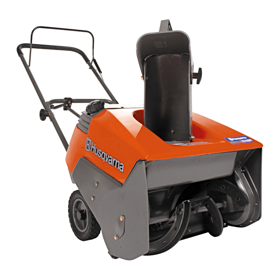
Operator's Manual
Models
521SSE
521SSR
Read and keep this book for future reference.
This book contains important information on
SAFETY, ASSEMBLY, OPERATION, AND MAINTENANCE.
PRODUCT INFORMATION
The owner must be certain that all the
product information is included with the unit.
This information includes the INSTRUCTION
BOOKS, the REPLACEMENT PARTS and the WARRANTIES.
This information must be included to make sure state laws and
other laws are followed.
1740274
TP 100-4350-01-SW-R
16
Advertisement
Table of Contents

Related Manuals for Husqvarna 521SSE


Summary of Contents for Husqvarna 521SSE
- Page 1 Operator’s Manual Models 521SSE 521SSR Read and keep this book for future reference. This book contains important information on SAFETY, ASSEMBLY, OPERATION, AND MAINTENANCE. PRODUCT INFORMATION The owner must be certain that all the product information is included with the unit.
-
Page 2: Responsibility Of The Owner
Congratulations on your purchase. This Snowthrower has been designed, engineered and manufactured to give you the best possible dependability and performance. However, like all mechanical products, your machine will occasionally require adjust- ment and maintenance. This handbook should be read before operating or performing and adjustments on your machine. The instructions in this Owner’s Manual are written for a person with some mechanical ability. -
Page 3: Rules For Safe Operation
RULES FOR SAFE OPERATION This manual contains safety information to make you aware of the hazards and risks associated with snow throwers, and how to avoid them. The snow thrower is designed and intended for removal of snow, and should not be used for any other purpose. It is important that you read and understand these instructions, and anyone operating the equipment read and understand these instructions. -
Page 4: Safe Operation Practices
RULES FOR SAFE OPERATION WARNING: This machine is capable of amputating hands and feet and throwing objects. Read these safety rules and follow them closely. Failure to obey these rules could result in loss of control of unit, severe per- sonal injury or death to you, or bystanders, or damage to property or equipment. - Page 5 RULES FOR SAFE OPERATION 12.Never operate the machine at high transport speeds on slippery surfaces. Look behind and use care when operat- ing in reverse. 13.Disengage power to the collector/impeller when snow- thrower is transported or not in use. 14.Use only attachments and accessories approved by the manufacturer of the snowthrower (such as cabs, tire chains, etc..).
-
Page 6: Table Of Contents
RULES FOR SAFE OPERATION HAZARD SYMBOLS AND THE MEANINGS OPERATING SYMBOLS AND THEIR MEANINGS SAFE OPERATION PRACTICES SAFETY DECALS OWNER’S INFORMATION WARRANTIES ASSEMBLY PARTS BAGS CONTENTS: TOOLS REQUIRED FOR ASSEMBLY HOW TO REMOVE THE SNOW THROWER FROM THE CARTON HOW TO INSTALL THE CHUTE CRANK HOW TO ASSEMBLE THE HANDLE HOW TO INSTALL THE CHUTE OPERATION... -
Page 7: Safety Decals
WARNING: If safety decals are dam- aged or missing, replace immediately. Look for this symbol to indicate important safe- ty precautions. This symbol indicates: “Atten- tion! Become Alert! Your Safety Is At Risk.” Before operation of your snowthrower, read the safety de- cals as shown on your snowthrower. -
Page 8: Owner's Information
SECTION 2: HUSQVARNA’S OBLIGATIONS UNDER THE WARRANTY Husqvarna will repair or replace defective components without charge for parts or labor if a component fails because of a defect in material or workmanship during the warranty period. - Page 9 It is the Owner’s and Retailer’s responsibility to make certain that the Warranty Registration Card is properly filled out and mailed to Husqvarna Forest & Garden Company. This card should be mailed within ten (10) days from the date of purchase in order to confirm the warranty and to facilitate post-sale service.
-
Page 10: Assembly
PARTS BAGS CONTENTS: 1 − 2.6 ounces 2−cycle oil 1 − Owner’s Manual TOOLS REQUIRED FOR ASSEMBLY 1 − Knife 1 − Pliers 2 − Adjustable Wrenches 1 − Flat Screwdriver HOW TO REMOVE THE SNOW THROWER FROM THE CARTON 1. -
Page 11: How To Assemble The Handle
HOW TO ASSEMBLE THE HANDLE 1. Remove the packing material from the upper and lower handles. 2. Loosen the knobs on each side of the handle. (See Figure 3) 3. Raise the upper handle to the operating position (see Figure 4). Hold the upper handle apart to prevent scratching the lower handle. - Page 12 Make sure the fuel tank is filled with the correct mixture (50:1 ratio) of gasoline and Husqvarna 2 Cycle oil. n Become familiar with the location of all controls and under- stand their function.
-
Page 13: Operation
KNOW YOUR SNOWTHROWER READ THIS OWNER’S MANUAL AND SAFETY RULES BEFORE OPERATING YOUR SNOWTHROWER. Compare the illustrations with your SNOWTHROWER to familiarize yourself with the location of various controls and adjustments. Save this manual for future reference. Auger Drive Lever Chute Deflector Discharge Chute Auger... -
Page 14: Snowthrower Operation
SNOWTHROWER OPERATION The most effective use of the snowthrower will be established by experience, taking into consideration the terrain, wind conditions and building location which will determine the direction of the discharge chute. NOTE: Do not discharge snow toward a building as hidden objects could be thrown with sufficient force to cause damage. -
Page 15: Before Starting The Engine
Mix gasoline and oil as follows: 1. Pour one (1) U.S. quart of fresh, clean, unleaded auto- 2. Add 2.6 ounces of clean, high quality, Husqvarna two− 3. Install the fuel cap onto the gasoline container. Vigor- 4. Add an additional three (3) U.S. quarts of gasoline to ning, when it is hot, or when snow thrower is in an enclosed area. -
Page 16: How To Stop The Engine
BEFORE STARTING THE ENGINE 1. Before you service or start the engine, familiarize yourself with the snow thrower. Be sure you understand the func- tion and location of all controls. 2. Be sure that all fasteners are tight. HOW TO START THE ENGINE The following starting instructions include directions for both Recoil Start and Electric Start engines. -
Page 17: How To Clear A Clogged Discharge Chute
Use a clean-out tool to remove snow or debris. WARNING: Blockage must be cleared only after shutting off the snow blower and only with a clean-out tool, not by hand. 10. After each snow throwing job, allow the engine to run for a few minutes. -
Page 18: Service Recommendations
SERVICE RECOMMENDATIONS PROCEDURE Tighten all screws and nuts Lubricate Chute Control Flange Lubricate Auger Bail Check Auger Drive Cable Adjustment (See Cable Adjustment) Check Drive Belt The warranty on this snowthrower does not cover items that have been subjected to operator abuse or negligence. To receive full value from the warranty, operator must maintain snowthrower as instructed in this manual. -
Page 19: How To Lubricate The Idler Arm
SERVICE RECOMMENDATIONS HOW TO LUBRICATE THE IDLER ARM CAUTION: DO NOT get oil on the belt or pulleys. This will cause the belt to slip and experience premature failure. 1. Remove the screws from the belt cover (see Figure 12). Remove the belt cover. -
Page 20: Maintenance
HOW TO ADJUST THE BELT TENSION IMPORTANT: When you release the auger bail, the au- ger must stop rotating. If the auger does not stop, ad- just the belt tension as follows: 1. Disconnect the spark plug wire from the spark plug. 2. -
Page 21: How To Free The Auger Cable
HOW TO REPLACE THE SCRAPER BLADE 1. Use adjustable wrenches to remove the fasteners that secure the scraper blade (Figure 16). 2. Install a new scraper blade and secure with the fasteners removed in step 1. HOW TO FREE THE AUGER CABLE IMPORTANT: If the auger cable will not move when you ENGAGE the bail, the auger cable could be frozen in- side the conduit. -
Page 22: How To Adjust The Chute Crank
WARNING: To prevent accidental starting when making any adjustments or repairs, always dis- connect the spark plug wire and place it where it cannot make contact with the spark plug . HOW TO ADJUST THE CHUTE CRANK If the chute crank will not rotate fully to the left or right, adjust as follows. -
Page 23: How To Replace The Drive Belt
HOW TO REPLACE THE DRIVE BELT The drive belt is of special construction and must be re- placed with original factory replacement belt available from your nearest authorized service center. 1. Remove the belt cover. (See Figure 20) 2. Remove the drive belt from the idler pulley. (See Figure 20 and Figure 21) 3. -
Page 24: How To Replace The Auger
HOW TO REPLACE THE AUGER 1. Remove the belt cover. See “How To Remove The Belt Cover”. 2. Remove the drive belt. See “How To Replace The Drive Belt”. 3. Use a 1-inch wrench and remove the auger pulley from the auger shaft (threads are left hand; turn clock- wise to remove). -
Page 25: To Adjust The Carburetor
TO ADJUST THE CARBURETOR The carburetor is not adjustable. Engine performance should not be affected at altitudes up to 7,000 feet. For operation at higher elevations, contact your nearest autho- rized service center. IMPORTANT: Never tamper with the engine governor, which is factory set for proper engine speed. -
Page 26: Storage
OFF SEASON STORAGE WARNING: Never store the engine, with fuel in the tank, indoors or in a poor ventilated enclo- sure where fuel fumes could reach an open flame, spark or pilot light as on a furnace, water heater, clothes dryer, etc. Handle gasoline carefully. -
Page 27: Trouble Shooting Chart
TROUBLE SHOOTING CHART PROBLEM LOOK FOR Difficult starting Defective spark plug. Engine runs erratically Blocked fuel line. Empty gas tank. Stale gasoline. Water or dirt in fuel system. Engine stalls Unit running on CHOKE. Loss of power Gas cap vent hole is plugged. Excessive vibration Loose parts.
Need help?
Do you have a question about the 521SSE and is the answer not in the manual?
Questions and answers