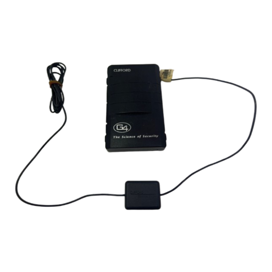
Summary of Contents for Clifford Level Four
- Page 1 Color profile: Disabled Composite Default screen The Science of Security™ Prime Level FOUR SECURITY UPGRADE PACKAGE Installation Manual D:...-922 Level 4 install manual.vp Wed Aug 04 17:37:06 1999...
- Page 2 Color profile: Disabled Composite Default screen D:...-922 Level 4 install manual.vp Wed Aug 04 17:37:06 1999...
-
Page 3: Table Of Contents
Color profile: Disabled Composite Default screen Table of Contents Wiring Diagram ........2 Important Information . -
Page 4: Wiring Diagram
Color profile: Disabled Composite Default screen Red/Green (door lock n.o.) Gray/Green (door lock n.c.) See Door Red/Orange (door unlock n.o.) Lock/Unlock Gray/Orange (door unlock n.c.) Section of Prime Level 4 Control Unit White/Green (door lock comm.) This Manual White/Orange (door unlock comm.) Siren/Car Horn Output Optional... -
Page 5: Important Information
2. Keep extension, if needed, as short as possible. Use same-gauge wire for extensions. 3. DO NOT mount components nor route wires near hot or moving vehicle parts. NOTE: Clifford Electronics’ web site for Authorized Clifford Dealers has detailed descriptions of wire colors and locations for most foreign and domestic vehicles. -
Page 6: Door Trigger/Interior Light Supply
Default screen Door Trigger/Interior Light Supply The Level FOUR has self-programming door trigger polarity. Door triggers on most vehicles are negative. To verify polarity: 1. Find the one wire off the rear of the door switch that shows +12 volts when the switch is pressed in and 0 volts when released. -
Page 7: 2-Stage
Color profile: Disabled Composite Default screen (only driver’s door unlocks 2-Stage +12V upon first press; all doors upon second RED/GREEN press) RED/ORANGE 1. Find the driver’s-door lock motor wire in the door or kick panel that Diagram 4: +12V +12V shows +12V when the doors are Reverse Polarity unlocked. -
Page 8: Optional Trunk Trigger Connection
Color profile: Disabled Composite Default screen Optional Trunk Trigger Connection The switch may be located in or near the trunk latch or at the trunk light. Otherwise you may install a pin switch in a location away from water channels. 1. -
Page 9: Optional Engine Compartment Connections
Color profile: Disabled Composite Default screen Optional Engine Compartment Connections Optional Siren Mount the siren in the engine compartment away from hot or moving parts and where it cannot be reached from under the vehicle. Point downward to avoid water collection. 1. -
Page 10: Delayed Courtesy Lights
Panic + Opt ✱ Programmable Features The Level FOUR comes preprogrammed as noted in bold text in the following tables. Using CliffNet Wizard PRO The CliffNet Wizard PRO software provides an intuitive access to all installer and end-user features through a user-friendly, graphical user interface and provides extensive diagnostic capabilities. - Page 11 Color profile: Disabled Composite Default screen User-Selectable Features (Customer Mode): 1 beep = OFF, 2 beeps= ON Feature Select Right x 1 Right x 2 Right x 3 Right x 4 Chirps*/beeps: Add a new remote Left x off**/on/quiet AutoArming: NOTE 5 —...
-
Page 12: Installer Programmable Features
Color profile: Disabled Composite Default screen Installer-Programmable Features 1. Turn on the ignition. 2. Enter the factory preset valet/programming code of “2” by toggling the valet switch (located behind the LED assembly) to the left two times, then to the right. 3. -
Page 13: System Checklist & Troubleshooting
Default screen System Checklist & Troubleshooting The following checklist will assure that you have installed the Level FOUR correctly. Each successive step requires that the previous step has been completed as indicated. NOTE: If you are still having trouble after performing the following steps, please call Clifford Technical Support Services at 1-800-444-4667. - Page 14 Color profile: Disabled Composite Default screen You either selected the wrong door lock diagram or connected the wires incorrectly. Doors unlock. Reconnect the vehicle’s power locking system to its original condition, then retest the voltages as indicated in the section and wire the locks as indicated. Door Locks You either selected the wrong door lock diagram or connected the wires Only one door locks.
- Page 15 Color profile: Disabled Composite Default screen Step 10: Test the optional Dual-Zone Piezo Sensor. Arm, wait 10 seconds, then tap the car softly with your fist. The following should occur: This is the correct response. Horn beeps five times. Hit the car firmly with your fist. The following should occur: Proceed to step 11.
- Page 16 Netherlands Headquarters Trompenburgstraat 8A 1079 TX Amsterdam 020 40 40 919 Clifford systems are covered by one or more of these Clifford Electronics USA patents: 4,158,874; 4,233,642; 4,327,444; 4,383,242; 4,430,685; 4,845,464; 4,887,064; 4,890,108; 4,922,224; 4,997,053; 5,081,667; 5,146,215; 5,157,375; 5,467,070; 5,650,744 and other patents pending AutoFax &...


Need help?
Do you have a question about the Level Four and is the answer not in the manual?
Questions and answers