Table of Contents
Advertisement
Quick Links
Download this manual
See also:
Instruction Manual
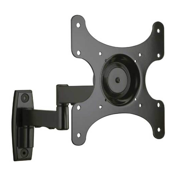
MF209/MF215 Instruction Manual
MF209
MF215
We are here to help!
Please contact Customer Service with any questions.
Customer Service
Americas: 800-359-5520 • 651-484-7988 • info@sanus.com
Europe, Middle East, and Africa: + 31 40 2324700 • europe.sanus@milestone.com
Asia Pacifi c: 86 755 8996 9226 • sanus.ap@milestone.com
·
·
SANUS
2221 Hwy 36 West
Saint Paul, MN 55113 USA
©2011 Milestone AV Technologies, a Duchossois Group Company. All rights reserved. Sanus is a division of Milestone.
All other brand names or marks are used for identifi cation purposes and are trademarks of their respective owners.
sanus.com
(6901-002129 <01>)
Advertisement
Table of Contents

Related Manuals for Sanus Visionmount MF209


Summary of Contents for Sanus Visionmount MF209
- Page 1 Saint Paul, MN 55113 USA ©2011 Milestone AV Technologies, a Duchossois Group Company. All rights reserved. Sanus is a division of Milestone. All other brand names or marks are used for identifi cation purposes and are trademarks of their respective owners.
- Page 2 Suomi - Oppaan käyttäminen English - How to use this manual For best results, reference both the text and illustrations. Cut along Saavutat parhaan tuloksen tutustumalla sekä tekstiin että kuviin. the dashed lines to match your language with the illustrations. Leikkaa katkoviivaa pitkin ja yhdistä...
- Page 3 If you do not understand these instructions, or have doubts about the safety of the installation, assembly or use of this product, contact manufacturer Customer Service or call a qualifi ed contractor. Manufacturer is not responsible for damage or injury caused by incorrect assembly or use. MF209 MF215 200 mm 200 mm (7.87 in.)
-
Page 4: Required Tools
NOTE: M4, M6, or M8 describes the diameter, mm describes the length of screws that are labeled M# x ##mm. Not all hardware included will be used. [01] x 1 MF209 [02] x 1 MF215 [02] x 1 8-32 x 0.5 in. - Page 5 M4 x 12mm M4 x 30mm [06] x 4 [07] x 4 M6 x 12mm M6 x 20mm M6 x 35mm [08] x 4 [09] x 4 [10] x 4 M8 x 12mm M8 x 35mm [11] x 4 [12] x 4 M6/M8 M6/M8 [15] x 4...
-
Page 6: Before You Begin
Before You Begin - Determine Your TV Hole Pattern 200 mm 200 mm 100 mm 100 mm 75 mm 75 mm 200 mm 75 mm 200 mm 75 mm 100 mm 100 mm Select TV Hardware and Mount TV Brackets Choose screw length and diameter Hand thread screws into the threaded inserts on the back of your TV to determine the correct screw... - Page 7 Attach selected hardware For TVs with a fl at back Ensure the bracket is level on the back of the TV. If you require additional space for cables, recesses, or protrusions, see the confi guration below. M4/M6/M8 [13], [14] [06], [08], [09], [11] [01] For TVs with an irregular back...
- Page 8 13mm 5.5mm (1/2 in.) (7/32 in.) For assitance in determining wall plate location, see Height Finder at sanus.com. Locate stud Verify the center of the stud using an awl, a thin nail, or an edge to edge stud fi nder.
- Page 9 10mm (1/2 in.) (3/8 in.) and Concrete Block For assitance in determining wall plate location, see Height Finder at sanus.com. Level wall plate [02] and mark hole locations CAUTION: Avoid potential personal injuries and property damage! Mount the wall plate [02] directly onto the concrete surface.
- Page 10 Hang TV Mount to Arm Fit nut [19] and cover [26] into underside of mount arm. NOTE: The MF209 is shown. [02] [19] [26] Place washer [18] and pivot pin [17] onto mount arm. NOTE: The MF209 is shown. [17]...
-
Page 11: Tension Adjustment
Hang TV Mount to Arm - continued Use hex key [27] to tighten mounting bolt [20] and secure mounting bracket [01] to arm [02]. [27] [20] [02] [01] Tension Adjustment A: Use hex key [27] to adjust arm extension tension. B: Adjust left/right/rotation swivel tension. -
Page 12: Wire Management
Wire Management Option A: Thread cable through channels the secure with plate [03] and plate screws [04]. Option B: Install plate [03] with plate screws [04]. Thread cable ties [05] through end holes in plate [03]. Arrange cables then secure them with the cable ties [05 NOTE: Pull the arm to its full extension before routing the cables through the channels, then loosely route the cables. - Page 13 6901-002129 <01>...
- Page 14 Suomi English Milestone AV Technologies and its affi liated corporations and subsidiaries (collectively, “Milestone”), Milestone AV Technologies sisar- ja tytäryhtiöineen (yhdessä Milestone) on pyrkinyt tekemään intend to make this manual accurate and complete. However, Milestone makes no claim that the tästä...
Need help?
Do you have a question about the Visionmount MF209 and is the answer not in the manual?
Questions and answers