Sony Power HADFX HDC-P1 Operation Manual
Hd multi purpose camera
Hide thumbs
Also See for Power HADFX HDC-P1:
- Maintenance manual (238 pages) ,
- Brochure (4 pages) ,
- Brochure (4 pages)

Related Manuals for Sony Power HADFX HDC-P1


Summary of Contents for Sony Power HADFX HDC-P1
- Page 1 HD MULTI PURPOSE CAMERA HDC-P1 OPERATION MANUAL [English] 1st Edition...
- Page 2 (controlled EMC environment, ex. TV studio). Eviter d’exposer l’appareil à un égouttement ou à des éclaboussures. Ne placer aucun objet rempli de liquide, The manufacturer of this product is Sony Corporation, 1-7-1 comme un vase, sur l’appareil. Konan, Minato-ku, Tokyo, Japan.
-
Page 3: Table Of Contents
(camera command network unit) ......7 (environnement EMC contrôlé, ex. studio de télévision). System operation example (LAN) ......7 Parts Identification ............8 Le fabricant de ce produit est Sony Corporation, 1-7-1 Konan, Front ................. 8 Minato-ku, Tokyo, Japon. Rear ................8 Le représentant autorisé... -
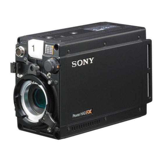
Page 4: Overview
VF detail Various functions are provided for the VF detail signal, which HDC-P1 is a 2/3-type high-definition video camera equipped can be added only on images on the monitor screen in order with CCD units for 2,200,000 pixels. The camera has a... - Page 5 Detail boost-frequency control The boost frequency can be adjusted from 20 to 30 MHz. This allows the detail thickness to be set appropriately for the subject, thus enabling more subtle image expression. H/V ratio control The ratio between horizontal and vertical detail can be adjusted.
-
Page 6: System Configuration
Caution figures. Production of some of the peripherals and related devices shown in the figures has been discontinued. For advice on choosing devices, please contact your Sony dealer or a Sony sales representative. Standalone operation example Remote Control Panel RCP-700/900-series... -
Page 7: System Operation Example (Camera Command Network Unit)
HDC1500R/1400R Camera Control Unit HDCU1000/1500 Optical fiber cable Remote Control Panel RCP-700/900-series HDC-P1 Zoom Lens (for ENG/EFP) MSU-900/950 Master Setup Unit “Memory Stick Duo” System operation example (LAN) For details on the camera settings, see “Configuring Control System Connection Settings” (page 12). -
Page 8: Parts Identification
Rear Parts Identification Front a Rear tally lamp The tally lamp lights when a call signal is generated in response to the pressing of a CALL button or a tally signal a Front tally lamp input to the EXT I/O connector. The tally lamp lights when a call signal is generated in The rear tally lamp also serves as a battery alarm function. - Page 9 e REMOTE connector (8-pin) For details on the adjustment, see “Configuring Control For connection to an RM-B150/B750 Remote Control Unit, System Connection Settings” (page 12), “MAINTENANCE RCP-700/900-series Remote Control Panel, or MSU-900/950 Menu” (page 24), “DIAGNOSIS Menu” (page 28). Master Setup Unit. l GENLOCK (external sync signal input) connector f CAMERA POWER switch and indicator (BNC type)
-
Page 10: Installation
If the screws of the tripod attachment adapter are 1/4-inch While supporting the lens, push the lens fixing lever tripod screws, use inch conversion screws (Sony Part No.: 4- A downward to secure the lens. 170-419-02) to attach the adapter. For details on purchasing inch conversion screws, and other information, contact a Sony Connect the lens cable to the LENS connector. -
Page 11: Mounting The Camera To A Tripod (When Using V Shoe And Tripod Adapter Vct-14)
Hold down the red button and pull the lever in the direction of Using V Shoe and Tripod Adapter the arrow. VCT-14) Use a separately sold V shoe (Sony Part No.: A-8279-993-C) and tripod adapter VCT-14 to mount the camera to the tripod. Notes Lever •... -
Page 12: Preparatory Settings
When the date/time setting is completed, set the Preparatory Settings DISPLAY/MENU switch to OFF to exit Menu mode. Setting the Camera Outputs Setting the Local Time You can specify video signals output from the camera, with menu operations. When the camera is used for the first time, display the Setting the output of SDI 1/2 MAINTENANCE menu on the monitor connected to the VBS connector or SDI 2 connector and set the built-in clock to the... - Page 13 Configure settings related to TCP/IP. About the menu to configure the control system connection settings For details, see “TCP/IP SETTING (MAINTENANCE menu)” (page 13). For details on menu operations, see “Menus” (page 16). Set the LAN connection. TCP/IP SETTING (MAINTENANCE menu) For details, see “LAN SETTINGS (MAINTENANCE <TCP/IP SETTING>...
-
Page 14: Adjusting The Flange Focal Length
CNS SETTINGS (MAINTENANCE menu) Place a flange focal length adjustment chart approximately 3 meters from the camera and adjust <CNS SETTINGS> M17 TOP the lighting to get an appropriate video output level. CNS MODE : LEGACY CCU NO MASTER IP ADDRESS: About 3 meters (10 ft) CNS MODE: Sets the control system connection mode. - Page 15 Rotate the menu control knob to align the pointer to You can adjust the coloring with the menu items below: “TOP” and push on the knob. PEAK COLOR: Turn the function ON/OFF to change the The TOP MENU screen is displayed. color where the detail signal is strongest.
-
Page 16: Menus
Rotate the menu control knob to align the pointer to the item to be set and push on the knob. Menus To use the level indicator Setting INDICATOR to ON displays the level indicator on the monitor. You can set the display format with the menu items below. -
Page 17: Setting The Menu
To change the displayed page Menu Purpose This menu permits you to control all items of the Check that the pointer is located at the left of the page OPERATION menu, PAINT menu, number then push on the menu control knob. MAINTENANCE menu, FILE menu, and The pointer changes to a flashing question mark. -
Page 18: Editing The User Menu
Set the cursor to the position where you wish enter a For the items on each page, see “OPERATION Menu” (page character, then push on the menu control knob. 20), “MAINTENANCE Menu” (page 24), or “DIAGNOSIS Another cursor appears on the character list. Menu”... - Page 19 Move the pointer to the item to be added (this To delete items from a page operation is unnecessary if no item exists on the page, as shown in the figure for the previous step) Move the pointer to the item to be deleted then push then push on the menu control knob.
-
Page 20: Operation Menu
The item selected in step 1 moves to the position that you Select INSERT then push on the menu control knob. selected in step 3. In the above example, <SDI OUT> moves The selection screen appears. to 04, and <VF MARKER> and the following pages move down CONTENTS one line. - Page 21 Page title Item Settings Page title Item Settings Page No. Page No. <VF MARKER> MARKER ON, OFF <FOCUS INDICATOR ON, OFF, (EFFECT) 02(U04) ASSIST> EFFECT ): Displayed WHITE, BLACK, DOT 04 (U02) when EFFECT of <VF CENTER ON, OFF MARKER> is ON. 1, 2, 3, 4 MODE BOX, B&W, COL...
-
Page 22: Paint Menu
Page title Item Settings Page title Item Settings Page No. Page No. <LENS FILE> FILE 1 to 17 <COLOR WHITE R/G/B: –99 to 99 0 08 (U07) 1 to 16: When using a TEMP> AUTO WHITE Execute by ENTER. non-serial lens BALANCE 1 to 17: When using a COLOR TEMP... - Page 23 Page title Item Settings Page title Item Settings Page No. Page No. <KNEE> K POINT R/G/B/M: –99 to 99 0 <SKIN DETAIL> SKIN DTL ON, OFF K SLOPE R/G/B/M: –99 to 99 0 SKIN GATE ON, OFF, (MAT) (MAT): Displayed when KNEE ON, OFF GATE of <MULTI...
-
Page 24: Maintenance Menu
Page title Item Settings Page title Item Settings Page No. Page No. <MULTI PHASE 0, 23, 45, 68, 90, 113, 135, <SCENE FILE> To store and read scene MATRIX> Select an axis 158, 180, 203, 225, 248, files (paint data). (angle) for which 270, 293, 315, 338 See “FILE... - Page 25 Page title Item Settings Page title Item Settings Page No. Page No. <OHB MATRIX> PHASE 0, 23, 45, 68, 90, 113, 135, <TALLY> FRONT TALLY OFF, LOW, HIGH Select an axis 158, 180, 203, 225, 248, M06 (U11) (Even if this is set to ON, (angle) for which 270, 293, 315, 338 the front tally lamp goes...
- Page 26 Page title Item Settings Page title Item Settings Page No. Page No. <DATE> DATE/TIME yyyy/mm/dd <COLOR BARS ON, OFF hh:mm BARS> HD BARS BAR 16:9 (100%), BAR <BATTERY BEFORE END 11.5 V to 17.0 V 16:9 (75%), MF-ARIB ALARM> (75%), MF-ARIB (100%), 11.0 V to 11.5 V MF-ARIB (+I), MF-SMPTE BATTERY ALARM...
-
Page 27: File Menu
Page title Item Settings Page title Item Settings Page No. Page No. <OPTION KEY> READ (MStCAM) Execute by ENTER. <SCENE FILE> To store and read scene To read the installation files (paint data): When key from a “Memory storing a file in camera Stick Duo.”... -
Page 28: Diagnosis Menu
DEFAULT x.x.x.x GATEWAY menu. See “Restoring a setting to <SERIAL NO.> MODEL HDC-P1 the default setting” (page Serial No. 18). OHB WHITE Execute by ENTER. SHADE (ALL) OHB BLACK Execute by ENTER. -
Page 29: Appendices
Avoid use or storage in the following places: Consult Sony service personnel. • Extremely hot or cold places VF RPN BUSY RPN compensation was attempted • Places with high humidity from an external device while being •... -
Page 30: Specifications
— Very humid or subject to corrosive substances • To prevent data loss, make backups of data frequently. In no event will Sony be liable for any loss of data. • Unauthorized recording may be contrary to the provisions of Label side copyright law. - Page 31 Design and specifications are subject to change without notice. Note Always verify that the unit is operating properly before use. SONY WILL NOT BE LIABLE FOR DAMAGES OF ANY KIND INCLUDING, BUT NOT LIMITED TO, COMPENSATION OR REIMBURSEMENT ON ACCOUNT OF THE LOSS OF PRESENT OR PROSPECTIVE...
-
Page 32: Menu Tree
Menu Tree OPERATION PAINT VF DISPLAY (01) LENS FILE (08) SW STATUS (P01) FILE FLARE ZOOM CENTER MARKER GAMMA DISP H POS BLK GAM FOCUS V POS KNEE STORE WHT CLIP DETAIL 5600K LVL DEP IRIS SKIN DTL WHITE MATRIX GAIN VIDEO LEVEL (P02) SHUTT... - Page 33 MAINTENANCE DETAIL 1 (P09) SHUTTER (P17) AUTO SETUP (M01) DETAIL SHUTTER AUTO BLACK LEVEL ECS FREQ AUTO WHITE LIMITER [M] NOISE SUP (P18) AUTO LEVEL LIMITER [WHT] NOISE SUP AUTO WHITE SHADING LIMITER [BLK] SCENE FILE (P19) AUTO BLACK SHADING CRISP 1/2/3/4/5 TEST...
- Page 34 FILE DIAGNOSIS GENLOCK (M12) OPERATOR FILE (F01) BOARD STATUS (D01) GENLOCK READ (MStCAM) STATUS WRITE (CAMtMS) FORMAT PRESET PHASE STORE PRESET FILE FILE ID PLD VERSION (D02) CAM CODE DATE (M13) DATE DATE/TIME SCENE FILE (F02) BATTERY ALARM (M14) 1/2/3/4/5 DPR1 BEFORE END STORE...
- Page 35 The material contained in this manual consists of information that is the property of Sony Corporation and is intended solely for use by the purchasers of the equipment described in this manual. Sony Corporation expressly prohibits the duplication of any...
- Page 36 Sony Corporation Printed in Japan HDC-P1 (SY) 2009.12 08 4-170-168-01(1) © 2009...
Need help?
Do you have a question about the Power HADFX HDC-P1 and is the answer not in the manual?
Questions and answers