Table of Contents
Advertisement
Advertisement
Table of Contents

Related Manuals for Husqvarna LZ30, LZ30C


Summary of Contents for Husqvarna LZ30, LZ30C
- Page 1 Operator Manual LZ5227 / 968999674 LZ7230 / 968999676 LZ30 / 968999776 LZ6130C / 968999752 Please read the operator’s manual carefully and make sure you understand the instructions before using the machine. LZ6130 / 968999675 LZ6127 / 968999709 LZ30C / 968999751 LZ7230C / 968999753 English...
- Page 2 ©2007 HTC. All rights reserved. Beatrice, NE. Printed in U.S.A.
-
Page 3: Table Of Contents
INTRODUCTION ... 5 General ... 5 Driving and Transport on Public Roads ... 5 Towing... 5 Operating ... 5 Good Service ... 6 Manufacturing Number ... 6 SYMBOLS AND DECALS ... 7 SAFETY ... 9 Safety Instructions ... 9 General Operation ... 9 Personal Safety Equipment ... - Page 4 WARNING! Failure to follow cautious operating practices can result in serious injury to the operator or other persons. The owner must understand these instructions, and must allow only trained persons who understand these instructions to operate the mower. Each person operating the mower must be of sound mind and body and must not be under the infl...
-
Page 5: Introduction
INTRODUCTION Congratulations Thank you for purchasing a Husqvarna ride-on mower. This machine is built for superior effi ciency to rapidly mow primarily large areas. A control panel easily accessible to the operator and a hydrostatic transmission regulated by steering controls both contribute to the machine’s performance. -
Page 6: Good Service
Good Service Husqvarna’s products are sold all over the world and only in specialized retail stores with complete service. This ensures that you as a customer receive only the best support and service. Before the product is delivered, the machine has, for example, been inspected and adjusted by your retailer. See the certifi cate in the Service Journal in this operator’s manual. -
Page 7: Symbols And Decals
These symbols are found on the machine and in the operator’s manual. Study them carefully so that you know what they mean. WARNING! Xxxx xxxxxx xxxxx xxxx xxxxxxxxx xxxxxx xxxxxxxxx. xx xxxxxxxx xxxx xxxxxx. Used in this publication to notify the reader of a risk of personal injury or death, particularly if the reader should neglect to follow instructions given in the manual. - Page 8 SYMBOLS AND DECALS Read Shut off engine and Keep a safe Use on slopes No passengers Operator’s remove key before distance from no greater Manual performing any the machine than 10° maintenance or repair work Whole body Severing of fi ngers Do not open or Careful backing up, Careful going...
-
Page 9: Safety
Safety Instructions These instructions are for your safety. Read them carefully. WARNING! This symbol means that important safety instructions need to be emphasized. It concerns your safety. IMPORTANT: THIS CUTTING MACHINE IS CAPABLE OF AMPUTATING HANDS AND FEET AND THROWING OBJECTS. - Page 10 • Operate machine only in daylight or good artifi cial light. • Do not operate the machine while under the infl uence of alcohol or drugs. • Watch for traffi c when operating near or crossing roadways. • Use extra care when loading or unloading the machine into a trailer or truck.
-
Page 11: Personal Safety Equipment
Personal Safety Equipment WARNING! When using the machine, approved personal protective equipment (shown in illustrations) shall be used. Personal protective equipment cannot eliminate the risk of injury but it will reduce the degree of injury if an accident does happen. Ask your retailer for help in choosing the right equipment. - Page 12 • Do not use on steep slopes. • Do not try to stabilize the machine by putting your foot on the ground. • Do not mow near drop-offs, ditches, or embankments. The machine could suddenly roll over if a wheel is over the edge or if the edge caves in.
-
Page 13: Safe Handling Of Gasoline
WARNING! The engine must not be started when the driver’s fl oor plate or any protective plate for the mower deck’s drive belt is removed. Safe Handling of Gasoline To avoid personal injury or property damage, use extreme care in handling gasoline. Gasoline is extremely fl... -
Page 14: General Maintenance
General Maintenance • Never operate machine in a closed area. • Keep all nuts and bolts tight to be sure the equipment is in safe working condition. • Never tamper with safety devices. Check their proper operation regularly. • Keep machine free of grass, leaves, or other debris buildup. - Page 15 • Ensure that nuts and bolts, especially the fastening bolts for the blade attachments, are properly tightened, torqued and that the equipment is in good condition. • Do not modify safety equipment. Check regularly to be sure it works properly. The machine must not be driven with defective or unmounted protective plates, protective cowlings, safety switches, or other protective...
-
Page 16: Transport
(if any). If a spark arrester is used, it should be maintained in effective working order by the operator. A spark arrester for the muffl er is available through your authorized Husqvarna dealer. 8011-515... -
Page 17: Roll Over Protection System (Rops)
• ROPS bar is NOT intended for use in sub zero temperatures. Spark Arresters A spark arrester for the muffl er is available through your authorized Husqvarna dealer. SAFETY WARNING! The rollover protection system's capabilities may be impaired by damage if... -
Page 18: Controls
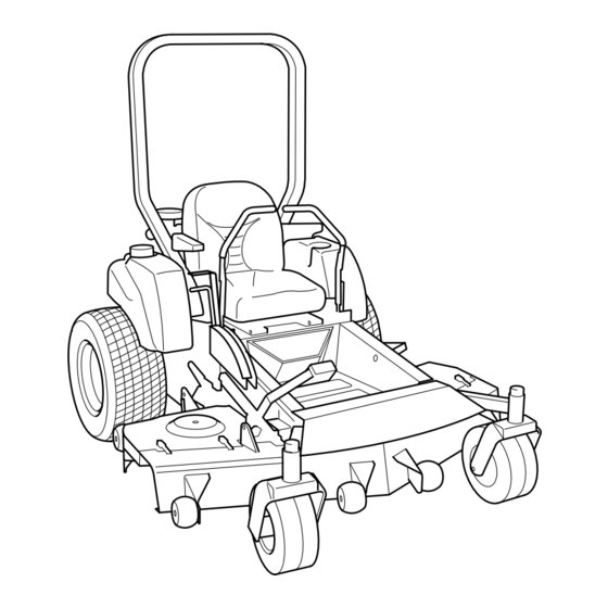
Controls This operator’s manual describes the Husqvarna Zero Turn Rider. The rider is fi tted with a Kohler four-stroke overhead valve engine developing 30 horse power*. Transmission from the engine is made via two belt- driven hydraulic pumps, which in turn drive a hydraulic motor for each drive wheel. -
Page 19: Motion Control Levers
Motion Control Levers The machine’s speed and direction are continuously variable using the two steering controls. The steering controls can be moved forward or backward about a neutral position. Furthermore, there is a neutral position, which is locked if the steering controls are moved outward. -
Page 20: Hour Meter
Hour meter The hour meter displays the total operating time. It will fl ash CHG OIL (Change Oil) at 50 hour intervals. The fl ash duration is one hour before and one hour after the interval. The CHG OIL icon will come on and shut off automatically. -
Page 21: Blade Switch
Blade switch To engage the mower deck, pull the blade switch knob out. The mower blades are disengaged when the knob is pressed down fully. Ignition Switch The ignition key is placed on the control panel and is used to start and stop the engine. WARNING! Do not run the starter for more than fi... -
Page 22: Refueling
Refueling Read the safety instructions before refueling. The machine has two fuel tanks, one on each side just behind the seat. The tank capacity is 3 gallons (11.4 liters). Regularly check the gas cap gasket for damage and keep the cap properly tightened. The engine will run on a minimum of 85-octane unleaded gasoline (no oil mix). -
Page 23: Seat Lock
Seat Lock Under the rear section of the seat is a lock device to lock the seat into a folded position. The seat has a linked fi xture at the front edge and can be folded forward when the lock is pushed. Fuel shut off valve The fuel shut off valve is located at the right rear of the seat. -
Page 24: Choke Control
Choke control The choke control is used for cold starts to provide the engine with a richer fuel mixture. For cold starts, pull the control out to its extent. Throttle control The throttle control regulates the engine speed and thereby the rate of rotation of the blades, assuming the blade switch is pulled out (see Engaging the Mower Deck). -
Page 25: Cutting Height Lift Pedal
Cutting height lift pedal On some models, there is a deck assist lift pedal to aid in maneuvering the deck lift. IMPORTANT INFORMATION In order to obtain an even cutting height it is important that the air pressure in all four tires is the same 15 psi (1 bar). -
Page 26: Operation
Operation Read the “Safety Instructions” section and the following pages if you are unfamiliar with the machine. Training Zero turn mowers are far more maneuverable than typical riding mowers due to their unique steering capabilities. We suggest that this section be reviewed in its entirety prior to attempting to move the mower under its own power. -
Page 27: Roll Bar And Safety Belt
Roll bar and safety belt Operate the unit with the roll bar in the raised and locked position and use the seat belt. There is no rollover protection when the roll bar is down. If it is necessary to lower roll bar, do not wear the seat belt. Raise the roll bar as soon as clearance permits. - Page 28 4. Disengage the mower blades by depressing the blade switch. 5. Move the steering controls outward to the locked (outer) neutral position. 6. Move the throttle to the middle position. English English OPERATION Depress the control for disengaging the mower deck Steering controls in the outward, locked neutral position Set the throttle 8011-510...
- Page 29 7. If the engine is cold, the choke control should be pushed forward to the choke position. 8. Open the valve for the selected fuel tank. 9. Press in and turn the ignition key to the start position. OPERATION Set the choke control Open the fuel valve Turn to the start position 8011-508...
- Page 30 10. When the engine starts, immediately release the ignition key back to the run position. IMPORTANT INFORMATION Do not run the starter for more than 5 seconds each time. If the engine does not start, wait about 10 seconds before retrying.
-
Page 31: Weak Battery
To start an engine with a weak battery WARNING! Lead-acid batteries generate explosive gases. Keep sparks, fl ame and smoking materials away from batteries. Always wear eye protection when around batteries. If your battery is too weak to start the engine, it should be recharged. -
Page 32: Running
Running 1. Release the parking brake by moving the lever downward. Your mower is equipped with an operator presence system. When the engine is running, any attempt by the operator to leave the seat without fi rst setting the parking brake will shut off the engine. -
Page 33: Operating On Hills
Operating on hills Read the Safety Instructions “Driving on Slopes” in the “Safety Instructions”. WARNING! Do not drive up or down hills with slopes greater than 10 degrees. Do not drive across slopes. • The slowest speed possible should be used before starting up or down hills. -
Page 34: Mowing Tips
Mowing Tips • Observe and fl ag rocks and other fi xed objects to avoid collisions. • Begin with a high cutting height and reduce it until the desired mowing result is attained. The average lawn should be cut to 2½" (64 mm) during the cool season and over 3"... -
Page 35: Stopping The Engine
Stopping the Engine Allow the engine to idle a minute in order to attain normal operating temperature before stopping it, if it has been worked hard. Avoid idling the engine for longer periods, as there is a risk of the spark plugs fouling. -
Page 36: Maintenance
Maintenance Check the parking brake Check the engine’s oil level (every refueling) Check the hydraulic system’s oil level Check the safety system Check for fuel and oil leakages Check rubber valve for sand trap Check/clean the engine’s cooling air intake Check the mower deck Check hardware (screws, nuts, etc.) Clean under the mower deck... - Page 37 Maintenance Check/adjust throttle and choke cables Check the condition of belts, belt pulleys, etc. Change the engine oil Replace the engine oil fi lter (every 200 hours) Clean/replace the spark plugs Replace the fuel fi lter Replace air fi lter (main cartridge) Check the caster wheels (every 200 hours) Clean the cooling fi...
-
Page 38: Battery
Battery Your mower is equipped with a maintenance free battery and does not need servicing. However, periodic charging of the battery with an automotive type battery charger will extend its life. • Keep battery and terminals clean. • Keep battery bolts tight. •... -
Page 39: Ignition System
Ignition System The engine is equipped with an electronic ignition system. Only the spark plug requires maintenance. For recommended spark plugs, see Technical Data. 1. Remove the ignition cable boot and clean around the spark plug. 2. Remove the spark plug with a spark plug socket wrench. - Page 40 Safety system English MAINTENANCE Start motor Works Ignition system Does not work 8011-553...
-
Page 41: Engine's Cooling Air Intake
Engine Cooling Air Intake Check that the engine’s cooling air intake is free from leaves, grass, and dirt. If the cooling air intake is clogged, engine cooling deteriorates, which can lead to engine damage. Throttle Cable Check that the engine responds to throttle increases and that a good engine speed is attained at full throttle. -
Page 42: Air Filter
Air Filter If the engine seems weak or runs unevenly, the air fi lter may be clogged. If running with a dirty air fi lter, the spark plugs can become fouled. For this reason, it is important to replace the air fi lter regularly (see the heading Maintenance Schedule for the proper service interval). -
Page 43: Engine Oil Cooler
Pull the main fi lter (outer) fi lter out. Remove the inner fi lter. Clean inside the fi lter housing, cover housing and dust cap. Wipe dry only. Reinstall or replace the inner fi lter with the open end fi rst, ensuring that it enters the housing recess. -
Page 44: Fuel Pump Air Filter
Fuel Filter Replace the line-mounted fuel fi lter every 100 hours (once per season) or more often if it becomes clogged. Move the hose clamps away from the fi lter. Use fl at-nosed pliers. Pull the fi lter loose from the hose ends. Push the new fi... -
Page 45: V-Belts
Checking the V-belts Check every 100 hours of operation. Check for severe cracking and large nicks. NOTE: The belt will show some small cracks in normal operation. The belts are not adjustable. Replace belts if they begin to slip from wear. Deck belt To replace deck belt Remove deck belt. -
Page 46: Tire Pressures
Visually check that no damage is found on the lever, links, or switch belonging to the parking brake. Perform a test drive and check that there is suffi cient braking action. To adjust the parking brake, contact the Husqvarna service workshop. WARNING! Faulty adjustment of the parking brake can cause an accident. -
Page 47: Checking The Blades
Install and tighten blade bolt securely. • Torque blade bolt to 90 ft/lbs (122 Nm). IMPORTANT INFORMATION Special blade bolt is heat treated. Replace with a Husqvarna bolt if required. Do not use a lower grade hardware than specifi ed. MAINTENANCE Check the blades 1. -
Page 48: Adjusting The Mower Deck
Adjusting the Mower Deck WARNING! Before performing any service or adjustment checklist: 1. Engage the parking brake. 2. Place the Blade switch in the disengaged position. 3. Turn ignition switch to “OFF” position and remove the key. 4. Make sure the blades and all moving parts have completely stopped. 5. -
Page 49: Cleaning And Washing
Cleaning and Washing Regular cleaning and washing, especially under the mower deck, will increase the machine’s life-span. Make it a habit to clean the machine directly after use (after it is cooled), before the dirt sticks. Do not spray water on the top of the mower deck. Use compressed air to clean the top side of mower deck. -
Page 50: Lubrication
Lubrication Schedule Lubrication schedule and Symbol Key 12/12= Every year 1/52= Every Week 1/365= Every day General Remove the ignition key to prevent unintentional movements during lubrication. When lubricating with an oil can, it must be fi lled with engine oil. When lubricating with grease, unless otherwise stated, use a high grade molybdenum disulphide grease. -
Page 51: Lubricating Cables
Lubricating the Cables If possible, grease both ends of the cables and move the controls to end stop positions when lubricating. Refi t the rubber covers on the cables after lubrication. Cables with sheaths will bind if they are not lubricated regularly. If a cable binds, it can disrupt operation. -
Page 52: Engine Oil
Engine Oil Changing the Engine Oil Change oil after every 100 hours of operation (more frequently under severe conditions). Refi ll with service class SG, SH, SJ or higher oil as specifi ed in the Viscosity Grades table. Change the oil while the engine is still warm. The oil will fl... -
Page 53: Oil Level
Checking the Oil Level The importance of checking and maintaining the proper oil level in the crankcase cannot be overemphasized. Check oil before each use as follows: 1. Make sure the engine is stopped, level, and cool so the oil has had time to drain into the oil pan. -
Page 54: Oil Recommendations
Oil Recommendations Using the proper type and weight of oil in the crankcase is extremely important. So is checking oil daily and changing oil regularly. Failure to use the correct oil, or using dirty oil, causes premature engine wear and failure. Oil Type Use high quality detergent oil of API (American Petroleum Institute) service class SG, SH, SJ... -
Page 55: Throttle And Choke Cables, Lever Bearings
Throttle and Choke Cables, Lever Bearings Lubricate the cable ends by the carburetor with the oil can. Move the controls to the end points and lubricate again. The throttle cable is also lubricated by the control when the control console is removed. On Kohler engine the cables are placed under the air fi... -
Page 56: Steering Control Shafts
Steering Control Shafts Tip the driver’s seat. Lubricate with a grease gun, one zerk for each steering control shaft, until the grease is forced out. Use only good quality molybdenum disulphide grease. Grease from well-known brand names (petrochemical companies, etc.) usually maintains a good quality. Mower Deck Struts Lubricate with a grease gun, one zerk for each strut, until the grease is forced out. -
Page 57: Troubleshooting Guide
TROUBLESHOOTING GUIDE Problem The engine will not start. The starter does not turn the engine over. The engine runs rough. Cause • The blade switch is engaged. • The steering controls are not locked in the neutral position. • The driver is not sitting in the driver’s seat. •... - Page 58 TROUBLESHOOTING GUIDE Problem The engine seems weak. The engine overheats. Battery not charging. The machine moves slowly, unevenly, or not at all. Mower deck not engaging. Transaxle leaks oil. Uneven mowing results. The machine vibrates. English Cause • Clogged air fi lter. •...
-
Page 59: Storage
Service When ordering spare parts, please specify the purchase year, model, type, and serial number. Always use genuine Husqvarna spare parts. An annual check-up at an authorized service workshop is a good way to ensure that your machine performs its best the following season. -
Page 60: Wiring Diagrams
For unit produced before Serial No. 074439861 SOLENOID RIGHT MOTION CONTROL LEVER LEFT MOTION CONTROL LEVER SEAT ELECTRIC CLUTCH For Serial No. 074439861 and after START RELAY SOLENOID LT. BLU LEFT MOTION CONTROL LEVER BRAKE SWITCH RIGHT MOTION CONTROL LEVER ORG/WHT ELECTRIC CLUTCH... -
Page 61: Technical Data
Engine Manufacturer Type Power Lubrication Oil capacity excluding fi lter Oil capacity including fi lter Engine oil (See viscosity diagram) Fuel Fuel tank capacity Spark plugs / gap Cooling Air fi lter Alternator Starter Transmission Transmission Speed and direction controls Speed forward Speed reverse Brakes... - Page 62 Cutting Width Cutting Height Uncut Circle Number of Blades Blade Length Nose Rollers Sprung Seat Hinged Arm Rests Hour Meter Blade Engagement Deck Construction Productivity Productivity Overall Dimensions Weight Base Machine Length Base Machine Width Base Machine Height Overall Width, Chute Up Overall Width, Chute Down English English...
- Page 63 Engine Manufacturer Type Power Lubrication Oil capacity excluding fi lter Oil capacity including fi lter Engine oil (See viscosity diagram) Fuel Fuel tank capacity Spark plugs / gap Cooling Air fi lter Alternator Starter Transmission Transmission Speed and direction controls Speed forward Speed reverse Brakes...
- Page 64 Cutting Width Cutting Height Uncut Circle Number of Blades Blade Length Nose Rollers Sprung Seat Hinged Arm Rests Hour Meter Blade Engagement Deck Construction Productivity Productivity Overall Dimensions Weight Base Machine Length Base Machine Width Base Machine Height Overall Width, Chute Up Overall Width, Chute Down English English...
- Page 65 Engine Manufacturer Type Power Lubrication Oil capacity excluding fi lter Oil capacity including fi lter Engine oil (See viscosity diagram) Fuel Fuel tank capacity Spark plugs / gap Cooling Air fi lter Alternator Starter Transmission Transmission Speed and direction controls Speed forward Speed reverse Brakes...
-
Page 66: Accessories
Accessories Head lights BioClip attachment (Mulch clip) Collection system Torque Specifi cations • Engine crankshaft bolt 50 ft/lb (67 Nm) • Deck pulley bolts 45 ft/lb (61 Nm) • Lug nuts 75 ft/lb (100 Nm) • Blade bolt 27-35 ft/lb (35-45 Nm) •... -
Page 67: Conformity Certificates
CONFORMITY CERTIFICATES Conformity Certifi cates USA requirements Labels are placed on the engine and/or in the engine compartment stating that the machine will fulfi ll the requirements. This is also applicable to special requirements for any of the states, (California emission rules etc.). Do not remove any of these labels. -
Page 68: Service Journal
Service Journal Action Delivery Service 1. Charge the battery. 2. Adjust the tire pressure of all wheels to 15 PSI (1 bar). 3. Mount the steering controls in the normal position. 4. Connect the contact box to the cable for the seat’s safety switch. - Page 69 SERVICE JOURNAL After the First 5-8 Hours 1. Change engine oil. English...
-
Page 70: Hour Service
SERVICE JOURNAL Action Date, mtr reading, stamp, sign 25-Hour Service 1. Check the fuel pump’s air fi lter. 2. Sharpen/Replace mower blades if required. 3. Check the tire pressures. 4. Check battery with cables. 5. Lubricate according to lubrication chart. 6. - Page 71 SERVICE JOURNAL Action Date, mtr reading, stamp, sign 50-Hour Service 1. Perform the 25-hour service. 2. Clean/replace the air cleaner’s fi lter cartridge (paper fi lter) (shorter intervals for dusty operating conditions). Change engine oil. 4. Lubricate according to lubrication chart. 5.
-
Page 72: 100-Hour Service
Action 100-Hour Service 1. Perform the 25-hour service. 2. Perform the 50-hour service. 3. Change the engine oil fi lter. 4. Clean/replace the spark plugs. 5. Replace the fuel fi lter. 6. Clean the cooling fi ns on the engine and transmission. Check V-belts. -
Page 73: 300-Hour Service
SERVICE JOURNAL Action Date, mtr reading, stamp, sign 300-Hour Service 1. Inspect the machine. Come to agreement with the customer as to which additional work is to be carried out. 2. Perform the 25-hour service. 3. Perform the 50-hour service. 4. -
Page 74: At Least Once Each Year
SERVICE JOURNAL Action Date, mtr reading, stamp, sign At Least Once Each Year 1. Clean the engine’s cooling air intake (25 hours). 2. Replace the air cleaner’s pre-fi lter (foam) (300 hours). 3. Replace the air fi lter’s paper cartridge. 4. - Page 75 SERVICE JOURNAL Action Date, mtr reading, stamp, sign English...
-
Page 76: Warranty Statement
It is the Owner’s and Retailer’s responsibility to make certain that the Warranty Registration Card is properly filled out and mailed to Husqvarna Forest & Garden Company. This card should be mailed within ten (10) days from the date of purchase in order to confirm the warranty and to facilitate post-sale service. - Page 77 539 131254 R01 08/23/07...
Need help?
Do you have a question about the LZ30, LZ30C and is the answer not in the manual?
Questions and answers