Table of Contents
Advertisement
Quick Links
Advertisement
Table of Contents

Related Manuals for Go Power GP-SWR-A


Summary of Contents for Go Power GP-SWR-A
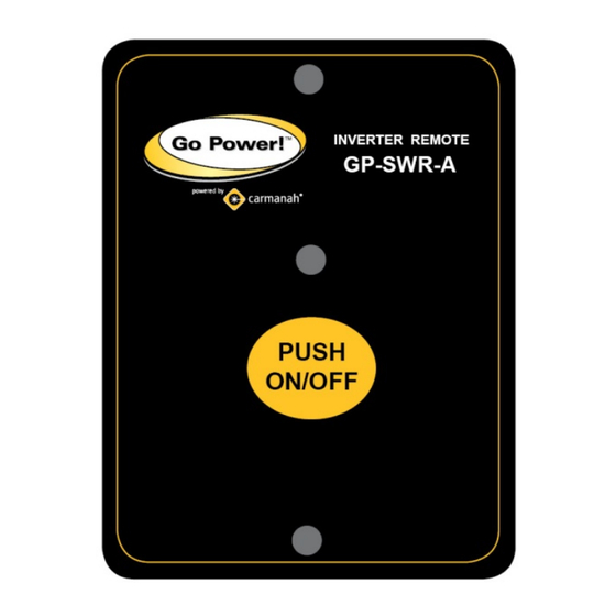
- Page 1 GP-SWR-A Remote ________________________________________________ Owner’s Manual ...
-
Page 2: Specifications
Ignition Lockout is activated Reverse Over-Ride Function (ROF) is activated 2.0 Specifications GP-SWR-A REMOTE SPECIFICATIONS 10.5-60VDC (Based on the battery input voltage of the inverter—it can be used Input Voltage Range for 12V, 24V and 48V inverters) Operating Temperature Range 0-40°C... - Page 3 GP‐SWR‐A ___________________________________________________________ 3.1 Reverse Override Function (ROF) In some RV’s, a TV monitor is used in conjunction with a camera which allows the driver to view the area behind the vehicle while reversing. If the TV monitor is in view of the driver, it should remain off, and should only be turned on when the vehicle is reversing.
- Page 4 GP‐SWR‐A ___________________________________________________________ The wire feeding the “+” battery voltage signal to the ¼” connector for the ROF or Ignition Lockout functions should have a 0.5A fuse in series for protection. 3.3 Selecting ROF or Ignition Lockout Functions Jumper JP1 is placed inside the remote control and is used to select either Reverse Override Function or Ignition Lockout Function (open the back cover for access to the jumper JP-1).
- Page 5 GP‐SWR‐A ___________________________________________________________ 4.0 Installation 1. Refer to the drawing for hole and cutout dimensions. 2. Use the cable between CR8 remote and the inverter. 3. Switch the inverter to REMO position. 4.1 GP-SWR-A Remote Control Cables ...
- Page 6 5.0 Mounting the Remote Step 1- Cut out the template (on page 8) attached and position it on the wall where the remote is to be mounted. Step 2- Mark the location of the two holes, and the square area to be cut out. Note: Remote switch assembly requires 0.7”...
- Page 7 GP‐SWR‐A ___________________________________________________________ 5.1 Mounting Template CARMANAH BATTERY CAR BATTERIES...
Need help?
Do you have a question about the GP-SWR-A and is the answer not in the manual?
Questions and answers