Table of Contents
Advertisement
Quick Links
PURE SINE WAVE INVERTER REMOTE
GP-ISW-R-12/24
User Manual
GP-ISW-R
© 2018 Go Power!
Worldwide Technical Support and Product Information
Go Power! Corporate Headquarters
201-710 Redbrick St. Victoria, BC Canada V8T 5J3
Tel: 1.866.247.6527
80325_MANUAL_ISW-R_RevB
15
14
13
12
11
10
a wholly-owned subsidiary of Valterra Products, LLC.
®
®
gpelectric.com
GP-ISW-R
gpelectric.com
Advertisement
Table of Contents

Related Manuals for Go Power GP-ISW-R-12


Summary of Contents for Go Power GP-ISW-R-12
-
Page 1: User Manual
PURE SINE WAVE INVERTER REMOTE GP-ISW-R-12/24 User Manual GP-ISW-R ® gpelectric.com GP-ISW-R © 2018 Go Power! a wholly-owned subsidiary of Valterra Products, LLC. ® Worldwide Technical Support and Product Information gpelectric.com Go Power! Corporate Headquarters 201-710 Redbrick St. Victoria, BC Canada V8T 5J3 Tel: 1.866.247.6527... - Page 2 Error condition indicator (High Battery, Low Battery, Over Temperature, Over Load conditions) • Action condition indicator (INV, POWER SAVING, GRID) SPECIFICATIONS Specification Item GP-ISW-R-12/24 Input Voltage 10.5 ~ 66VDC Operating Temperature Range 0 ~ 40°C Storage Temperature Range -30°C ~ 70°C Standby Current Draw <...
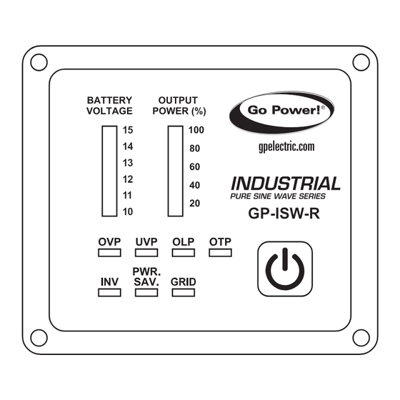
- Page 3 4. INTRODUCTION FRONT PANEL INTRODUCTION ® gpelectric.com GP-ISW-R-12 Note: the 24 volt inverter remote’s Battery voltage indicator reads “20, 22, 24, 26, 28, 30.” Power ON/OFF button Battery voltage indicator Output power indicator Other indicators POWER ON/OFF BUTTON Power ON/OFF button turns the inverter on or off.
- Page 4 4. INTRODUCTION BATTERY VOLTAGE INDICATOR Battery voltage indicator will move up and down as the battery voltage changes. Ideally, the voltage should remain in the green area of the bar chart. If the voltage goes into the red area at the top and bottom of the bar chart, the inverter may shut down.
- Page 5 4. INTRODUCTION REAR PANEL INTRODUCTION Connector 10.5 Ø4.5 Ø4.5±0.3 AUX port Phone jack connector AUX PORT Note: the AUX port is only used in work trucks. The connector (shown above) attached to AUX wire (AWG 14 or 16) must be con- nected with a 12V / 0.5A fuse.
- Page 6 4. INTRODUCTION PHONE JACK CONNECTOR Before connecting, make sure to switch the inverter to REMOTE mode. Connect the RJ-11 cable between the ISW-R remote and the inverter. WIRE COLOR BLUE 14.6±0.3 YELLOW 12.4±0.3 GREEN BLACK 12.4±0.3 14.6±0.3 WHITE WARNING! DO NOT use a standard telephone cable. page 6 | gpelectric.com...
- Page 7 4. INTRODUCTION The JP1 is to set either the Return Override function or the Ignition Lockout function. • JP1 jumper “Short” - Return Override function: Turns ON the inverter when the auxiliary input wiring is connected to the reversed gear shift with 12 volts. •...
- Page 8 © 2018 Go Power! a wholly-owned subsidiary of Valterra Products, LLC. ® Worldwide Technical Support and Product Information gpelectric.com Go Power! Corporate Headquarters 201-710 Redbrick St. Victoria, BC Canada V8T 5J3 Tel: 1.866.247.6527 80325_MANUAL_ISW-R_RevB...
Need help?
Do you have a question about the GP-ISW-R-12 and is the answer not in the manual?
Questions and answers