Table of Contents
Advertisement
Quick Links
REMOTE CONTROL
GP-ICR-50
User Manual
GP-ICR-50
INVERTER
ON/OFF
CHARGER
ON/OFF
© 2022 Go Power!
Worldwide Technical Support and Product Information
Go Power! | Dometic
201-710 Redbrick Street Victoria, BC, V8T 5J3
Tel: 1.866.247.6527
79498_MAN_GP_ICR_50_Rev_C
ENTER / SET
gpelectric.com
®
SHORE POWER
UNIT READINGS
UNIT SETUP
REMOTE SETTINGS
BACK
Advertisement
Table of Contents

Related Manuals for Go Power DOMETIC GP-ICR-50


Summary of Contents for Go Power DOMETIC GP-ICR-50
- Page 1 SHORE POWER ON/OFF UNIT READINGS UNIT SETUP CHARGER REMOTE SETTINGS ON/OFF ENTER / SET BACK © 2022 Go Power! Worldwide Technical Support and Product Information gpelectric.com Go Power! | Dometic 201-710 Redbrick Street Victoria, BC, V8T 5J3 Tel: 1.866.247.6527 79498_MAN_GP_ICR_50_Rev_C...
- Page 2 Congratulations on purchasing your Go Power! GP-ICR-50. The remote control enables you to monitor and customize your Go Power! Inverter / Charger. This manual will aid in the process of installing and operating the Go Power! Remote Control. Please read and understand this manual before installing the Go Power! Remote Control. Please retain this manual for future reference.
-
Page 3: Table Of Contents
CONTENTS 2. GENERAL INFORMATION ............................. 4 2.1 CAUTIONS ......................4 2.2 DISCLAIMERS ......................7 2.3 GP-ICR-50 KIT PARTS .....................7 2.3.1 PARTS CHECKLIST ..................7 2.4 REMOTE FEATURES ....................8 3. INSTALLATION .........................10 3.1 TYPICAL SYSTEM OVERVIEW ................10 3.2 UNIT DIMENSIONS ..................... 14 3.3 MOUNTING REQUIREMENTS................14 3.4 INSTALLATION TOOLS .................. -
Page 4: General Information
2.1 CAUTIONS / WARNINGS This document contains important safety instructions for the products Go Power! produces. Read all instructions and cautionary markings on the product and on any accessories or additional equipment included in the installation. Failure to follow these instructions could result in severe shock or possible electrocution. - Page 5 GENERAL INFORMATION PERSONAL SAFETY Use safe lifting techniques when lifting this equipment as recommended by the Occupational Safety and Health Association (OSHA) or other local codes. Use standard safety equipment when working on this equipment, such as safety glasses, ear protection, steel-toed safety boots, safety hard hats, etc. Use standard safety practices when working with electrical equipment.
- Page 6 Make sure all devices are de-energized or disconnected to avoid causing a spark. Use the battery types recommended by Go Power!. Follow the battery manufacturer’s recommendations for installation and maintenance. Insulate batteries as appropriate against freezing temperatures. A discharged battery will freeze more easily than a charged one.
-
Page 7: Disclaimers
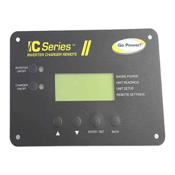
RV technician or professional electrician to ensure adherence to relevant electrical codes. We have made every reasonable effort to ensure the accuracy of the instructions in this manual, but Go Power! does not guarantee that the information is error free, nor do we make any other representation, warranty or guarantee that the information is accurate, correct, reliable or current. - Page 8 GENERAL INFORMATION Charger Status Unit Status LCD Display Mounting Holes ® Shore Power Menu IC Series Unit Readings Inverter ON/OFF INVERTER Menu SHORE POWER Switch ON/OFF UNIT READINGS UNIT SETUP IC Series CHARGER REMOTE SETTINGS ON/OFF Unit Setup Menu GP-ICR-50 Setup Menu Charger ON/OFF Switch...
- Page 9 GENERAL INFORMATION RJ 11 Cable Entry Point 2” (31mm) Mounting Holes - These 4 holes are used to attach the GP-ICR-50 to a suitable wall, using the 4 x Phillips screws included. LCD Display - The 4 line LCD display shows the status and information for the Inverter/Charger. All setup menus and current status figures appear on the LCD Display.
-
Page 10: Installation
Inverter/Charger diagrams show where the remote and Inverter / Charger are installed and how the mobile power system can be integrated with a Go Power! RV Solar Kit (sold separately by Go Power, please contact us direct.) Solar Panels Refrigerator... - Page 11 INSTALLATION GP-IC-Remote Solar Controller Cable to Battery Bank Cable to IC Series AC Power OUTPUT - to RV appliances AC Power INPUT - from Shore Power/Generator (Fuses/Breakers not shown) IC Series IC Series Inverter/Charger Inverter/Charger Cables to/from Battery Bank Cables From Battery Bank Solar Charge Controller gpelectric.com | [page 11]...
- Page 12 AC Transfer Switch Refrigerator Vent Cover Cable Entry Plate Main Pane Solar Charge Controller Earth Ground (RV, Boat Ground) Fuse Battery Temperature Sensor To Battery Bank To Battery Bank Typical RV Solar Kit (sold separately by Go Power) [page 12] | gpelectric.com...
- Page 13 INSTALLATION Generator Power 120/240 VAC Remote Control (Optional) 120 VAC 240 VAC (cabin install) 120 VAC Sub Panel IC Series Inverter/Charger DC Panel Battery Disconnect Switch (not required if circuit breaker is used) Fuse or Circuit Breaker Battery Bank gpelectric.com | [page 13]...
-
Page 14: Unit Dimensions
INSTALLATION 3.2 UNIT DIMENSIONS 4.7” (120mm) 1.22” (31mm) 5.9” (149mm) 5.2” (133mm) ® INVERTER SHORE POWER ON/OFF UNIT READINGS UNIT SETUP CHARGER REMOTE SETTINGS ON/OFF ENTER / SET BACK 3.3 MOUNTING REQUIREMENTS The GP-ICR-50 control must be installed in a location that is clean dry and protected. Make sure the LCD screen is visible and access to the menu navigation buttons is clear and un-obstructed. -
Page 15: Mounting Procedure
INSTALLATION 3.5 MOUNTING PROCEDURE To mount the GP-ICR-50 in a wall, the opening behind the wall must be at least 2” (5cm) of depth to allow room for the remote and cable. 1. Cut a 3” x 5” rectangular opening in the wall, ensure there is enough material for the screws to securely mount the remote. 2. -
Page 16: Operation
4. OPERATION 4.1 REMOTE NAVIGATION “DEFAULT HOME SCREEN” ® ® INVERTER INVERTER Go Power ! DC Status SHORE POWER SHORE POWER ON/OFF ON/OFF Initializing… 11.68 V UNIT READINGS UNIT READINGS 0.0 A UNIT SETUP UNIT SETUP CHARGER REMOTE SETTINGS CHARGER... - Page 17 OPERATION ® ® INVERTER DC Status INVERTER AC INPUT SHORE POWER SHORE POWER ON/OFF ON/OFF 11.68 V UNIT READINGS UNIT READINGS 0.0 A UNIT SETUP UNIT SETUP 0 Hz CHARGER REMOTE SETTINGS CHARGER REMOTE SETTINGS ON/OFF ON/OFF “SUB MENU “SUB MENU DOWN”...
-
Page 18: Sub Menu Items/Options
OPERATION 4.2 SUB MENU ITEMS/OPTIONS Menu Heading Selections / Adjustments Range Default Setting Shore Pow Max 5 - 50A 11.68V 0.0A AC INPUT 0 Hz Read Only VAC OUT 120 V 60.0 Hz Temperature Batt : 20.0°C Trans : 30.5°C Fets : 30.6°C 01 Search Watts OFF, 5 - 50W... -
Page 19: Shore Power Max Menu
OPERATION 4.3 SHORE POWER MAX MENU Menu Heading Selections / Adjustments Range Default Setting Shore Power Max 5 - 50A The shore power max menu enables the user to quickly change your shore max setting to coordinate with the circuit breaker rating from the incoming AC source. - Page 20 OPERATION Menu Heading Selections / Adjustments Range Default Setting 11.68V 0.0A AC INPUT 0 Hz Read Only VAC OUT 120 V 60.0 Hz Temperature Batt: 20.0°C Trans: 30.5°C Fets: 30.6°C 1. DC STATUS The first value: 11.68 V displays the voltage (VDC) from the battery bank connected to the .
-
Page 21: Unit Setup Menu
OPERATION 4. TEMPERATURE Batt: Displays the temperature of the battery temp sensor Inverter/Charger ® which should be connected to the battery bank Trans: Displays the temperature of the main power transformer inside the INVERTER Temperature SHORE POWER ON/OFF Batt : 20.0°C Inverter/Charger UNIT READINGS Trans : 30.5°C... - Page 22 OPERATION 1. SEARCH WATTS The search watts feature helps save the battery power by reducing the Inverter/ ® output to search pulses when there is no detectable load. Charger If a load greater than the wattage level setting turns on while the Inverter INVERTER UNIT SETUP SHORE POWER...
- Page 23 OPERATION 4. MAX CHARGE TIME The max charge time is a safety feature that ensures abnormal conditions ® do not cause the charger to hold batteries at a high voltage for a prolonged period of time. INVERTER UNIT SETUP SHORE POWER ON/OFF This option sets the maximum time the charger is allowed to charge the 04 Max .
- Page 24 OPERATION Setting the charge rate to 0% will stop the batteries from charging whilst continuing to allow pass through power. Setting the charge rate between ® 0 - 100% will limit/increase the charge rate to the battery bank. Reducing the charging rate can help to reduce battery overheating caused by charging at high charge rate %.
- Page 25 OPERATION 8. EQUALIZATION The equalize setting is used to remove sulfates that may have built up on ® the plates within the battery. The build up of sulfates on the battery plates can reduce the overall capacity of the battery. INVERTER UNIT SETUP SHORE POWER...
-
Page 26: Remote Settings Menu
OPERATION 4.6 REMOTE SETTINGS MENU The remote settings menu provides access to a range of settings that are based around the remote control operation including system information and the opportunity to re-load factory default values. Remote : 1544.1 Model & Revisions Read Only Inverter : 1537.1 Load Defaults... - Page 27 OPERATION 4. POWER SAVE The power save setting is used to control the LCD back light of the remote ® control screen. Shutting down the back light will save DC power and elim- inate glare from the screen. Whenever the remote goes into power save mode, the back light can be reactivated by pressing any button.
- Page 28 OPERATION Beeping Counts for Error Modes Beep Counts Description UTP (Under Temp Protection) OTP (Over Temp Protection) OVP (Over Voltage Protection) UVP (Under Voltage Proection) Short-circuit or OLP (Over Load Protection) [page 28] | gpelectric.com...
-
Page 29: Warranty Return Procedure
2. Return defective product to place of purchase Unless approved by Go Power! Management, all product shipped collect to Go Power! will be refused. Test items or items that are not under warranty, or units that are not defective, will be charged a minimum bench charge of ($50.00 US) plus taxes and shipping. A 15% restocking charge will be applied on goods returned and accepted as “new”... -
Page 30: End Of Life - Recycling Information
If you have no local certified e-waste recycling centre, the GP-ICR-50 can be dis-assembled manually and recycled responsibly. A Phillips screwdriver is required to disassemble the GP-ICR-50. Note: The GP-ICR-50 should only be dis-assembled at the end of its service life, Go Power! provides no spare parts for the GP-ICR-50. Metal Recycling... -
Page 32: Appendix
APPENDIX [page 32] | gpelectric.com... - Page 33 APPENDIX gpelectric.com | [page 33]...
- Page 34 © 2022 Go Power! Worldwide Technical Support and Product Information gpelectric.com Go Power! 201-710 Redbrick Street Victoria, BC, V8T 5J3 Tel: 1.866.247.6527 79498_MAN_GP_ICR_50_Rev_C...
Need help?
Do you have a question about the DOMETIC GP-ICR-50 and is the answer not in the manual?
Questions and answers
Red light showing on the Inverter on/off button. Green light on charger button. Screen shows bulk charge but Unit doesn’t seem to be charging. No **** noise.