Table of Contents
Advertisement
TIARA I-B
TIARA II-B
DIRECT VENT ROOM HEATER
Models:
TIARAI-BK-B
TIARAI-BR-B
TIARAI-CTO
TIARAI-CES
• Important operating and
maintenance instructions
included.
WARNING: If the information in these
instructions is not followed exactly, a fi re
or explosion may result causing property
damage, personal injury, or death.
• Do not store or use gasoline or other fl am-
mable vapors and liquids in the vicinity of this
or any other appliance.
• What to do if you smell gas
- Do not try to light any appliance.
Do not touch any electrical switch. Do not
use any phone in your building.
- Immediately call your gas supplier from a
neighbor's phone. Follow the gas supplier's
instructions.
- If you cannot reach your gas supplier, call
the fi re department.
• Installation and service must be performed
by a qualifi ed installer, service agency, or the
gas supplier.
Installation and service of this appliance should be
performed by qualifi ed personnel. Hearth & Home
Technologies suggests NFI certifi ed or factory-trained
professionals, or technicians supervised by an NFI
certifi ed professional.
TIARAII-BK-B
TIARAII-BR-B
TIARAII-CTO
TIARAII-CES
DO NOT DISCARD THIS MANUAL
• Read, understand and
follow these instructions
for safe installation and
operation.
CAUTION
• Leave this manual with
party responsible for use
and operation.
• Alert children and adults to hazards of high temperatures.
• Do NOT operate with protective barriers open or removed.
• Keep clothing, furniture, draperies and other combustibles
away.
In the Commonwealth of Massachusetts:
• installation must be performed by a licensed plumber or gas
fi tter.
See Table of Contents for additional Commonwealth of Mas-
sachusetts requirements.
This appliance may be installed as an OEM installation in manufactured
home (USA only) or mobile home and must be installed in accordance with
the manufacturer's instructions and the manufactured home construction
and safety standard, Title 24 CFR, Part 3280 or Standard for Installation
in Mobile Homes, CAN/CSA Z240MH.
This appliance is only for use with the type(s) of gas indicated on the
rating plate.
7010-149L
Owner's Manual
Installation and Operation
Tested and
Listed by
OMNI-Test Laboratories, Inc.
WARNING
HOT! DO NOT TOUCH.
SEVERE BURNS MAY RESULT.
CLOTHING IGNITION MAY RESULT.
Glass and other surfaces are hot during oper-
ation and cool down.
• Keep children away.
• CAREFULLY SUPERVISE children in same
room as appliance.
O-T L
O-T
Beaverton
Oregon USA
C
US
November 14, 2007
Advertisement
Table of Contents

Subscribe to Our Youtube Channel
Related Manuals for Heat & Glo TIARAI-BK-B


Summary of Contents for Heat & Glo TIARAI-BK-B
-
Page 1: Installation And Operation
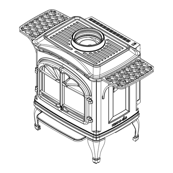
Owner’s Manual Installation and Operation TIARA I-B TIARA II-B DIRECT VENT ROOM HEATER Models: TIARAI-BK-B TIARAII-BK-B O-T L Beaverton Tested and Oregon USA Listed by TIARAI-BR-B TIARAII-BR-B OMNI-Test Laboratories, Inc. TIARAI-CTO TIARAII-CTO TIARAI-CES TIARAII-CES CAUTION DO NOT DISCARD THIS MANUAL •... - Page 2 Read this manual before installing or operating this appliance. Please retain this owner's manual for future reference. Congratulations This Owner's Manual should be retained for future reference. Congratulations on selecting a Heat & Glo gas appliance - We suggest that you keep it with your other important an elegant and clean alternative to wood burning appliances.
-
Page 3: Table Of Contents
- TABLE OF CONTENTS - Section 8: Appliance Setup Section 1: Listing and Code Approvals A. Remove Shipping Materials ....30 A. Appliance Certifi cations ......4 B. Top to Rear Conversion ......30 B. Glass Specifi cations ......4 C. Damper Adjustment ......31 C. -
Page 4: Section 1: Listing And Code Approvals
Listing and Code Approvals C. Specifi cations A. Appliance Certifi cation Model Maximum Minimum Orifi ce *Steady **P.4 Input Input Size State (US or Canada) Effi ciency MODEL Tiara I B LABORATORY OMNI-Test Laboratories, Inc. Tiara I B 31,000 22,000 .106 81.43 57.33... -
Page 5: Requirements For The Commonwealth Of Massachusetts
Inspection NOTE: The following requirements reference various The state or local gas inspector of the side wall horizontally Massachusetts and national codes not contained in this vented gas fueled equipment shall not approve the installa- document. tion unless, upon inspection, the inspector observes carbon monoxide detectors and signage installed in accordance with G. -
Page 6: Section 2: Getting Started
Getting Started C. Inspect Appliance & Components A. Design & Installation Considerations Heat & Glo direct vent gas appliances are designed to oper- ate with all combustion air siphoned from outside of the WARNING building and all exhaust gases expelled to the outside. No additional air source is required. -
Page 7: Section 3: Appliance Location & Clearances A. Selecting Appliance Location
Appliance Location and Clearances NOTE: WARNING · Illustrations refl ect typical installations and are FOR Fire Risk DESIGN PURPOSES ONLY. Provide adequate clearance: · Illustrations/diagrams are not drawn to scale. • Around air openings · Actual installation may vary due to individual design •... -
Page 8: Clearances To Combustibles - Tiara Ii-B
C. Clearances to Combustibles - Tiara II-B "A" measurement is from appliance top, not side 90˚ o ff top up and out ceiling Top of Side of Inside Model pipe pipe Outside corner wall vent Tiara II B Inches 5-1/4 31-3/4 1-1/2 Millimeters... -
Page 9: Vent Termination Minimum Clearances
Termination Locations A. Vent Termination Minimum Clearances HORIZONTAL WARNING OVERHANG Fire Risk. 2 FT. 2 FT. Explosion Risk. MIN. VERTICAL WALL Maintain vent clearance to combustibles LOWEST DISCHARGE as specifi ed. OPENING • Do not pack air space with insulation or TERMINATION other materials. - Page 10 (See Note 2) U.S. (3 FT) Electrical Service J or K = VENT TERMINAL = AIR SUPP L Y INLET = ARE A WHERE TERMINA L IS NOT PERMITTED = 3 ft. (U.S.A. ) = 12 inche s ..... clearances above grade , veran- 6 f t.
-
Page 11: Section 5: Vent Information
Vent Information A. Venting Components B. Use of Elbows In order to comply with applicable codes and product warranties, use only following venting components: CAUTION • Hearth & Home Technologies (HHT) ALL vent confi guration specifi cations MUST be followed. •... -
Page 12: How To Use The Vent Graph
How to Use the Vent Graph Venting Guidelines NOTE: IF YOUR INSTALLATION FALLS WITHIN A SHADED AREA ON • The maximum horizontal vent run is 20 ft. (6m) when the THE GRAPH, THE DAMPER MUST BE USED.* SEE INFORMATION ON vertical vent rise is 10 ft. -
Page 13: Horizontal Termination
F. Horizontal Termination WARNING Fire Hazard. Type A - Up & Out Installation Exhaust Fume Risk. Impaired Performance of Appliance. 90° ELBOW • Ensure vent components are locked together correctly. CENTER LINE • Pipe may separate if not properly joined. SLK-01TRD (recommended f PIPE LENGTH optimum performance) - Page 14 Step 3. For installations using a round support box/wall thimble Wood (check pipe manufacturer's instructions), mark the wall for a Screw 10 in. x 10 in. (254mm x 254mm) square hole. The center of the square hole should line up with the center line of the horizontal pipe, as shown in Figure 5.5.
- Page 15 Vinyl Siding WARNING Apply Sealant to all Four Sides Fire Hazard. Screws Exhaust Fume Risk. Impaired Performance of Appliance. • Ensure vent components are locked together correctly. Bold Horizontal Top to Vinyl Standoff • Pipe may separate if not properly joined. Screws Wall Thimble Cover Vinyl Siding Standoff with...
-
Page 16: Vertical Termination
G. Vertical Termination 1. Direct Vent Pipe VERTICAL TERMINATION STORM COLLAR 35 ft. ( 11m) MAXIMUM FLASHING FIRESTOP SUPPORT PIPE LENGTH Figure 5.11 Step 2. et the gas appliance in its desired location. Drop a plumb bob down from the ceiling to the position of the appliance flue exit, and mark the location where the vent will penetrate the ceiling. - Page 17 Step 3. Shingles Overlap on To install the round support box/wall thimble cover in a flat Top Edge of Flashing ceiling, cut a 10 in. (254mm) square hole in the ceiling, centered on the hole drilled in Step 2. Frame the hole as shown in Figure 5.13.
- Page 18 Step 9. Twist-lock the vent cap and seal. Note: For multi-story vertical installations, a ceiling firestop is required at the second floor, and any subsequent floors (Figure 5.16). The opening should be framed to 10 in. x 10 in. (254mm x 254mm) inside dimensions, in the same manner as shown in Figure 5.13, on the previous page.
- Page 19 2. Cathedral Ceiling Step 1. Follow installation Steps 1 and 2 under vertical installation section, page 16. Step 2. Remove shingles or other roof covering as necessary to cut the rectangular hole for the support box. Cut the hole 1/8 in. (3mm) larger than the support box outline.
- Page 20 Step 4. 3. Class A Metal Chimney Pass the flex pipe down through the center of the chimney system, and center the top adapter on the top of the chimney pipe. Drill four 1/8 in. (3mm) diameter holes through the TERMINATION top adapter, and into the chimney top.
-
Page 21: Existing Masonry Chimney
4. Existing Masonry Chimney Type A & B Co-Axial to Co-Linear Part 923GCL Chimney Liner Chimney Liner Termination Cap Termination Cap Part #923GK Part #923GK 30 ft. (9m) of 3 in. (76mm) Flex Liner Exhaust Section 3 in. (76mm This section of the Co-Axial to Flex Line Co-Axial to Co-Linear... - Page 22 CAUTION Cut and Bend Flashing as Needed to Fit Chimney Ensure that existing chimney is functionally sound and clean. • Have inspection done by qualified chimney sweep or professional installer BEFORE converting to direct vent appliance. Step 1. Before cutting any holes, assemble the desired sections of direct vent pipe to determine the center of the masonry penetration.
- Page 23 Flex Liner 6 in. (152mm) Diameter Opening in Masonry Wall Flex Coupler Sheet Metal Retro Connector Screws Three Masonry Bolts (Not Included) Figure 5.27 Figure 5.29 Step 8. Secure the top adapter to the flashing. Use three sheet Step 10. metal screws through the side of the top adapter into the Slide wall thimble cover over retro connector and secure flange on the flashing (Figure 5.28).
-
Page 24: Section 6: Gas Information
Gas Information Tiara II-B Burner Removal: A. Fuel Conversions Before making gas connections ensure that the appliance being installed is compatible with the available gas type. Any natural or propane gas conversions necessary to meet the appliance and locality needs must be made by a qualifi ed technician using Hearth &... -
Page 25: Valve Regulator Replacement
Tiara I-B and Tiara II-B: Tiara I-B: Installation is the reverse of the removal. DO NOT OVERTIGHTEN. Reinstall the optional brick set, if applica- ble. PILOT HOOD MILLIVOT GENERATOR Tiara II-B: Installation is the reverse of the removal. Make THERMOCOUPLE sure to reinstall the two 1/4 in. -
Page 26: Gas Pressures
B. Gas Pressures Screws Proper input pressures required for optimum appliance per- formance, gas line sizing requirements need to be followed from NFPA51. WARNING Rubber Gasket Fire Risk. Explosion Hazard. High pressure will damage valve. • Disconnect gas supply piping BEFORE Identification Label pressure testing gas line at test pressures above 1/2 psig. -
Page 27: Gas Connection
C. Gas Connection WARNING Fire Risk or Explosion Hazard. NOTE: Have the gas supply line installed in accordance with • Gas build-up during line purge may ignite. local building codes, if any. If not, follow ANSI Z223.1. Instal- • Purge should be performed by a qualifi ed lation should be done by a qualifi... -
Page 28: Section 7: Electrical Information
Electrical Information A. Recommendation for Wire Ensure the thermostat is mounted level for accurate readings. See B5 below for recommended maximum lead length (two wire) when using wall thermostat/switch. The thermostat should be mounted on an inside wall and not in direct line with the appliance convection air. NOTE: This appliance must be electrically wired and 10. -
Page 29: Ignition Module Access And Battery Replacement
PILO T ASSEMB LY IGNI TON MODUL E TPTH BLACK ON / OFF SWITCH BLACK VA LV E REMOTE SWITCH Figure 7.1 CAUTION CAUTION Shock hazard. Label all wires prior to disconnection when servicing controls. • Replace damaged wire with type 105 Wiring errors can cause improper and dangerous operation. -
Page 30: Section 8: Appliance Setup
Appliance Setup A. Remove Shipping Materials Remove shipping materials from inside or underneath the fi rebox. B. Top to Rear Vent Conversion TOOLS REQUIRED: Power drill; #2 Phillips bit; high-temp sealant (optional). Figure 8.3 Remove the inner collar adapter. Screws Screws Figure 8.1 Remove top grille, as highlighted. -
Page 31: Damper Adjustment
C. Damper Adjustment Refer to vent graph on page 12. If your installation falls within the range of the gray shaded area of graph, it may be necessary to make an adjustment to the vertical damper to improve the flame appearance in your appliance. 1. -
Page 32: Shutter Adjustment
D. Shutter Adjustment OPEN CLOSE Figure 8.14 Use a 5/32 in. (4mm) Allen wrench to adjust legs up and down to desired level. F. Installing the Baffl e - Tiara I-B Figure 8.11 The shutter is located on the underside of the appliance, on the right side. -
Page 33: Positioning The Logs - Tiara I-B
H. Positioning the Logs - Tiara I-B While breakable, the logs do not become fragile until after the appliance is burned and they have cured. After curing, any handling must be done with care as breakage may occur TABS easily. PLEASE NOTE: Logs have been designed to work specifically with the burners of the Tiara I-B and Tiara II- B. -
Page 34: Positioning The Logs - Tiara Ii-B
I. Positioning the Logs - Tiara II-B K. Embers Place individual pieces of embers in front of and around the gas log where they can be seen. Space them so that gas can contact them on all sides. Try to avoid stacking the embers on top of each other. -
Page 35: Optional Blower
M. Optional Blower KIT CONTENTS: Blower; speed control; lock nut; control knob; ground clip; temperature sensor switch; wing nut; 2 high-temp black wires; 1 high-temp blue wire. TOOLS REQUIRED: Philips head screwdriver; 1/2 in. wrench. The GFK-160A blower has been designed to circulate room Figure 8.28 Attach grounding clip supplied with the kit to the air through the appliance to enhance heat output. - Page 36 SPEED CONTROL LOCK NUT AND STEM Figure 8.31 Remove the knob and lock nut from the speed control. Install speed control onto access panel with stem sticking out the pre-punched hole. Attach the lock nut tightly and reattach the knob on the stem. Attach blue and black wires routed through orange grommet in fan housing to the speed control.
-
Page 37: Warming Shelves Installation
N. Warming Shelves Installation TOOLS REQUIRED: Phillips head screwdriver. KIT CONTENTS: (2) Warming shelves, (2) brackets, and (4) 1/4 in. (Phillip head screws. Figure 8.36 Align bracket to fi rebox and gently tighten the screw to hold it in place. Reassemble the appliance. O. -
Page 38: Section 9: Operating Instructions
Operating Instructions A. Before Lighting Appliance WARNING Read this entire manual prior to using the appliance. Improper installation, adjustment, alteration, service or Failure to follow the instructions may result in property maintenance can cause injury or property damage. Refer to damage, bodily injury, or even death. -
Page 39: Lighting Appliance
C. Lighting Appliance FOR YOUR SAFETY READ BEFORE LIGHTING FOR YOUR SAFETY READ BEFORE LIGHTING WARNING: If you do not follow these instructions exactly, a fire or explosion may result causing property damage, personal injury or loss of life A. This appliance has a pilot that must be lit manually. When lighting the pilot, follow these instructions exactly. B. -
Page 40: After Appliance Is Lit
D. After Appliance is Lit CAUTION Initial Break-in Procedure • Prevent accidental appliance operation when not When you light your appliance, you may notice that it pro- attended. • Unplug or remove batteries from remote control if absent duces heat which does have an associated odor or smell. If or if appliance will not be used for an extended period you feel this odor is excessive it may require the initial three of time. -
Page 41: Section 10: Troubleshooting
Troubleshooting With proper installation, operation, and maintenance your gas appliance will provide years of trouble-free service. If you do experience a problem, this troubleshooting guide will assist a qualifi ed service person in the diagnosis of a problem and the corrective action to be taken. - Page 42 Symptom Possible Cause Corrective Action 3. (Continued) c. Defective valve. Turn the valve knob to the ON position. Place the ON/OFF switch in the ON position. Check the millivolt meter at the thermopile terminals. The millivolt meter should read greater than 125mV. If the reading is accept- able, and if the burner does not come on, replace the gas valve.
-
Page 43: Maintaining And Servicing Appliance
Maintaining and Servicing Appliance Although the frequency of your appliance servicing and CAUTION maintenance will depend on use and the type of installation, a qualifi ed service technician should perform an appliance Handle glass assembly with care. check-up at the beginning of each heating season. NOTE: Clean glass after initial 3-4 hours operation. -
Page 44: Maintenance Tasks
A. Maintenance Tasks Inspect Maintenance Tasks Doors 1. Inspect for scratches, dents or other damage and repair as necessary. 2. Verify no obstructions to air fl ow. 3. Verify maintenance of proper clearance to combustible household objects. Gasket Seal, Glass 1. -
Page 45: Service And Maintenance Log
B. Service and Maintenance Log Date of Service Performed By Description of Service November 14, 2007 Page 45 Heat & Glo · Tiara I B & Tiara II B · 7010-149L... -
Page 46: Section 12: Reference Materials
Reference Materials A. Appliance Dimension Diagram - Tiara I-B Dimensions are actual appliance dimensions. Use for reference only. For clearances to combustibles refer to Section 3. NOTE: Diagrams show gas appliance equipped with optional Blower, Part #GFK-160A. Location Inches Millimeter Location Inches Millimeter... -
Page 47: Appliance Dimension Diagram - Tiara Ii-B
B. Appliance Dimension Diagram - Tiara II-B Dimensions are actual appliance dimensions. Use for reference only. For clearances to combustibles refer to Section 3. NOTE: Diagrams show gas appliance equipped with optional Blower, Part #GFK-160A. Location Inches Millimeter Location Inches Millimeter 41-3/4 1060... -
Page 48: Vent Components Diagram
C. Vent Components Diagram 6-3/8 in. (162mm) 6-1/2 in. (165mm) 9-1/4 in. (235mm) 6-1/2 in. (165mm) 9-5/8 in. 6-3/8 in. (244mm) (162mm) 6-5/8 in. (168mm) SL-45D 6-5/8 in. (168mm) 9-5/8 in. SL-90D (244mm) 17-24 in. 6-1/2 in. (432-610mm) (165mm) 11-3/4 in. (298mm) 5-3/4 in. -
Page 49: Vent Components List
D. Vent Components List COMPONENTS TERMINATION KITS 930D Ceiling Support / Wall Thimble, Black SLK-01TRD Trapezoid Termination Kit 7-3/4 inch - 11 inch, 2 Firestops Cathedral Ceiling Support, Black SLK-991DA Vertical Termination Cap - High Wind Wall Thimble 970D Horizontal Termination Kit (includes 904B, 908B 6 inch Pipe Length, Black 930D, SLK-01TRD) -
Page 50: Service Parts List - Tiara I-B
TIARA I-B Service Parts List Beginning Manufacturing Date: 8-03 (NG, LP) Exploded Parts Diagram Ending Manufacturing Date: Item Description Item Description Item Description Door, Left Bulkhead Stop Grille, Top Vent Door, Right Log Set Log Support, Rear Side (Left/Right) Baffl e Bracket Burner with Neck Assembly Valve Access Assembly Baffl... - Page 51 TIARA I-B Service Parts List (cont’d.) Beginning Manufacturing Date:8-03 (NG, LP) Exploded Parts Diagram Ending Manufacturing Date: IMPORTANT: THIS IS DATED INFORMATION. The most current information is located on your dealer's VIP site. When ordering, supply serial and model numbers to ensure correct service parts. Item Part Description Alphabetical Order...
- Page 52 TIARA I-B Service Parts List (cont’d.) Beginning Manufacturing Date:8-03 (NG, LP) Exploded Parts Diagram Ending Manufacturing Date: IMPORTANT: THIS IS DATED INFORMATION. The most current information is located on your dealer's VIP site. When ordering, supply serial and model numbers to ensure correct service parts. Item Part Description Part #...
-
Page 53: Accessories - Tiara I-B
TIARA I-B Service Parts List (cont’d.) Beginning Manufacturing Date:8-03 (NG, LP) Exploded Parts Diagram Ending Manufacturing Date: IMPORTANT: THIS IS DATED INFORMATION. The most current information is located on your dealer's VIP site. When ordering, supply serial and model numbers to ensure correct service parts. Item Part Description Part #... -
Page 54: Service Parts List - Tiara Ii-B
TIARA II-B Service Parts List Beginning Manufacturing Date: 8-03 (NG, LP) Exploded Parts Diagram Ending Manufacturing Date: Item Description Item Description Item Description Brick Assembly Pilot Assembly Grille, Top Vent Log Set Latch, Draw Bulkhead Stop Side (Left/Right) Ignition Access Cover Bulkhead Valve Access Assembly Brick Retainer... - Page 55 TIARA II-B Service Parts List (cont’d.) Beginning Manufacturing Date: 8-03 (NG, LP) Exploded Parts Diagram Ending Manufacturing Date: IMPORTANT: THIS IS DATED INFORMATION. The most current information is located on your dealer's VIP site. When ordering, supply serial and model numbers to ensure correct service parts. Item Part Description Alphabetical Order...
- Page 56 TIARA II-B Service Parts List (cont’d.) Beginning Manufacturing Date: 8-03 (NG, LP) Exploded Parts Diagram Ending Manufacturing Date: IMPORTANT: THIS IS DATED INFORMATION. The most current information is located on your dealer's VIP site. When ordering, supply serial and model numbers to ensure correct service parts. Item Part Description Part #...
-
Page 57: Accessories - Tiara Ii-B
TIARA II-B Service Parts List (cont’d.) Beginning Manufacturing Date: 8-03 (NG, LP) Exploded Parts Diagram Ending Manufacturing Date: IMPORTANT: THIS IS DATED INFORMATION. The most current information is located on your dealer's VIP site. When ordering, supply serial and model numbers to ensure correct service parts. CAST PARTS - INDIVIDUAL PIECES Add color code to SKU. -
Page 58: Warranty Policy
I. Warranty Policy LIMITED LIFETIME WARRANTY HEAT & GLO GAS APPLIANCE PRODUCTS BASIC ONE-YEAR WARRANTY. HEAT & GLO, a brand of HEARTH & HOME TECHNOLOGIES INC., located at 20802 Kensington Boulevard, Lakeville, MN 55044, (“HEAT & GLO”) warrants to the original owner that your new HEAT & GLO Gas Appliance (the “Product”) will be free from defects in materials and workmanship for a period of one year from the date of installation. - Page 59 THIS PAGE INTENTIONALLY LEFT BLANK. November 14, 2007 Page 59 Heat & Glo · Tiara I B & Tiara II B · 7010-149L...
-
Page 60: Contact Information
J. Contact Information CONTACT INFORMATION: Heat & Glo, a brand of Hearth & Home Technologies, Inc. 20802 Kensington Boulevard Lakeville, MN 55044 Please contact your Heat & Glo dealer with any questions or concerns. For the number of your nearest Heat & Glo dealer, please visit our web site at www.heatnglo.com.
Need help?
Do you have a question about the TIARAI-BK-B and is the answer not in the manual?
Questions and answers