Table of Contents
Advertisement
Tested and
O-T L
Oregon USA
Listed by
C
OMNI-Test Laboratories, Inc.
WARNING: If the information in these instructions
is not followed exactly, a fire or explosion may
result causing property damage, personal injury
or death.
-
Do not store or use gasoline or other ammable vapors and
liquids in the vicinity of this or any other appliance.
-
WHAT TO DO IF YOU SMELL GAS:
•
Do not try to light any appliance.
•
Do not touch any electrical switch.
•
Do not use any phone in your building.
•
Immediately call your gas supplier from a neighbor's
phone. Follow the gas supplier's instructions.
•
If you cannot reach your gas supplier, call the fire
department.
-
Installation and service must be performed by a qualied
installer, service agency, or the gas supplier. (In the
Commonwealth of Massachusetts, installation must be
performed by a licensed plumber or gas tter.)
1. This appliance may be installed in an aftermarket,
permanently located, manufactured (mobile)
home, where not prohibited by local codes.
2. This appliance is only for use with the type of gas
indicated on the rating plate. This appliance is
not convertible for use with other gases, unless
a certified kit is used.
FOR YOUR SAFETY
The appliance area must be kept clear and free from
combustible materials, gasoline and other flammable
vapors and liquids.
This heater may be installed with a Vertical or
Horizontal Direct Vent Termination System.
Installers Guide
Guide d'installation
Beaverton
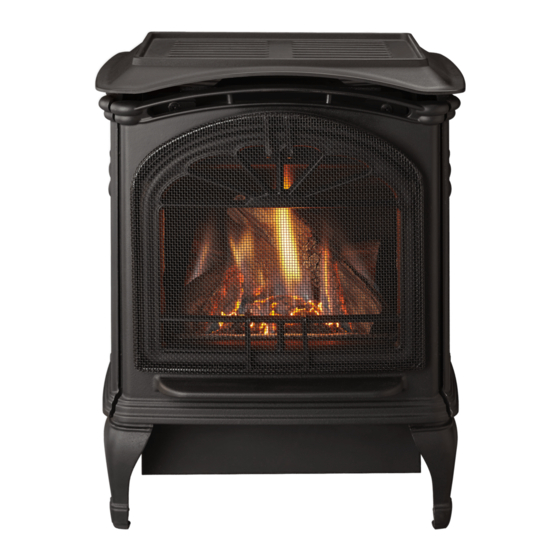
Model/Modèles:
Tiara Petite
AVERTISSEMENT: Assurez-vous de bien suivre les
instructions données dans cette notice pour réduire
au minimum le risque d'incendie ou d'explosion ou
pour éviter tout dommage matériel, toute blessure
ou la mort.
– Ne pas entreposer ni utiliser d'essence ni d'autres vapeurs
ou liquides inammables dans le voisinage de cet appareil
ou de tout autre appareil.
– QUE FAIRE SI VOUS SENTEZ UNE ODEUR DE GAZ
•
Ne tentez pas d'allumer d'appareil.
•
Ne touchez à aucun interrupteur. Ne pas vous servir
des téléphones se trouvant dans le bâtiment où vous
vous trouvez.
•
Évacuez la pièce, le bâtiment ou la zone.
•
Appelez immédiatement votre fournisseur de gaz depuis un
voisin. Suivez les instructions du fournisseur.
•
Si vous ne pouvez rejoindre le fournisseur de gaz, appelez le
service des incendies.
– L'installation et l'entretien doivent être assurés par un
installateur ou un service d'entretien qualifié ou par le
fournisseur de gaz. (Dans la République de Massachusetts,
l'installation doit être effectuêe par un plomier ou un
installateur d'appareils à gaz agrée.)
1. Cet appareil peut être utilisé dans un mobile
home, installé à demeure si les règlements locaux
le permettent.
2. Cet appareil ne peut être utilisé qu'avec le type
de gaz spécifié sur la plaque de caractéristiques.
Il n'est pas convertible et ne peut pas fonctionner
avec d'autres gaz que celui indiqué, à moins
qu'un ensemble homologué ne soit utilisé.
Dégagez la zone d'installation de l'appareil et éloignez
tout matériau combustible, essence et autre produit
ou gaz inflammable.
Ce chauffage peut être installé avec un système
d'évacuation directe à sortie horizontale ou verticale.
POUR VOTRE SÉCURITÉ
250-7471
November 15, 2002
Advertisement
Table of Contents

Subscribe to Our Youtube Channel
Related Manuals for Heat & Glo Tiara Petite


Summary of Contents for Heat & Glo Tiara Petite
- Page 1 Tested and O-T L Model/Modèles: Oregon USA Listed by Tiara Petite OMNI-Test Laboratories, Inc. AVERTISSEMENT: Assurez-vous de bien suivre les WARNING: If the information in these instructions instructions données dans cette notice pour réduire is not followed exactly, a fire or explosion may au minimum le risque d’incendie ou d’explosion ou...
-
Page 2: Table Of Contents
TABLE OF CONTENTS TABLE DES MATIÈRE Listings and Code Approvals ......... 3 ...........3 Homologations et normes Notices ..............3-4 ..................3-4 Avis Serial Label............. 5 ..............5 Numéro de série Safety Notices............6-7 ............. 6-7 Consignes de sécurité Overview of Installation ........... 8 .........8 Vue d'ensemble de l'installation Dimensions ............. -
Page 3: Listings And Code Approvals
LISTINGS AND CODE APPROVALS HOMOLOGATIONS ET NORMES L’appareil au gaz à évacuation directe Tiara Petite The Heat-N-Glo Tiara Petite Direct Vent Gas de Heat-N-Glo a été testé par la société OMNI- Appliance is listed to ANSI standard Z21.88b- Testing Laboratories, Inc., Beaverton, OR, selon la 2001/CSA 2.33b-01 Vented Gas Fireplace Heaters... -
Page 4: Notices
Canadian Electrical Code, CSA C22.1. ANSI/NFPA 70, ou au Code canadien d’électricité, CSA C22.1. The Heat-N-Glo Tiara Petite is manufactured to operate on Natural Gas (NG), it is field convertible to Liquid Propane (LP) Le modèle Tiara Petite de Heat-N-Glo est conçu pour using the manufacturer's conversion kit which is available from fonctionner au gaz naturel (GN). -
Page 5: Serial Label
(Attached to stove with beaded chain) (Étiquette attachée au poêle par une chaînette à boules) SERIAL NO. MODEL / MODÈLE: TIARA PETITE VENTED GAS FIREPLACE HEATER FOURNAISE AU GAZ AVEC VENTILATION Report No. / Rapport Numéro NOT FOR USE WITH SOLID FUEL / A division of Hearth Technologies Inc. -
Page 6: Safety Notices
SAFETY NOTICES CONSIGNES DE SÉCURITÉ À cause de la température élevée qu’il peut atteindre, Due to high temperatures, the appliance should l’appareil ne doit pas être situé dans un endroit be located out of traffic and away from furniture passant ni près de meubles ou de draperies. SAFETY NOTICES and draperies. - Page 7 SAFETY NOTICES CONSIGNES DE SÉCURITÉ (cont'd.) (suite) Do not use this appliance if any part has been N’utilisez jamais cet appareil si des pièces ont été under water. Immediately call a qualified service immergées. Appelez immédiatement un technicien technician to inspect the appliance and to replace qualifié...
-
Page 8: Overview Of Installation
OVERVIEW OF INSTALLATION TO PRÉSENTATION DE L’INSTALLATION ET DU FONCTIONNEMENT OPERATION • Familiarize yourself with this Owner's Manual and the • Lisez le manuel d’utilisation, ainsi que les consignes de sécurité contenues dans ce manuel et apposées sur Safety Notices located in this manual, and posted on the l’appareil à... -
Page 9: Dimensions
DIMENSIONS NOTE: Diagrams show gas stove equipped with optional Blower, Part #GFK-75. REMARQUE: Les schémas décrivent un poêle à gaz équipé d’un ventilateur en option, pièce n° GFK-75. 18 - 1/8 16 - 3/16 46 cm (18 1/8 PO) 18 - 1/8 41,1 cm (16 3/16 PO) 46cm (18 1/8 PO) 22 - 3/4... -
Page 10: Lp Gas Conversion Instructions
INSTRUCTIONS POUR LA CONVERSION AU PROPANE LP CONVERSION INSTRUCTIONS NOTE: Gas conversions should only be performed by a REMARQUE: Les conversions de gaz devrait étre uniquement qualified service person, and/or where required by state exécutées par une personne qualifiée, et/ou lorsque requis par des and local codes, licensed installer/service technician. -
Page 11: Valve Regulator Replacement
PLEASE NOTE: Logs have been designed to work ATTENTION: Les bûches ont été spécialement conçues specifically with the burner of the Tiara Petite. Exact pour le brûleur du modèle Tiara Petite. Leur positionnement placement will ensure proper operation of your gas exact assure le bon fonctionnement de votre appareil à... -
Page 12: Blower Kit Installation Instruction
LOG SET INSTALLATION INSTALLATION DES BÛCHES (cont'd.) (suite) Installation: Installation: 1. Gently remove top of unit and set aside. 1. Retirez délicatement la partie supérieure de l’unité et 2. Remove cast face by sliding straight up and set aside. mettez-la de côté. 3. -
Page 13: Warming Shelf Installation
BLOWER INSTALLATION INSTALLATION DU VENTILATEUR (cont'd.) (suite) Remove the (4) screws from the firebox and slide the Retirez les (4) vis du foyer et positionnez le ventilateur blower into place from the left side of the stove. en le faisant glisser par la gauche du poêle. Notez Notice the locations of the pilot assembly tubes and l’emplacement des fils et tubes de la veilleuse. -
Page 14: Thermostat Installation/Remote Control
INSTALLATION DU THERMOSTAT Un thermostat peut être installé pour réguler le modèle Tiara A thermostat may be installed to regulate the Tiara Petite. It is Petite. Il est important d’utiliser un thermostat conçu pour important to use a thermostat designed for millivolt operation. -
Page 15: General Venting Instructions
PRÉCAUTIONS D’INSTALLATION: result from any of the following actions: Installation of any Le modèle Tiara Petite de Heat-N-Glo est un produit usiné damaged venting component, unauthorized modification of qui a été mis au point et testé. Les actions suivantes peuvent the venting system, installation of any component part not causer un incendie, nuire à... -
Page 16: Installation Methods & Notes
D’INSTALLATION Quatre types d’installations de système à évacuation Four types of direct vent system installations are directe sont approuvés pour le modèle Tiara Petite. approved for use with the Tiara Petite. 1. Sortie horizontale (fig. 1, page 21) 1. Horizontal Termination (Fig. 1, page 21) 2. -
Page 17: Safety Precautions For The Installer
MÉTHODES ET REMARQUES D’INSTALLATION INSTALLATION METHODS & NOTES (suite) (cont'd.) 1. Dans le cas d’installations impliquant une conduite de 1. For installations with any horizontal vent run or horizontal ventilation horizontale ou une sortie horizontale, reportez- termination, refer to the Vent Graph on pages 26-27. vous au schéma illustrant le système de ventilation, pages This graph will show the relationship between vertical and 26-27. -
Page 18: Gaine Murale Hti Dv Pour Tuyau De Faible Diamètre
GAINE MURALE HTI DV POUR TUYAU HTI DV WALL THIMBLE DE FAIBLE DIAMÈTRE (cont'd.) (cont'd.) ASSEMBLING SLIM LINE TRIM RING & HEAT SHIELD ASSEMBLAGE DE LA RONDELLE DÉCORATIVE DU TUYAU À FAIBLE DIAMÈTRE et de l’ÉCRAN THERMIQUE 1. Choose the appropriate Trim Ring for your installation. 1. - Page 19 (3/4 po) entre les surfaces combustibles et la partie supérieure de l’écran thermique. Note: When installing the Tiara Petite to a rear wall in the Zero Clearance configuration remove the two heat shield knock-outs on the rear of the stove. See Fig. 5.
-
Page 20: Installation Methods
MÉTHODES D’INSTALLATION INSTALLATION METHODS Fig. A 90 DEGREE ELBOW Fig. B 45 DEGREE ELBOW COUDE À 90 DEGRÉS COUDE À 45 DEGRÉS Place mark where protrudes through exterior wall to cut TRIM RING SOLID OR VENTILATED/ off excess/Placez la marque où le thermique de écran SOLIDE D'ANNEAU D'ÉQUILIBRE OU AÉRÉ... - Page 21 INSTALLATION METHODS MÉTHODES D’INSTALLATION (cont'd.) (suite) FIG. 2 - VERTICAL TERMINATION FIG. 1 - HORIZONTAL TERMINATION Refer to pages 28-31 for installation instructions and Refer to page 23 for installation instructions and requirements requirements. On vertical terminations use only HTI SLK- FIG.
-
Page 22: Installation Methods
INSTALLATION METHODS (cont'd.) FIG.4 - A, B C & D INTO A MASONRY CHIMNEY (USA only) Refer to pages 33-34 for installation instructions and requirements. Type A & B Co-Axial to Co-Linear Part 923GCL Type A Type B himney Liner rmination Cap Part #923GK 30 ft of 3"... -
Page 23: Termination Requirements
HORIZONTAL TERMINATION EXIGENCES LIÉES À UNE SORTIE REQUIREMENTS HORIZONTALE = AREA WHERE TERMINAL IS NOT PERMITTED / ZONE OÙ LA MITRE EST INTERDITE = VENT TERMINAL / MITRE OP E NA B LE FIX E D CLO S E D = AIR SUPPLY INLET / (OUVR AB LE ) (CONDAMNÉ... -
Page 24: Horizontal Installations
HORIZONTAL INSTALLATIONS INSTALLATIONS HORIZONTALES Step 1. Determine the desired location of the stove. Check Étape 1. Déterminez l’emplacement désiré du poêle. to ensure that wall studs or roof rafters are not in the way Vérifiez et assurez-vous que les solives murales et les chevrons du toit ne gênent pas la fixation du système de when the venting system is attached. - Page 25 HORIZONTAL INSTALLATIONS INSTALLATIONS HORIZONTALES (cont'd) (suite) NOTE REMARQUE (2) The location of the horizontal vent termination on an exterior wall (2) L’emplacement de la sortie horizontale sur un mur extérieur doit être must meet all local and national building codes, and must not be conforme aux normes de construction locales et nationales, et ne pas easily blocked or obstructed, see page 24.
-
Page 26: Vent Graph
HORIZONTAL INSTALLATION INSTALLATIONS HORIZONTALES (cont'd.) (suite) FIG. 8-A FIG. 8-B TRIM HEAT SHIELD IF TOO LONG, VINYL SIDING/ HEAT SHIELD/ ADD TO SHIELD IF TOO SHORT./ REVÊTEMENT EN VINYLE ÉCRAN THERMIQUE COUPER L'ÉCRAN THERMIQUE S'IL EST TROP LONG ET LE RALLONGER APPLY SEALANT TO ALL FOUR S'IL EST TROP COURT. - Page 27 SCHÉMA ILLUSTRANT INSTALLATION VENT GRAPH L’INSTALLATION DE L’ÉVENT (cont'd.) (suite) Each 90° elbow is equivalent to 3' of vent pipe and each 45° 4. Chaque coude à 90° et 45° équivaut respectivement à 91 cm (3 pi) et à elbow is equivalent to 1' of vent pipe, and must be subtracted 30,50 cm (1 pi) de tuyau d’évent.
-
Page 28: Vertical Installation
DAMPER INSTALLATION AND INSTALLATION ET RÉGLAGE D’UN ADJUSTMENT REGISTRE DE TIRAGE WHEN YOUR INSTALLATION FALLS WITHIN A SHADED AREA ON SI VOTRE INSTALLATION SE SITUE DANS LA ZONE OMBRÉE DU THE VENT GRAPH (PAGE 26-27) A DAMPER MUST BE INSTALLED SCHEMA (PAGE 26-27), VOUS DEVEZ INSTALLER UN REGISTRE DE FOR PROPER OPERATION. -
Page 29: Using Gs Series Pipe
VERTICAL INSTALLATION INSTRUCTIONS D'INSTALLATION INSTRUCTIONS VERTICALE (cont'd.) (suite) USING GS SERIES PIPE UTILISATION DE TUYAUX DE SÉRIE GS (cont'd.) (suite) Fig. 10 Fig. 11 PLUMBER'S TAPE CONNECTED TO WALL STRAP/ Ruban adhésif de plomberie fixé à la patte MAXIMUM/ 10,70 m (35 pi) WALL STRAP MAXIMUM Patte Murale... -
Page 30: Roof Pitch Table
INSTRUCTIONS D’INSTALLATION VERTICAL INSTALLATION VERTICALE INSTRUCTIONS (suite) (cont'd.) USING GS SERIES PIPE UTILISATION DE TUYAUX DE SÉRIE GS (cont'd.) (suite) NOTE: REMARQUE: (1) Si une déviation est nécessaire dans le grenier pour ) If an offset is necessary in the attic to avoid obstructions, contourner un obstacle, il est important de soutenir le tuyau it is important to support the vent pipe every 3’... -
Page 31: Cathedral Ceiling Installation
INSTALLATION VERTICALE VERTICAL INSTALLATION (suite) (cont'd.) Step 8. Étape 8. NAILS Twist-lock the vent cap and seal. CLOUS Emboîtez le capuchon d’évent et NOTE: CEILING FIRESTOP scellez-le. PLAFOND COUPE-FEU (1) For multi-story vertical installations, a Remarque: ceiling firestop is required at the second (1) Pour les installations ver ticales floor, and any subsequent floors (Fig. -
Page 32: Class A Metal Chimney
VERTICAL INSTALLATION INSTALLATION VERTICALE (cont'd.) (suite) CATHEDRAL CEILING INSTALLATION INSTALLATION POUR TOIT CATHÉDRALE (cont'd) (suite) Étape 6. Step 6. Terminez l’installation du plafond cathédrale en suivant les Complete the cathedral ceiling installation by following the procédures décrites aux étapes 4 à 8, aux pages 29-31 de same procedures outlined in steps 4 through 8 for vertical la section relatives aux sorties verticales. -
Page 33: Existing Masonry Chimey
VERTICAL INSTALLATION (cont'd.) INSTALLATION INTO AN EXISTING MASONRY CHIMNEY (USA ONLY) Step 1. Before cutting any holes, assemble the desired sections of direct vent pipe to determine the center of the FIG. 21 STUDWALL/ masonry penetration. CLOISON 10" x 10" FRAMED LATTÉE ET OPENING IN WALL/ PLÂTRÉE... -
Page 34: Gas Line Requirements
VERTICAL INSTALLATION (cont'd.) INSTALLATION INTO AN EXISTING MASONRY CHIMNEY (USA ONLY) (cont'd.) Step 11. The connection between the appliance and the retro connector may be completed with sections of direct vent pipe. WARNING: If any other appliances have been previously attached to this masonary flue or an open fireplace, etc., all openings into flue should be sealed properly. -
Page 35: Checking Gas Inlet Pressure
EXIGENCES RELATIVES À LA CONDUITE DE GAZ GAS LINE REQUIREMENTS GAS LINE CONNECTION RACCORD DE LA CONDUITE DE GAZ (cont'd.) (suite) Connect the gas line at the 3/8” pipe connector on the valve at the back of Branchez la conduite de gaz au raccord de 95 mm (3/8 po) qui se trouve stove. -
Page 36: Leak Test
LEAK TEST TEST D’ÉTANCHÉITÉ 1. Ouvrez le gaz alimentant le foyer. 1. Turn on gas to the fireplace. 2. Ouvrez le robinet de gaz manuel. 2. Turn on gas at the manual shutoff valve. 3. Utilisez un détecteur de fuites pour vérifier l’étanchéité de tous 3. -
Page 37: Lighting Instructions
LIGHTING INSTRUCTIONS FOR YOUR SAFETY READ BEFORE LIGHTING WARNING: If you do not follow these instructions exactly, a fire or explosion may result causing property damage, personal injury or loss of life A. This appliance has a pilot that must be lit manually. When lighting the pilot, follow these instructions exactly. B. -
Page 38: Instructions D'allumage
INSTRUCTIONS D’ALLUMAGE (Version Française) POUR VOTRE SÉCRUITÉ, LIRE AVANT D'ALLUMER ADVERTISSEMENT: Si vous ne suivez pas exactment ces instructions, un few ou une explosion peuvent surenir et causer des dommages a votre propriété, des blessures corporelles ou méme uneperte de vie. A. -
Page 39: High Altitude Operation Adjustment
FONCTIONNEMENT À HAUTE HIGH ALTITUDE OPERATION ALTITUDE In Canada, this unit is approved from 0 to 4500 feet above Au Canada, cette unité est approuvée pour des altitudes sea level. Installation of this stove at altitudes above 4500 allant de 0 à 1371 m (de 0 à 4500 pieds) au-dessus du feet is subject to field test of the individual installation and niveau de la mer. -
Page 40: Operating Procedures
PROCÉDURES D’UTILISATION OPERATING PROCEDURES Read this entire manual prior to using the appliance. Lisez ce manuel en entier avant d’utiliser le foyer. Pay particular attention to the “Safety Notices” section Portez une attention toute particulière aux consignes on pages 6 & 7. Failure to follow the instructions may de sécurité... -
Page 41: Maintenance
ENTRETIEN MAINTENANCE L’installation et la réparation ne doivent être effectuées que Installation and repair should be done only by a qualified par une entreprise de maintenance qualifiée. L’appareil et service agency. The appliance and venting systems should son système de ventilation doivent être inspectés avant be inspected before use and at least annually by a qualified utilisation et au moins une fois l’an par une entreprise agency. -
Page 42: Yearly Maintenance
YEARLY MAINTENANCE PROCÉDURES D’ENTRETIEN ANNUEL PROCEDURES (suite) (cont'd) 3. Shut off gas to the stove by turning the valve control 3. Coupez l’alimentation en gaz du poêle en tournant knob to “OFF” and turning off the manual shutoff valve. le bouton de commande de la soupape sur “OFF“ et en Allow the stove to cool for 15 minutes. -
Page 43: Ignition Module And Battery Replacement
This module was incorporated into sur le côté gauche du poêle. Ce module a été incorporé the design of the Tiara Petite to facilitate "one hand" dans la conception du modèle Tiara Petite an de faciliter lighting of the stove. -
Page 44: Electrical Schematic
250-7471 November 15, 2002 Page 44... -
Page 45: Troubleshooting
TROUBLE SHOOTING DÉPANNAGE Pilot Will Not Light Le pilote ne s’allume pas. 1. Is gas shut-off valve turned on? 1. Le robinet de gaz est-il ouvert? 2. Is the valve control knob turned to “PILOT” (See Lighting 2. Le bouton de commande de la soupape est-il en position “PILOT“? Instructions, #7, Pg. - Page 46 TROUBLE SHOOTING DÉPANNAGE (cont'd.) (suite) Pilot Goes Out Once a Month or More Le pilote s'éteint une fois par mois ou plus (cont'd.) (suite). 2. Build-up on pilot assembly 2. Un dépôt obstrue-t-il la veilleuse? 3. La pression d’alimentation est-elle correcte? 3.
-
Page 47: Éléments De Ventilation Directe De La Série Sl-D
Heat-N-Glo Tiara Petite has been approved with SL-D Series, Dura-Vent Venting Systems and Security Chimney's Le poêle Tiara Petite de Heat-N-Glo a été homologué avec son Secure Vent Chimney System. All the required certification dispositif d’évacuation des fumées SL-D Series, Dura-Vent et tests have been successfully completed with OMNI-Testing Security Chimney. -
Page 48: Sl D-Series Direct Vent Components
SL-D SERIES DIRECT VENTING COMPONENTS (cont'd.) ÉLÉMENTS DE VENTILATION DIRECTE DE LA SÉRIE SL-D (suite) TERMINATION KITS KITS DES TERMINER SLK-01D Horizontal Round Termination Kit 7 3/4" SLK-01D Kit de mitre ronde 7 3/4"-11", 2 coupe-feu SLK-01TRD Kit de mitre trapézoïd 7 3/4" - 11", 2 -11", 2 Firestops coupe-feu SLK-01TRD... -
Page 49: Parts & Accessories
(NG, LP) SERVICE PARTS LIST/LISTE DES PIÈCES DE RECHANGE TIARA PETITE IMPORTANT: THIS IS DATED INFORMATION. The most current information is located on your dealer's VIP site. When ordering, supply serial and model numbers to ensure correct service parts. / IMPORTANT: L'information fournie dans cette brochure n'est valide que pendant une courte période. -
Page 50: Exploded View Parts
EXPLODED VIEW-SERVICE PARTS SCHÉMA ÉCLATÉ-PIÈCES DE RECHANGE 250-7471 November 15, 2002 Page 50... -
Page 51: Warranty
Lifetime Warranty LIMITED LIFETIME WARRANTY The Hearth & Home Technologies limited Lifetime Warranty guarantees that the following components will work as designed for the lifetime of the stove or Hearth & Home Technologies will repair or replace them. These items include but are not limited to steel and cast iron components, all gas burners, gas logs, combustion chambers, heat exchanger systems, stainless steel firebox components, gold plating, doors, glass damaged by thermal breakage, steel baffle supports, steel and ceramic baffles and manifold tubes. - Page 52 ATTENTION INSTALLER: PLEASE RETURN THESE OPERATING & INSTALLATION INSTRUCTIONS TO THE CONSUMER. AVIS À L’INSTALLATEUR: VEUILLEZ REMETTRE CES INSTRUCTIONS D’INSTALLATION ET D’UTILISATION AU CLIENT. 250-7471 November 15, 2002 Page 52...
Need help?
Do you have a question about the Tiara Petite and is the answer not in the manual?
Questions and answers