Intel G31 User Manual
Express chipset, ich chipset based m/b for lga 775 quad core ready intel core processor family
Hide thumbs
Also See for G31:
- Specification (12 pages) ,
- User manual (39 pages) ,
- User manual (33 pages)
Table of Contents
Advertisement
Quick Links
、
USER'S MANUAL
Of
Intel G31 Express Chipset
&
Intel FW82801GB ICH Chipset
Based
M/B For LGA 775 Quad Core Ready
Intel Core Processor Family
No. G03-I31GM3-F
Rev: 3.0
Release date: July, 2008
Trademark:
* Specifications and Information contained in this documentation are furnished for information use only, and are
subject to change at any time without notice, and should not be construed as a commitment by manufacturer.
Advertisement
Table of Contents

Subscribe to Our Youtube Channel
Related Manuals for Intel G31


Summary of Contents for Intel G31
- Page 1 、 USER'S MANUAL Intel G31 Express Chipset & Intel FW82801GB ICH Chipset Based M/B For LGA 775 Quad Core Ready Intel Core Processor Family No. G03-I31GM3-F Rev: 3.0 Release date: July, 2008 Trademark: * Specifications and Information contained in this documentation are furnished for information use only, and are...
-
Page 2: Table Of Contents
TABLE OF CONTENT CHAPTER 1 INTRODUCTION OF INTEL G31 MOTHERBOARD SERIES FEATURES OF MOTHERBOARD ..................1 1-1.1 SPECIAL FEATURES OF MOTHERBOARD............ 2 SPECIFIC A TION........................3 ITEM CHECKLIST ......................4 LAYOUT DIAGRAM & JUMPER SETTING ..............4 CHAPTER 2 HARDWARE INSTALLATION INSTALL LGA 775 SUPPORTED INTEL PROCESSOR.......... -
Page 3: Chapter 1 Introduction Of Intel G31 Motherboard Series
Introduction of Intel G31 Motherboard Series 1-1 Features of motherboard The Intel G31 chipset motherboard series are based on the latest Intel G31 Express Chipset and Intel FW82801GB ICH Chipset technology which supports the innovative 65nm and 90nm Intel® Pentium® 4 Processor,... -
Page 4: 1-1.1 Special Features Of Motherboard
Embedded USB controller as well as capability of expanding to 8 of USB2.0 functional ports delivering 480Mb/s of rich connectivity, these motherboards meet the demands of future USB peripherals which are also equipped with hardware monitor function on system to monitor and protect your system and maintain your non-stop business computing. -
Page 5: Specification
Chipset ∗ Intel 82801GB I/O Controller Hub (ICH7) Chipset ∗ Support Intel Pentium 4, Celeron 4xx, Pentium D, Core 2 Duo and Core 2 CPU Socket Quad 775-Land LGA Package utilizes Flip-Chip Land Grid Array (LGA775 ) (FCLGA) package processor ∗... -
Page 6: Item Checklist
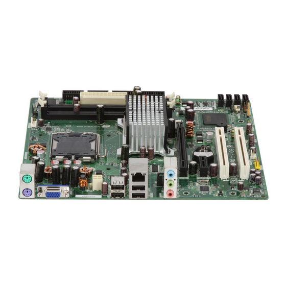
Item Checklist Intel G31 Platform Processor Chipset based motherboard Cable for IDE CD for motherboard utilities Cable for Serial ATA Port Intel G31 Platform Processor Chipset motherboard User’s Manual Layout Diagram & Jumper Setting KB/MS Power ON Jumper (JP1) CPU Socket mPGA775... -
Page 7: Chapter 2 Hardware Installation
Install LGA 775 Supported Intel Processor This motherboard provides a 775-pin surface mount, LGA775 Land Grid Array socket, referred to as the LGA775 socket supports Intel Pentium 4 processor in the 775 Pin package utilizes Flip-Chip Land Grid Array (FC-LGA) package technology. -
Page 8: Expansion Cards
2-3 Expansion Cards The G31 motherboard series offer one PCI-Express x16 graphics slot of 4Gbyte/sec data transfer rate at each relative direction which gets 3.5 times of bandwidth more than AGP 8X and it’s up to a peak concurrent bandwidth of 8Gbyte/sec at full speed to guarantee the ultimate GPU computing performance. -
Page 9: Connectors
PE1 / PCI-E x16 Slot PE2 / PCI-E x1 Slot 32-bit PCI Slots Chapter 3 Connectors, Headers & Jumpers Setting 3-1 Connectors Power Connector (24-pin block) : ATXPWR Power Supply connector: This is a new defined 24-pins ROW1 ROW2 connector that usually comes with ROW1 ROW2 ROW1 ROW2... - Page 10 ** If you intend to use a PSU with 20-pin and 4-pin power plugs, make sure that the 20-pin power plug can provide at least 15A on +12V and the power supply unit has a minimum power rating of 350W. The system may become unstable or may not boot up if the power is inadequate.
-
Page 11: Headers
IDE1 IDE1 (8) Primary IDE Connector (40-pin block): IDE This connector connects to the next set of Master and Slave hard disks. Follow the same procedure described for the primary IDE connector. You may also configure two hard disks to be both Masters using one ribbon cable on the primary IDE connector and another ribbon cable on the secondary IDE connector. - Page 12 (2) USB Port Headers (9-pin) : USB3 USB2 USB2 / USB3 These headers are used for connecting the additional USB port plug. By attaching an Pin 1 Pin 1 option USB cable, your can be provided with two additional USB plugs affixed to the back panel.
- Page 13 (9) CD Audio-In Headers (4-pin) : CDIN CDIN CDIN are the connectors for CD-Audio Input signal. Please connect it to CD-ROM CD-Audio output connector. CD Audio-In Headers (10) Parallel Port header (25-pin): PARALLEL The On-board Parallel Port can be disabled through the BIOS SETUP.
-
Page 14: Chapter 4 Useful Help
STEP 2. Copy utility program to your boot disc. You may copy from DRIVER CD X:\FLASH\AWDFLASH.EXE or download from our web site. STEP 3. Download and make a copy of the latest BIOS for G31 motherboard series from the web site to your boot disc.
Need help?
Do you have a question about the G31 and is the answer not in the manual?
Questions and answers