Intel G41 User Manual
Chipset based m/b for lga 775 quad core ready intel core processor family
Hide thumbs
Also See for G41:
- User manual (19 pages) ,
- Simplified user manual (7 pages) ,
- Thermal/mechanical design manuallines (44 pages)
Table of Contents
Advertisement
USER'S MANUAL
Of
Intel G41 Express Chipset
&
Intel ICH7 Chipset
Based
M/B for LGA 775 Quad Core Ready
Intel Core Processor Family
No. G03-MI5G41SGMD2F
Rev: 5.0
Release date: Nov., 2009
Trademark:
* Specifications and Information contained in this documentation are furnished for information use only, and are
subject to change at any time without notice, and should not be construed as a commitment by manufacturer.
Advertisement
Table of Contents

Related Manuals for Intel G41


Summary of Contents for Intel G41
- Page 1 USER'S MANUAL Intel G41 Express Chipset & Intel ICH7 Chipset Based M/B for LGA 775 Quad Core Ready Intel Core Processor Family No. G03-MI5G41SGMD2F Rev: 5.0 Release date: Nov., 2009 Trademark: * Specifications and Information contained in this documentation are furnished for information use only, and are...
- Page 2 Environmental Safety Instruction Avoid the dusty, humidity and temperature extremes. Do not place the product in any area where it may become wet. 0 to 40 centigrade is the suitable temperature. (The figure comes from the request of the main chipset) Generally speaking, dramatic changes in temperature may lead to contact malfunction and crackles due to constant thermal expansion and contraction from the welding spots’...
-
Page 3: Table Of Contents
TABLE OF CONTENT CHAPTER 1 INTRODUCTION OF INTEL G41 MOTHERBOARD SERIES FEATURES OF MOTHERBOARD ................1 1-1.1 SPECIAL FEATURES OF MOTHERBOARD ..........2 SPECIFICATION ......................3 ITEM CHECKLIST....................... 4 LAYOUT DIAGRAM....................4 CHAPTER 2 HARDWARE INSTALLATION INSTALL LGA 775 SUPPORTED INTEL PROCESSOR........... 6 INSTALL MEMORY .................... -
Page 4: Chapter 1 Introduction Of Intel G41 Motherboard Series
Introduction of Intel G41 Motherboard Series 1-1 Features of motherboard The Intel G41 chipset motherboard series are based on the latest Intel G41 Express Chipset and Intel ICH7 Chipset technology which supports the innovative 65nm and 90nm Intel® Pentium® Dual Core Processor, Intel® Core 2 Quad, Intel® Core 2 Duo®... -
Page 5: 1-1.1 Special Features Of Motherboard
be careful and make sure to read the detailed descriptions of these value added product features, please get them in the coming section. 1-1.1 Special Features of Motherboard CPU Thermal Throttling Technology ---(The CPU Overheat Protection Technology) To prevent the increasing heat from damage of CPU or accidental shutdown while at high workload, the CPU Thermal Throttling Technology will force CPU to enter partially idle mode from 87.5% to 12.5% according to preset CPU operating temperature in BIOS (from 40℃... -
Page 6: Specification
Intel G41 Memory Controller Hub (MCH) Chipset Intel 82801GB I/O Controller Hub (ICH7) Chipset Supports the innovative 65nm and 90nm Intel® Pentium® Dual Core Processor , Intel® Core 2 Quad, Intel® Core 2 Duo® (Code Name: CPU Socket Conroe) Processor with Intel® Hyper-Threading Technology and (LGA775 ) fully supports the future 45nm processors. -
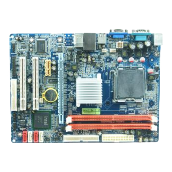
Page 7: Item Checklist
Item Checklist Intel G41 Platform Processor Chipset based motherboard DVD for motherboard utilities Hard disk cable User’s Manual Back panel Layout Diagram Diagram is for MI5-G41SGMD2-LF KB/MS Power ON Jumper (JP1) CPU Socket mPGA775 PS2 KB/Mouse Port ATX 12V Power... - Page 8 CPU FAN SYSFAN1 USB Port USB Power ON Jumper (JP2) RJ45 Over USB Port IDE Connector 6-CH Audio Connector Intel G41Express Chipset Megabit LAN Chip Front Panel Header PCI Express x16 Power Led & PCI Express x1 Speaker Header Serial-ATA2...
-
Page 9: Chapter 2 Hardware Installation
Install LGA 775 Supported Intel Processor This motherboard provides a 775-pin surface mount, LGA775 Land Grid Array socket, referred to as the LGA775 socket supports Intel Pentium Dual Core processor in the 775 Pin package utilizes Flip-Chip Land Grid Array (FC-LGA) package technology. - Page 10 Model MI5-G41SGMD3-LF provides two 240-pin DDR3 DUAL INLINE MEMORY MODULES (DIMM) socket for DDR3 memory expansion to maximum memory volume of 8GB DDR3 SDRAM. Valid Memory Configuration for MI5-G41SGMD3-LF Bank 240-Pin DIMM Total Memory Bank 0, 1 (DIMM1) DDR3 800/ DDR3 1066 Bank 2, 3 (DIMM2) DDR3 800/ DDR3 1066 Total...
-
Page 11: Expansion Cards
2-3 Expansion Cards The G41 motherboard series offer one PCI-Express x16 graphics slot of 8Gbyte/sec data transfer rate at each relative direction which gets 7 times of bandwidth more than AGP 8X and it’s up to a peak concurrent bandwidth of 16Gbyte/sec at full speed to guarantee the ultimate GPU computing performance. -
Page 12: Connectors
Chapter 3 Connectors, Headers & Jumpers Setting 3-1 Connectors Power Connector (24-pin block): ATXPWR ATX Power Supply connector: This is a new defined 24-pins ROW1 ROW2 connector that usually comes ROW1 ROW2 ROW1 ROW2 3.3V 3.3V with ATX case. The ATX Power 3.3V -12V Supply allows using soft power... - Page 13 (3) PS/2 Mouse & PS/2 Keyboard Connector: KB1 The connectors are for PS/2 keyboard and PS/2 Mouse. (4) USB Port connector: USB1, UL1 The connectors are 4-pin connectors that connect USB devices to the system board. (5) LAN Port connector: UL1 This connector is standard RJ45 connector for Network.
- Page 14 Two hard disks can be connected to each connector. The first HDD is referred to as the “Master” and the second HDD is referred to as the “Slave”. For performance issues, we strongly suggest you don’t install a CD-ROM or DVD-ROM drive on the same IDE channel as a hard disk.
-
Page 15: Headers
3-2 Headers (1) Line-Out/MIC Header for Front Panel (9-pin): AUDIO This header is connected to Front Panel Line-out, MIC connector with cable. AUDIO Pin 1 Line-Out, MIC Headers (2) USB Port Headers (9-pin) : USB2 / USB3 These headers are used for connecting the additional USB port plug. attaching an option USB cable, your can be provided with two additional USB plugs affixed to the back panel. - Page 16 (6) Reset switch lead: RESET This 2-pin connector connects to the case-mounted reset switch for rebooting your computer without having to turn off your power switch. This is a preferred method of rebooting in order to prolong the lift of the system’s power supply. See the figure below.
- Page 17 (9) CD Audio-In Headers (4-pin): CDIN CDIN are the connectors for CD-Audio Input signal. Please connect it to CD-ROM CD-Audio output connector. CDIN CD Audio-In Headers (10) Parallel Port header (25-pin): PARALLEL The On-board Parallel Port can be disabled through the BIOS SETUP. . Pin 1 PARALLEL Connector (11) SPDIF Out header: SPDIF Out...
-
Page 18: Jupper Setting
3-3 Jumper Setting Keyboard/Mouse Power-on Enabled/Disabled: JP1 1-2 Closed KB/MSPower ON Disable (Default) 2-3 Closed KB/MS Power ON Enabled Keyboard/Mouse Power On Setting USB Power-on Enabled/Disabled: JP3 1-2 Closed: USB Power On Disable (Default) 2-3 Closed: USB Power On Enabled USB Power On Setting (3) CMOS RAM Clear (3-pin): JBAT A battery must be used to retain the motherboard configuration in CMOS RAM... - Page 19 For MI5-G41SGMD2-LF JBAT JBAT 1-2 Closed Normal 2-3 Closed Clear CMOS CMOS RAM Clear Setting NOTE! JBAT for MI5-G41SGMD3-LF has only 2-pin. To clear CMOS user needs to short 1-2pins. The normal state is to leave Pin 1-2 open.
-
Page 20: Chapter 4 Useful Help
Chapter 4 Useful Help 4-1 How to Update BIOS Step 1. Prepare a bootable disc. (You may make one by click START click RUN type SYS A: click OK) Step 2. Download upgrade tools and the latest BIOS files of the motherboard from official website and then make a copy of it to your bootable disk after decompressing these files Step 3.
Need help?
Do you have a question about the G41 and is the answer not in the manual?
Questions and answers