Dell OptiPlex 320 User Manual
Hide thumbs
Also See for OptiPlex 320:
- Quick reference manual (356 pages) ,
- Tech specs (6 pages) ,
- Quick reference manual (266 pages)
Table of Contents
Advertisement
Advertisement
Table of Contents

Related Manuals for Dell OptiPlex 320


Summary of Contents for Dell OptiPlex 320
- Page 1 Dell™ OptiPlex™ 320 User's Guide Mini Tower Computer Desktop Computer ...
-
Page 2: Advanced Features
(alerts), and security for computers equipped with industry-standard management software. It supports instrumentation that conforms to SNMP, DMI, and CIM industry standards. Dell OpenManage Client instrumentation, which is based on DMI and CIM, is available for your computer. For information on IT Assistant, see the Dell OpenManage IT Assistant User's Guide available on the Dell Support website at support.dell.com. -
Page 3: Password Protection
Password Protection NOTICE: Although passwords provide security for the data on your computer, they are not foolproof. If your data requires more security, it is your responsibility to obtain and use additional forms of protection, such as data encryption programs. ... -
Page 4: Deleting Or Changing An Existing System Password
If you type a wrong or incomplete system password, the following message appears on the screen: ** Incorrect password. ** If you again type an incorrect or incomplete system password, the same message appears on the screen. The third and subsequent times you type an incorrect or incomplete system password, the computer displays the following message: ** Incorrect password. -
Page 5: Disabling A Forgotten Password And Setting A New Password
1. Turn on (or restart) your computer. 2. When the blue DELL™ logo appears, press <F2> immediately. If you wait too long and the operating system logo appears, continue to wait until you see the Microsoft® Windows® desktop. Then shut down your computer and try again (see Turning Off Your Computer). -
Page 6: System Setup Options
Key Functions — This field appears below the Option Field and lists keys and their functions within the active system setup field. System Setup Options NOTE: Depending on your computer and installed devices, the items listed in this section may or may not appear. System Lists the computer name, BIOS Version, Service Tag, Express Service Code, (if applicable), and the Asset Tag. - Page 7 (On default) Determines the mode of operation of the internal parallel port. Off disables the port. AT configures the port for AT compatibility. PS/2 LPT Port configures the port for PS/2 compatibility. EPP configures the port for the EPP bidirectional protocol. ECP configures the port for the ECP Mode bidirectional protocol.
-
Page 8: Boot Sequence
password from being able to modify the System password. Unlocked allows a user with a valid System password to modify the system Changes password. (Unlocked default) Enables or disables Execute Disable memory protection technology. Execute Disable (On default) Power Management Determines how the system responds when AC power is re-applied after a power loss. -
Page 9: Booting To A Usb Device
Changing Boot Sequence for the Current Boot You can use this feature, for example, to tell the computer to boot from the CD drive so that you can run the Dell Diagnostics on the Drivers and Utilities CD (ResourceCD), but you want the computer to boot from the hard drive when the diagnostic tests are complete. You can also use this feature to restart your computer to a USB device such as a floppy drive, memory key, or CD drive. -
Page 10: Clearing Forgotten Passwords
3. From the boot menu, select the number that appears next to the USB device. The computer boots to the USB device. Floppy Drive 1. In system setup, set the Diskette Drive option to USB. 2. Save and exit system setup. ... -
Page 11: Clearing Cmos Settings
7. Disconnect the computer power cable from the electrical outlet, and press the power button to ground the system board. 8. Remove the computer cover. 9. Locate the 3-pin password jumper on the system board and move the jumper from pins 2 and 3 to pins 1 and 2 to reenable the password feature. ... - Page 12 NOTE: All components installed in the computer must support the hibernate and/or standby mode feature(s) and have the appropriate drivers loaded to enter either of these sleep modes. For more information, see the manufacturer's documentation for each component. Standby. In this sleep mode, power is reduced or turned off for most components, including the cooling fans. However, system memory remains active. Hibernate.
- Page 13 Back to Contents Page Battery Dell™ OptiPlex™ 320 User's Guide CAUTION: Before you begin any of the procedures in this section, follow the safety instructions in the Product Information Guide. NOTICE: To prevent static damage to components inside your computer, discharge static electricity from your body before you touch any of your computer's electronic components.
- Page 14 3 battery socket tab 4 battery socket NOTICE: To avoid damage to the battery connector, you must firmly support the connector while replacing the battery. 5. Install the new system battery. a. Support the battery connector by pressing down firmly on the positive side of the connector. b.
-
Page 15: Before You Begin
Hold a component such as a processor by its edges, not by its pins. NOTICE: Only a certified service technician should perform repairs on your computer. Damage due to servicing that is not authorized by Dell is not covered by your warranty. - Page 16 2. Disconnect any telephone or telecommunication lines from the computer. 3. Disconnect your computer and all attached devices from their electrical outlets, and then press the power button to ground the system board. 4. If applicable, remove the computer stand (for instructions, see the documentation that came with the stand). ...
-
Page 17: Cleaning Your Computer
Back to Contents Page Cleaning Your Computer Dell™ OptiPlex™ 320 User's Guide CAUTION: Before you begin any of the procedures in this section, follow the safety instructions located in the Product Information Guide. Computer, Keyboard, and Monitor CAUTION: Before you clean your computer, disconnect the computer from the electrical outlet. Clean your computer with a soft cloth dampened with water. - Page 18 some protection from dust, fingerprints, and scratches. Cleaning products for CDs are safe to use on DVDs. Back to Contents Page ...
-
Page 19: Connecting Multiple Monitors
Back to Contents Page Connecting Multiple Monitors Dell™ OptiPlex™ 320 User's Guide Before Connecting Mutiple Monitors or a Monitor and a Television to Your Computer Connecting Two to Three Monitors Using Surround View Connecting Dual Monitors or a Monitor and a Television to a Graphics Card Changing the Display Settings... -
Page 20: Changing The Display Settings
3. Make the appropriate connections for the second device that you are connecting. DVI monitor: Connect the DVI connector on the monitor to the DVI (white) connector on the graphics card in the back of the computer. VGA monitor: Connect the VGA connector on the monitor to the optional DVI adapter and then connect the adapter to the DVI (white) connector on the graphics card in the back of the computer. -
Page 21: About Your Desktop Computer
If your operating system has ACPI enabled, when you press the power button the computer will perform an operating system shutdown. Dell badge This badge can be rotated to match the orientation of your computer. To rotate the badge, place your fingers around the outside of the badge, press firmly, and turn the badge. -
Page 22: Back View
10 CD/DVD drive Insert a CD or DVD (if supported) into this drive. 11 location of Use the Service Tag to identify your computer when you access the Dell Service Tag Support website or call technical support. Back View 1 card slots Access connectors for any installed PCI and PCI Express cards. -
Page 23: Inside Your Computer
NOTE: Do not plug a telephone cable into the network connector. On computers with a network adapter card, use the connector on the card. It is recommended that you use Category 5 wiring and connectors for your network. If you must use Category 3 wiring, force the network speed to 10 Mbps to ensure reliable operation. -
Page 24: System Board Components
System Board Components 1 fan connector (FAN) 10 internal buzzer (SPKR1) 2 processor connector (CPU) 11 password jumper (PSWD) 3 processor power connector (12VPOWER) 12 real time clock reset jumper (RTCRST) 4 front-panel connector (FNT_PANEL) 13 battery socket (BATT) 5 memory module connectors (DIMM_1, DIMM_2) 14 PCI Express x16 card connector 6 serial ATA drive connectors (SATA0, SATA1) 15 PCI card connector (2) 7 power connector (POWER) -
Page 25: Pci And Pci Express Cards
To prevent static damage to components inside your computer, discharge static electricity from your body before you touch any of your computer's electronic components. You can do so by touching an unpainted metal surface on the computer chassis. Your Dell™ computer provides two low-profile PCI card slots for PCI cards and one card slot for a low-profile PCI Express card: NOTE: Your Dell computer uses only PCI and PCI Express slots. -
Page 26: Removing An Expansion Card
6. Place the card in the connector and press down firmly. Ensure that the card is fully seated in the slot. card fully seated card not fully seated bracket within slot bracket caught outside of slot 7. Gently press down on the card retention latch to secure the card. NOTICE: Do not route card cables over or behind the cards. - Page 27 5. If you are removing the card permanently, install a filler bracket in the empty card-slot opening. If you need a filler bracket, contact Dell (see Contacting Dell). NOTE: Installing filler brackets over empty card-slot openings is necessary to maintain FCC certification of the computer. The brackets also keep dust and dirt out of your computer.
-
Page 28: Removing The Processor
Back to Contents Page Processor Dell™ OptiPlex™ 320 User's Guide Removing the Processor Installing the Processor CAUTION: Before you begin any of the procedures in this section, follow the safety instructions located in the Product Information Guide. NOTICE: To prevent static damage to components inside your computer, discharge static electricity from your body before you touch any of your computer's electronic components. -
Page 29: Installing The Processor
1 center cover latch 2 processor cover 3 processor 4 socket 5 release lever NOTICE: When replacing the processor, do not touch any of the pins inside the socket or allow any objects to fall on the pins in the socket. ... - Page 30 Ensure that the tab on the processor cover is positioned underneath the center cover latch on the socket. 8. Pivot the socket release lever back toward the socket, and snap it into place to secure the processor. 9. Clean the thermal grease from the bottom of the heat sink. NOTICE: Ensure that you apply new thermal grease.
-
Page 31: General Installation Guidelines
Back to Contents Page Drives Dell™ OptiPlex™ 320 User's Guide Drives General Installation Guidelines CD/DVD Drive Floppy Drive Hard Drive Your computer supports: One SATA (serial ATA) hard drive One optional floppy drive One optional CD or DVD drive 1 CD/DVD drive 2 floppy drive 3 hard drive General Installation Guidelines... -
Page 32: Cd/Dvd Drive
Connect an IDE CD/DVD drive to the connector labeled "IDE" on the system board. Connect a SATA CD/DVD drive to the connector labeled "SATA1." SATA hard drives should be connected to the connectors labeled "SATA0" or "SATA1" on the system board. To locate system board connectors, see System Board Components. -
Page 33: Installing A Cd/Dvd Drive
1. Follow the procedures in Before You Begin. NOTICE: Do not pull the drive out of the computer by the drive cables. Doing so may cause damage to cables and the cable connectors. 2. Pull up on the drive release latch and slide the drive towards the back of the computer. Then, lift up to remove the drive from the computer. 1 drive release latch 2 CD/DVD drive ... -
Page 34: Removing A Floppy Drive
8. Update your configuration information by setting the appropriate Drive option (0 or 1) under Drives. See System Setup for more information. 9. Verify that your computer works correctly by running the Dell Diagnostics (see Dell Diagnostics). Floppy Drive ... -
Page 35: Installing A Floppy Drive
1 drive release latch 2 floppy drive 4. Disconnect the power and data cables from the back of the floppy drive. Installing a Floppy Drive 1. If you are installing a new drive: a. Gently slide a small flat-edge screw driver between the front of the computer and the back side of the drive-panel insert to pop off the insert. b. -
Page 36: Removing A Hard Drive
9. Enter system setup and set the Diskette Drive option to enable your new floppy drive (see Entering System Setup). 10. Verify that your computer works correctly by running the Dell Diagnostics (see Dell Diagnostics). Hard Drive ... -
Page 37: Installing A Hard Drive
Installing a Hard Drive 1. Check the documentation for the drive to verify that it is configured for your computer. NOTICE: To avoid damage to the drive, do not set it on a hard surface. Instead, set the drive on a surface, such as a foam pad, that will sufficiently cushion it. - Page 38 12. Partition and logically format your drive before you proceed to the next step. For instructions, see the documentation that came with your operating system. 13. Test the hard drive by running the Dell Diagnostics (see Dell Diagnostics). ...
-
Page 39: Removing The I/O Panel
Back to Contents Page I/O Panel Dell™ OptiPlex™ 320 User's Guide Removing the I/O Panel CAUTION: Before you begin any of the procedures in this section, follow the safety instructions located in the Product Information Guide. CAUTION: To guard against electrical shock, always unplug your computer from the electrical outlet before removing the cover. -
Page 40: Replacing The Power Supply
Back to Contents Page Power Supply Dell™ OptiPlex™ 320 User's Guide Replacing the Power Supply DC Power Connectors Replacing the Power Supply CAUTION: Before you begin any of the procedures in this section, follow the safety instructions located in the Product Information Guide. -
Page 41: Dc Power Connectors
11. Replace the CD/DVD drive (see Installing a CD/DVD Drive). 12. Connect the AC power cable to the connector. 13. Replace the computer cover (see Replacing the Computer Cover). DC Power Connectors DC Power Connector P1 ... - Page 42 +5 VDC Black *Uses 22-AWG wire instead of 18-AWG wire. DC Power Connector P2 Pin Number Signal Name 18-AWG Wire Black Black +12 VDC Yellow +12 VDC Yellow DC Power Connector P3 ...
- Page 43 Pin Number Signal name 18-AWG Wire +3.3 VDC Orange Black +5 VDC Black +12 VDC Yellow Back to Contents Page ...
-
Page 44: Removing The Computer Cover
Back to Contents Page Removing the Computer Cover Dell™ OptiPlex™ 320 User's Guide CAUTION: Before you begin any of the procedures in this section, follow the safety instructions in the Product Information Guide. CAUTION: To guard against electrical shock, always unplug your computer from the electrical outlet before removing the computer cover. -
Page 45: Desktop Computer Specifications
Back to Contents Page Desktop Computer Specifications Dell™ OptiPlex™ 320 User's Guide Microprocessor Microprocessor type Intel® Pentium® or Celeron® processor internal cache up to 2 MB pipelined-burst, eight-way set associative, write-back SRAM Memory Type 533- or 667-MHz DDR2 SDRAM Memory connectors Memory modules supported 256-MB, 512-MB, or 1-GB non-ECC Minimum memory 256 MB... - Page 46 Cards low-profile cards supported PCI: connectors card size low profile connector size 120 pins connector data width 32 bits (maximum) PCI Express: connectors one x16 card size low profile power 25 W maximum connector size 164 pins connector data width (maximum) sixteen PCI Express lane ...
- Page 47 Hard-drive access light green Link light solid green light indicates network connection Link integrity light (on integrated network adapter) green light for 10-Mb operation and orange light for 100-Mb operation Activity light (on integrated network adapter) yellow blinking light Diagnostic lights four lights on the front panel (see Diagnostic Lights)
-
Page 48: Fcc Notice (U.s. Only)
2. This device must accept any interference received, including interference that may cause undesired operation. NOTICE: The FCC regulations provide that changes or modifications not expressly approved by Dell Inc. could void your authority to operate this equipment. These limits are designed to provide reasonable protection against harmful interference in a residential installation. However, there is no guarantee that interference will not occur in a particular installation. -
Page 49: Finding Information
Tools and utilities NOTE: This document may be optional and may not ship with your computer. NOTE: This document is available as a PDF at support.dell.com. Warranty information Dell™ Product Information Guide Terms and Conditions (U.S. only) Safety instructions Regulatory information Ergonomics information End User License Agreement... - Page 50 DSS utility. DSS provides critical updates for your operating system and support for Dell™ 3.5-inch USB floppy drives, Intel® processors, optical drives, and USB devices. DSS is necessary for correct operation of your Dell computer. The software automatically detects your computer and operating system and installs the updates appropriate for your configuration.
- Page 51 Drivers and Utilities CD (also known as ResourceCD). Your operating system product key label is located on your computer (see Service Tag and Microsoft® Windows® License). NOTE: The color of your CD varies based on the operating system you ordered.
-
Page 52: Getting Help
Dell's Express Service Code system may not be available in all countries. When prompted by Dell's automated telephone system, enter your Express Service Code to route the call directly to the proper support personnel. If you do not have an Express Service Code, open the Dell Accessories folder, double-click the Express Service Code icon, and follow the directions. -
Page 53: Problems With Your Order
Product Information If you need information about additional products available from Dell, or if you would like to place an order, visit the Dell website at www.dell.com. For the telephone number to call to speak to a sales specialist, see the contact numbers for your region in Contacting Dell. -
Page 54: Before You Call
NOTE: In certain countries, support specific to Dell™ XPS™ computers is available at a separate telephone number listed for participating countries. If you do not see a telephone number listed that is specific for XPS computers, you may contact Dell through the support number listed and your call will be routed appropriately. When you need to contact Dell, use the electronic addresses, telephone numbers, and codes provided in the following table. If you need assistance in determining which codes to use, contact a local or an international operator. - Page 55 International Access Code: Home/Small Business Customer Care 0820 240 530 14 Preferred Accounts/Corporate Customer Care 0820 240 530 16 Country Code: 43 Support for XPS 0820 240 530 81 City Code: 1 Home/Small Business Support for all other Dell computers 0820 240 530 17 Preferred Accounts/Corporate Support 0820 240 530 17 Switchboard 0820 240 530 00 Website: www.dell.com.bs Bahamas E-mail: la-techsupport@dell.com...
- Page 56 Customer Care (Penang, Malaysia) 604 633 4888 Country Code: 673 Transaction Sales (Penang, Malaysia) 604 633 4955 Online Order Status: www.dell.ca/ostatus AutoTech (automated Hardware and Warranty Support) toll-free: 1-800-247-9362 Customer Service (Home Sales/Small Business) toll-free: 1-800-847-4096 Customer Service (med./large business, government) toll-free: 1-800-326-9463 Customer Service (printers, projectors, televisions, handhelds, digital jukebox, toll-free: 1-800-847-4096...
- Page 57 Technical Support for all other Dell computers 7023 0182 Denmark (Copenhagen) Customer Care (Relational) 7023 0184 International Access Code: 00 Home/Small Business Customer Care 3287 5505 Switchboard (Relational) 3287 1200 Country Code: 45 Switchboard Fax (Relational) 3287 1201 Switchboard (Home/Small Business) 3287 5000 Switchboard Fax (Home/Small Business) 3287 5001...
- Page 58 Guyana General Support toll-free: 1-877-270-4609 Website: support.ap.dell.com Technical Support E-mail: HK_support@Dell.com Technical Support (Dimension and Inspiron) 2969 3188 Technical Support (OptiPlex, Latitude, and Dell Precision) 2969 3191 Hong Kong Technical Support (PowerApp™, PowerEdge™, PowerConnect™, and 2969 3196 International Access Code: PowerVault™) Customer Care 3416 0910 Country Code: 852 Large Corporate Accounts 3416 0907...
- Page 59 0120-198-226 Technical Support outside of Japan (Dimension and Inspiron) 81-44-520-1435 Technical Support (Dell Precision, OptiPlex, and Latitude) toll-free:0120-198-433 Technical Support outside of Japan (Dell Precision, OptiPlex, and Latitude) 81-44-556-3894 Japan (Kawasaki) Technical Support (PDAs, projectors, printers, routers) toll-free: 0120-981-690...
- Page 60 Netherlands Antilles General Support 001-800-882-1519 Website: support.euro.dell.com Technical Support for XPS 020 674 45 94 Technical Support for all other Dell computers 020 674 45 00 Technical Support Fax 020 674 47 66 Netherlands (Amsterdam) Home/Small Business Customer Care 020 674 42 00 International Access Code: 00 Relational Customer Care 020 674 4325...
- Page 61 E-mail: Tech_support_central_Europe@dell.com Switzerland (Geneva) Technical Support for XPS 0848 33 88 57 Technical Support (Home and Small Business) for all other Dell products 0844 811 411 International Access Code: 00 Technical Support (Corporate) 0844 822 844 Country Code: 41 Customer Care (Home and Small Business) 0848 802 202...
- Page 62 E-mail: la-techsupport@dell.com General Support toll-free: 000-413-598-2521 Automated Order-Status Service toll-free: 1-800-433-9014 AutoTech (portable and desktop computers) toll-free: 1-800-247-9362 toll-free: 1-877-459-7298 Hardware and Warranty Support (Dell TV, Printers, and Projectors) for Relationship customers Americas Consumer XPS Support toll-free: 1-800-232-8544 Consumer (Home and Home Office) Support for all other Dell products toll-free: 1-800-624-9896 Customer Service toll-free: 1-800-624-9897 Employee Purchase Program (EPP) Customers toll-free: 1-800-695-8133...
- Page 63 Software and Peripherals Sales toll-free: 1-800-671-3355 Spare Parts Sales toll-free: 1-800-357-3355 Extended Service and Warranty Sales toll-free: 1-800-247-4618 toll-free: 1-800-727-8320 toll-free: 1-877-DELLTTY Dell Services for the Deaf, Hard-of-Hearing, or Speech-Impaired (1-877-335-5889) E-mail: la-techsupport@dell.com U.S. Virgin Islands General Support 1-877-702-4288 Website: www.dell.com/ve Venezuela E-mail: la-techsupport@dell.com...
- Page 64 Back to Contents Page Glossary Dell™ OptiPlex™ 320 User's Guide Terms in this Glossary are provided for informational purposes only and may or may not describe features included with your particular computer. A AC — alternating current — The form of electricity that powers your computer when you plug the AC adapter power cable in to an electrical outlet.
- Page 65 CD-RW — CD rewritable — A rewritable version of a CD. Data can be written to a CD-RW disc, and then erased and written over (rewritten). CD-RW drive — A drive that can read CDs and write to CD-RW (rewritable CDs) and CD-R (recordable CDs) discs. You can write to CD-RW discs multiple times, but you can write to CD-R discs only once.
- Page 66 ExpressCard — A removable I/O card adhering to the PCMCIA standard. Modems and network adapters are common types of ExpressCards. ExpressCards support both the PCI Express and USB 2.0 standard. Express Service Code — A numeric code located on a sticker on your Dell™ computer. Use the Express Service Code when contacting Dell for assistance. Express Service Code service may not be available in some countries.
- Page 67 MB/sec — megabytes per second — One million bytes per second. This measurement is typically used for data transfer ratings. media bay — A bay that supports devices such as optical drives, a second battery, or a Dell TravelLite™ module. memory — A temporary data storage area inside your computer. Because the data in memory is not permanent, it is recommended that you frequently save your files while you are working on them, and always save your files before you shut down the computer.
- Page 68 memory module — A small circuit board containing memory chips, which connects to the system board. MHz — megahertz — A measure of frequency that equals 1 million cycles per second. The speeds for computer processors, buses, and interfaces are often measured in MHz.
- Page 69 — An I/O port often used to connect devices such as a handheld digital device or digital camera to your computer. Service Tag — A bar code label on your computer that identifies your computer when you access Dell Support at support.dell.com or when you call Dell for customer service or technical support.
- Page 70 S-video TV-out — A connector used to attach a TV or digital audio device to the computer. SXGA — super-extended graphics array — A video standard for video cards and controllers that supports resolutions up to 1280 x 1024. SXGA+ — super-extended graphics array plus — A video standard for video cards and controllers that supports resolutions up to 1400 x 1050. system board —...
- Page 71 your favorite picture and make it wallpaper. WLAN — wireless local area network. A series of interconnected computers that communicate with each other over the air waves using access points or wireless routers to provide Internet access. write-protected — Files or media that cannot be changed. Use write-protection when you want to protect data from being changed or destroyed. To write- protect a 3.5-inch floppy disk, slide its write-protect tab to the open position.
-
Page 72: Ddr2 Memory Overview
For information on the type of memory supported by your computer, see the "Memory" section of the specifications for your computer: Mini Tower Computer Specifications Desktop Computer Specifications NOTICE: Before you install new memory modules, download the most recent BIOS for your computer from the Dell Support website at support.dell.com. DDR2 Memory Overview NOTICE: Do not install ECC memory modules. -
Page 73: Removing Memory
If you remove your original memory modules from the computer during a memory upgrade, keep them separate from any new modules that you may have, even if you purchased the new modules from Dell. If possible, do not pair an original memory module with a new memory module. - Page 74 9. When the System Memory total is correct, press <Esc> to exit system setup. 10. Run the Dell Diagnostics to verify that the memory modules are operating properly (see Dell Diagnostics). Back to Contents Page ...
-
Page 75: Notes, Notices, And Cautions
ENERGY STAR guidelines for energy efficiency. Other trademarks and trade names may be used in this document to refer to either the entities claiming the marks and names or their products. Dell Inc. disclaims any proprietary interest in trademarks and trade names other than its own. -
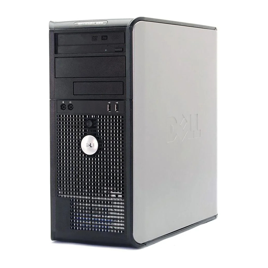
Page 76: About Your Mini Tower Computer
About Your Mini Tower Computer Front View location of Use the Service Tag to identify your computer when you access the Dell Service Tag Support website or call technical support. CD/DVD drive Insert a CD or DVD (if supported) into this drive. - Page 77 different operating states: No light — The computer is turned off. Steady green — The computer is in a normal operating state. Blinking green — The computer is in a power-saving mode. Blinking or solid amber — See Power Problems. To exit from a power-saving mode, press the power button or use the keyboard or the mouse if it is configured as a wake device in the Windows Device Manager.
- Page 78 parallel Connect a parallel device, such as a printer, to the parallel connector. If connector you have a USB printer, plug it into a USB connector. NOTE: The integrated parallel connector is automatically disabled if the computer detects an installed card containing a parallel connector configured to the same address.
- Page 79 CAUTION: To avoid electrical shock, always unplug your computer from the electrical outlet before removing the computer cover. NOTICE: Be careful when opening the computer cover to ensure that you do not accidentally disconnect cables from the system board. floppy drive system board CD/DVD drive...
- Page 80 6 SATA drive connectors (SATA0, SATA1) 15 PCI card connectors (2) 7 power connector (POWER) 16 floppy drive connector (FLOPPY) 8 CD/DVD drive connector (IDE) 17 serial/ PS/2 connector (PS2/SER2) 9 SATA drive connectors (SATA2, SATA3) Back to Contents Page ...
- Page 81 You can do so by touching an unpainted metal surface on the computer chassis. Your Dell™ computer provides the following connectors for PCI and PCI Express cards. Two PCI card slots One PCI Express x16 card slot NOTE: Your Dell computer uses only PCI and PCI Express slots. ISA cards are not supported. Installing a Expansion Card 1. Follow the procedures in Before You Begin.
- Page 82 5. If you are installing a new card, remove the filler bracket to create a card-slot opening. Then continue with step 7 6. If you are replacing a card that is already installed in the computer, remove the card. If necessary, disconnect any cables connected to the card. ...
- Page 83 b. Connect the network cable to the network adapter card's connectors. Do not connect the network cable to the integrated network connector on the back panel of the computer. 16. Install any drivers required for the card as described in the card documentation. Removing an Expansion Card ...
- Page 84 1 card fully seated 2 card not fully seated 3 bracket within slot 4 bracket caught outside of slot 8. Gently press down on the card retention mechanism to secure the adapter bracket in place. 9. Close the card retention latch by snapping it into place. NOTICE: To connect a network cable, first plug the cable into the network wall jack and then plug it into the computer.
- Page 85 Back to Contents Page Processor Dell™ OptiPlex™ 320 User's Guide Removing the Processor Installing the Processor CAUTION: Before you begin any of the procedures in this section, follow the safety instructions located in the Product Information Guide. NOTICE: To prevent static damage to components inside your computer, discharge static electricity from your body before you touch any of your computer's electronic components.
- Page 86 1 center cover latch 2 processor cover 3 processor 4 socket 5 release lever NOTICE: When replacing the processor, do not touch any of the pins inside the socket or allow any objects to fall on the pins in the socket. ...
- Page 87 1 processor cover 6 release lever 2 tab 7 front alignment-notch 3 processor 8 socket and processor pin-1 indicator 4 processor socket 9 rear alignment-notch 5 center cover latch NOTICE: To avoid damage, ensure that the processor aligns properly with the socket, and do not use excessive force when you install the processor. ...
- Page 88 1 heat sink assembly 2 heat-sink assembly bracket 3 captive screw housing (2) 12. Replace the computer cover (see Replacing the Computer Cover). Back to Contents Page ...
- Page 89 Back to Contents Page Dell™ OptiPlex™ 320 User's Guide Drives General Installation Guidelines Hard Drive Drive-Panel Inserts Floppy Drive CD/DVD Drive Your computer supports: Up to two SATA (serial ATA) hard drives One optional floppy drive Up to two CD or DVD drives NOTE: Due to the limited number of drive bays and controllers on this computer, you will not be able to connect all supported devices at once.
- Page 90 1 colored stripe on IDE cable 2 data cable connector 3 system board connector Connect IDE CD/DVD drives to the connector labeled "IDE" on the system board. Connect SATA CD/DVD drives to the connector labeled "SATA2" or "SATA3." SATA hard drives should be connected to the connectors labeled "SATA0" or "SATA1" on the system board. To locate system board connectors, see System Board Components.
- Page 91 Hard Drive CAUTION: Before you begin any of the procedures in this section, follow the safety instructions in the Product Information Guide. CAUTION: To guard against electrical shock, always unplug your computer from the electrical outlet before removing the computer cover. NOTICE: To avoid damage to the drive, do not set it on a hard surface.
- Page 92 1 hard drive 2 release tabs (2) Installing a Hard Drive 1. Unpack the replacement hard drive, and prepare it for installation. 2. Check the documentation for the drive to verify that it is configured for your computer. ...
-
Page 93: Adding A Second Hard Drive
12. Partition and logically format your drive before you proceed to the next step. See the documentation for your operating system for instructions. 13. Test the hard drive by running the Dell Diagnostics (see Dell Diagnostics). 14. If the drive you just installed is the primary drive, install your operating system on the hard drive. - Page 94 5. Move the first hard drive from the upper bay to the lower bay: a. Disconnect the power and the data cables from the back of the first hard drive. b. Press in on the blue release tabs on each side of the drive and slide the first hard drive up and out of the upper bay. c.
-
Page 95: Drive-Panel Inserts
1 hard-drive data cable 2 hard-drive data connector on system board (SATA0 or SATA1) 3 power cable 10. Replace the computer cover (see Replacing the Computer Cover). Drive-Panel Inserts 1. Follow the procedures in Before You Begin. 2. -
Page 96: Removing The Floppy Drive
1 CD/DVD-drive panel insert 2 floppy-drive panel insert 3 holder for shoulder screws 5. Reattach the drive panel to the front of the computer. The drive panel only fits when it is correctly oriented. Floppy Drive CAUTION: Before you begin any of the procedures in this section, follow the safety instructions located in the Product Information Guide. ... -
Page 97: Installing The Floppy Drive
1 floppy drive 2 drive release latch 5. If you are replacing the floppy drive, see Installing the Floppy Drive. Otherwise, replace the drive panel by aligning its hinges and rotating it up until it snaps into place. 6. - Page 98 7. Enter system setup and use the Diskette Drive option to enable your new floppy drive (see Entering System Setup). 8. Verify that your computer works correctly by running the Dell Diagnostics (see Dell Diagnostics). CD/DVD Drive ...
-
Page 99: Removing A Cd/Dvd Drive
Removing a CD/DVD Drive 1. Follow the procedures in Before You Begin. 2. Remove the drive panel by sliding the drive release latch downward to open the panel, and then remove it from the hinges. 3. Disconnect the power and data cables from the back of the drive. ... - Page 100 8. Replace the drive panel by aligning its hinges and rotating it up until it snaps into place. 9. Replace the computer cover (see Replacing the Computer Cover). 10. Verify that your computer works correctly by running the Dell Diagnostics (see Dell Diagnostics). Back to Contents Page ...
- Page 101 Back to Contents Page I/O Panel Dell™ OptiPlex™ 320 User's Guide Removing the I/O Panel CAUTION: Before you begin any of the procedures in this section, follow the safety instructions located in the Product Information Guide. CAUTION: To guard against electrical shock, always unplug your computer from the electrical outlet before removing the cover.
- Page 102 Back to Contents Page Power Supply Dell™ OptiPlex™ 320 User's Guide Replacing the Power Supply DC Power Connectors Replacing the Power Supply CAUTION: Before you begin any of the procedures in this section, follow the safety instructions located in the Product Information Guide.
- Page 103 9. Reconnect the DC power cables to the power supply. 10. Connect the AC power cable to the AC power connector. 11. Replace the computer cover (see Replacing the Computer Cover). DC Power Connectors DC Power Connector P1 ...
- Page 104 Black Black +5 VDC +5 VDC +5 VDC Black *Use 22-AWG wire instead of 18-AWG wire. DC Power Connector P2 Pin Number Signal Name 18-AWG Wire Black Black +12 VDC Yellow +12 VDC Yellow DC Power Connectors P3 and P5 ...
- Page 105 Pin Number Signal Name 22-AWG Wire +5 VDC Black Black +12 VDC Yellow DC Power Connectors P8 and P9 Pin Number Signal name 18-AWG Wire +12 VDC White Black Black +5 VDC Back to Contents Page ...
- Page 106 Back to Contents Page Removing the Computer Cover Dell™ OptiPlex™ 320 User's Guide CAUTION: Before you begin any of the procedures in this section, follow the safety instructions located in the Product Information Guide. CAUTION: To guard against electrical shock, always unplug your computer from the electrical outlet before removing the computer cover.
-
Page 107: Mini Tower Computer Specifications
Back to Contents Page Mini Tower Computer Specifications Dell™ OptiPlex™ 320 User's Guide Microprocessor Microprocessor type Intel® Pentium® or Celeron® processor internal cache up to 2 MB pipelined-burst, eight-way set associative, write-back SRAM Memory Type 533- or 667-MHz DDR2 SDRAM Memory connectors Memory modules supported 256-MB, 512-MB, or 1-GB non-ECC... - Page 108 Cards: full-height cards supported PCI: connectors connector size 120 pins connector data width 32 bits (maximum) PCI Express: connectors one x16 power 25 W maximum connector size 164 pins connector data width (maximum) sixteen PCI Express lane Drives Externally accessible one 3.5-inch drive bay two 5.25-inch drive bays Internally accessible...
- Page 109 Link integrity light (on integrated network adapter) green light for 10-Mb operation and orange light for 100-Mb operation Activity light (on integrated network adapter) yellow blinking light Diagnostic lights four lights on the front panel (see Diagnostic Lights) Standby power light AUX_PWR on the system board ...
-
Page 110: Microsoft® Windows® Xp Features
Back to Contents Page Microsoft® Windows® XP Features Dell™ OptiPlex™ 320 User's Guide Transferring Information to a New Computer User Accounts and Fast User Switching Setting Up a Home and Office Network Transferring Information to a New Computer The Microsoft Windows XP operating system provides a Files and Settings Transfer wizard to move data from the source computer to the new computer. You can move data such as: E-mails... -
Page 111: User Accounts And Fast User Switching
User Accounts and Fast User Switching Adding User Accounts After the Microsoft Windows XP operating system is installed, the administrator or a user with administrator rights can create additional user accounts. 1. Click the Start button and click Control Panel. ... - Page 112 1. Click the Start button, point to All Programs® Accessories® Communications, and then click Network Setup Wizard. 2. On the welcome screen, click Next. 3. Click Checklist for creating a network. NOTE: Selecting the connection method This computer connects directly to the Internet enables the integrated firewall provided with Windows XP SP1.
-
Page 113: Replacing The Computer Cover
Back to Contents Page Replacing the Computer Cover Dell™ OptiPlex™ 320 User's Guide CAUTION: Before you begin any of the procedures in this section, follow the safety instructions in the Product Information Guide. 1. Ensure that all cables are connected, and fold cables out of the way. -
Page 114: Abbreviations And Acronyms
ENERGY STAR guidelines for energy efficiency. Other trademarks and trade names may be used in this document to refer to either the entities claiming the marks and names or their products. Dell Inc. disclaims any proprietary interest in trademarks and trade names other than its own. -
Page 115: Reinstalling Drivers And The Operating System
A driver acts like a translator between the device and any other programs that use the device. Each device has its own set of specialized commands that only its driver recognizes. Dell ships your computer to you with required drivers already installed—no further installation or configuration is needed. NOTICE: The optional Drivers and Utilities CD (Resource CD) may contain drivers for operating systems that are not on your computer. -
Page 116: Using The Optional Drivers And Utilities Cd
If this is your first time to use the Drivers and Utilities CD, the Installation window opens to inform you that the CD will begin the installation. Click OK and respond to the installation program prompts to complete the installation. 2. Click Next at the Welcome Dell System Owner screen. 3. Choose the appropriate selections for System Model, Operating System, Device Type, and Topic. -
Page 117: Restoring The Computer To An Earlier Operating State
Restoring the Computer to an Earlier Operating State NOTICE: Before you restore the computer to an earlier operating state, save and close any open files and exit any open programs. Do not alter, open, or delete any files or programs until the system restoration is complete. ... -
Page 118: Reinstalling Windows Xp
The Operating System CD provides options for reinstalling Windows XP. The options can overwrite files and possibly affect programs installed on your hard drive. Therefore, do not reinstall Windows XP unless a Dell technical support representative instructs you to do so. - Page 119 Next. 9. If the Modem Dialing Information screen appears, enter the requested information and click Next. 10. Enter the date, time, and time zone in the Date and Time Settings window, and click Next. 11. If the Networking Settings screen appears, click Typical and click Next. ...
-
Page 120: Solving Problems
If you have to repeatedly reset time and date information after turning on the computer, or if an incorrect time or date displays during start-up, replace the battery (see Battery). If the battery still does not work properly, contact Dell (see Contacting Dell). -
Page 121: Keyboard Problems
Running the Dell IDE Hard Drive Diagnostics — The Dell IDE Hard Drive Diagnostics is a utility that tests the hard drive to troubleshoot or confirm a hard drive failure. 1. Turn on your computer (if your computer is already on, restart it). -
Page 122: The Computer Does Not Start Up
If you installed a unique image on your computer or if you had to reinstall your operating system, run the DSS utility. DSS is available on your Drivers and Utilities CD (see Finding Information) and at support.dell.com. ® ® NOTE:... -
Page 123: Memory Problems
Save and close any open files and exit any open programs you are not using to see if that resolves the problem. See the software documentation for minimum memory requirements. If necessary, install additional memory (see Memory). Reseat the memory modules to ensure that your computer is successfully communicating with the memory (see Memory). Run the Dell Diagnostics (see Dell Diagnostics). -
Page 124: Network Problems
1. Enter system setup and ensure that the Mouse Port option is set to On (see System Setup). 2. Exit system setup and restart the computer. Reinstall the mouse driver — See Drivers. Run the Dell Diagnostics — See Dell Diagnostics. Check for software and hardware conflicts — See Resolving Software and Hardware Incompatibilities. -
Page 125: Printer Problems
properly. Ensure that the electrical outlet is working by testing it with another device, such as a lamp. Ensure that the main power cable and front panel cable are securely connected to the system board. If the power light is amber and green or steady amber — A device might be malfunctioning or incorrectly installed. Remove and then reinstall the memory modules (see Memory). -
Page 126: Serial Or Parallel Device Problems
See the device's documentation for the recommended settings. Then enter system setup and ensure that the Serial Port #1 setting or the LPT Port Mode setting matches the recommended settings (see System Setup). Run the Dell Diagnostics — See Dell Diagnostics. Sound and Speaker Problems... -
Page 127: No Sound From Headphones
See Drivers. Check the device option setting — Enter system setup (see System Setup) and ensure that the Audio Controller option is set to On. Exit system setup and restart your computer. Run the Dell Diagnostics — See Dell Diagnostics. Check for software and hardware conflicts — See Resolving Software and Hardware Incompatibilities. -
Page 128: If The Screen Is Difficult To Read
Test the monitor — Connect a properly working monitor to the computer, and try using the monitor. If the new monitor works, the original monitor is faulty. Check the diagnostic lights — See Diagnostic Lights. Check the card setting — Enter system setup and ensure that Primary Video option is set correctly. Exit system setup and restart your computer (see System Setup). -
Page 129: Removing The System Board
Back to Contents Page System Board Dell™ OptiPlex™ 320 User's Guide Replacing the System Board Removing the System Board 1. Follow the procedures in Before You Begin. CAUTION: To guard against the electrical shock, always unplug your computer from the electrical outlet before removing the cover. - Page 130 3. Replace any components and cables that you removed from the system board. 4. Reconnect all cables to their connectors at the back of the computer. 5. Replace the computer cover (see Replacing the Computer Cover). Back to Contents Page ...
- Page 131 Zone, and PowerApp are trademarks of Dell Inc.; Intel, Pentium, SpeedStep, and Celeron are registered trademarks of Intel Corporation; Microsoft and Windows are registered trademarks of Microsoft Corporation; Bluetooth is a trademark owned by Bluetooth SIG, Inc. and is used by Dell Inc. under license. ENERGY STAR is a registered trademark of the U.S.
-
Page 132: Troubleshooting Tools And Utilities
Before you begin any of the procedures in this section, follow the safety instructions located in the Product Information Guide. When to Use the Dell Diagnostics If you experience a problem with your computer, perform the checks in this section and run the Dell Diagnostics before you contact Dell for technical assistance (see Dell Diagnostics). -
Page 133: System Lights
NOTE: The Service Tag for your computer is located at the top of each test screen. If you contact Dell, technical support will ask for your Service Tag. Your computer's Service Tag is listed in the System Info option in system setup (see System Setup). -
Page 134: Diagnostic Lights
If the problem still exists, install a graphics card that you know works and restart the computer. If the problem persists or the computer has integrated graphics, contact Dell (see Contacting Dell). A possible floppy or hard drive failure has Reseat all power and data cables and restart the computer. -
Page 135: Beep Codes
If your computer beeps during start-up: 1. Write down the beep code on the Diagnostics Checklist. 2. Run the Dell Diagnostics to identify a more serious cause (see Dell Diagnostics). 3. Contact Dell for technical assistance (see Contacting Dell). -
Page 136: Error Messages
4. See the program documentation for installation instructions. Alert! Previous attempts at booting this system have failed at checkpoint [nnnn]. For help in resolving this problem, please note this checkpoint and contact Dell Technical Support — Contact Dell and report the checkpoint code (nnnn) to the support technician (see Contacting Dell). ... - Page 137 Enter system setup and ensure that the computer configuration information for the hard drive is correct (see System Setup). No timer tick interrupt — Run the Dell Diagnostics. See Dell Diagnostics. Non-system disk or disk error — Replace the floppy disk with one that has a bootable operating system or remove the floppy disk from drive A and restart the computer.
- Page 138 WARNING: Dell's Disk Monitoring System has detected that drive [0/1] on the [primary/secondary] EIDE controller is operating outside of normal specifications. It is advisable to immediately back up your data and replace your hard drive by calling your support desk or Dell —...
-
Page 139: Resolving Software And Hardware Incompatibilities
Resolving Software and Hardware Incompatibilities If a device is either not detected during the operating system setup or is detected but incorrectly configured, you can use Device Manager or the Hardware Troubleshooter to resolve the incompatibility. ® ® Microsoft Windows To resolve incompatibilities using Device Manager: ... -
Page 140: Warranty
Dell™ OptiPlex™ 320 User's Guide Dell Inc. ("Dell") manufactures its hardware products from parts and components that are new or equivalent to new in accordance with industry-standard practices. For information about the Dell warranty for your computer, see the Product Information Guide or separate paper warranty document that shipped with your computer.
Need help?
Do you have a question about the OptiPlex 320 and is the answer not in the manual?
Questions and answers