Sony HDC1500 Series Operation Manual
Hd color camera
Hide thumbs
Also See for HDC1500 Series:
- Operation manual (62 pages) ,
- Maintenance manual (550 pages) ,
- Maintenance manual (144 pages)

Related Manuals for Sony HDC1500 Series


Summary of Contents for Sony HDC1500 Series
- Page 1 * 3 - 8 6 8 - 7 4 9 - 0 9 * HD COLOR CAMERA HDC1500 Series OPERATION MANUAL [Japanese/English] 1st Edition (Revised 8)
- Page 2 English For the State of California, USA only WARNING Perchlorate Material - special handling may apply, See To reduce the risk of fire or electric shock, www.dtsc.ca.gov/hazardouswaste/perchlorate Perchlorate Material : Lithium battery contains perchlorate. do not expose this apparatus to rain or moisture.
- Page 3 électromagnétiques suivants : E1 (résidentiel), E2 (commercial et industrie légère), E3 (urbain extérieur) et E4 (environnement EMC contrôlé, ex. studio de télévision). Le fabricant de ce produit est Sony Corporation, 1-7-1 Konan, Minato-ku, Tokyo, Japon. Le représentant autorisé pour EMC et la sécurité des produits est Sony Deutschland GmbH, Hedelfinger Strasse 61, 70327 Stuttgart, Allemagne.
-
Page 4: Table Of Contents
Table of Contents Overview................60 Features..................60 System Configuration ..............62 Precautions ................66 Phenomena Specific to CCD Image Sensors......66 Locations and Functions of Parts........67 Accessory Attachments..............67 Controls and Connectors............68 Preparations................76 Attaching a Lens ................76 Adjusting the Flange Focal Length..........76 Attaching a Viewfinder..............76 Adjusting the Shoulder Pad Position .........78 Mounting the Camera to a Tripod..........79 Adjustments and Settings for Recording......80 Adjusting the Black Balance and White Balance ......80... -
Page 5: Overview
Overview The HDC1500-series cameras, HDC1500, HDC1550, quality and higher stability in image creation while HDC1400, and HDC1450, are 2/3-type high-definition maintaining conventional popular functions and portable video cameras equipped with CCD for 2,200,000 operability. pixels. They incorporate the latest pickup elements and digital signal-processing LSI to yield higher picture The differences among the models are shown below: HDC1500... - Page 6 Memory Sticks. menus displayed on the viewfinder screen or an external monitor. 1) Memory Stick and are trademarks of Sony Corporation. 2) Safety zone marker: A box-shaped marker displayed on the viewfinder screen which indicates Various color-reproduction functions 80%, 90%, 92.5%, or 95% of the total screen area...
-
Page 7: System Configuration
Note Production of some of the peripherals and related devices shown in the figures has been discontinued. For device about choosing devices, please contact your Sony dealer or a Sony sales representative. Overview... - Page 8 Connection example 1 (HDC1500/1400) HDVF-C730W/C950W HKCU1001 Viewfinder HDVF-20A HKCU1003 BKW-401 Viewfinder HDVF-C35W Rotation Bracket Viewfinder HKCU1005 Zoom Lens HDC1500/1400 (for ENG/EFP) Optical Fiber Cable HDCU1000 HD Camera With HKCU1001 CAC-6 Control Unit or HKCU1003 Return Video Selector Memory Stick Intercom Headset Picture Waveform VCT-14...
- Page 9 Connection example 2 (HDC1550/1450) HDVF-C730W/C950W Viewfinder HKCU1001 HDVF-20A BKW-401 Viewfinder HDVF-C35W HKCU1003 Rotation Bracket Viewfinder HDFX100 HKCU1005 Zoom Lens HD Triax HDC1550/1450 (for ENG/EFP) CCU Adaptor Triax Cable With HKCU1001 HDCU1000 HD Camera or HKCU1003 Control Unit Memory Stick Optical Fiber VCT-14 CAC-6 Picture...
-
Page 10: Connection Example
Connection example 3 HDC-950 or HDC1500/1400 HD Color Video Camera +Large Lens Adaptor HDC-950 or HDC1500/1400 HD Color Video Camera HDC1550/1450 HD Color Video Camera +Large Lens Adaptor +HDVF-C730W/C950W Electronic Viewfinder RCP-700/900-series Remote Control Panel HDC1550/1450 HD Color Video Camera Maximum cable run with Triax cable Notes The maximum Triax cable length between the HDC1550/... -
Page 11: Precautions
• when operating at a high environmental temperature Precautions • when you have raised the master gain (sensitivity) This product has a compensation function and the problem may be alleviated by automatic black balance adjustment (see page 80). Note on laser beams Laser beams may damage the CCDs. -
Page 12: Locations And Functions Of Parts
Locations and Functions of Parts Accessory Attachments a VF connector b Shoulder strap fitting post c Viewfinder front-rear positioning lever and lock knob d Viewfinder left-right positioning ring e Lens cable clamp f Lens fixing lever g Lens mount cap h Lens mount i LENS connector k Shoulder pad... -
Page 13: Controls And Connectors
j Tripod mount k Shoulder pad Attach the VCT-14 Tripod Adaptor when mounting the You can adjust the position so that you can get the best camera on a tripod. balance for shooting with the camera on your shoulder. For details, see “Adjusting the Shoulder Pad Position” on page 78. - Page 14 A or B: Selects memory A or B. Pressing the left button selects the available ND filters (clear, 1/4ND, 1/8ND, 1/16ND,1/64ND) in sequence. j DISPLAY switch Pressing the right button selects the available CC filters (cross, 3200K, 4300K, 6300K, 8000K) in sequence. The functions of the DISPLAY switch are as follows: ON: Characters and messages showing the camera settings HDC1400/1450...
- Page 15 Front left d SHUTTER switch a RET 1 button e INTERCOM LEVEL control b MIC 1 IN connector c MIC power switch f RET 2 button a RET 1 (return video 1) button OFF: The electronic shutter does not function. The return video 1 signal from the camera control unit is ON: The electronic shutter is activated.
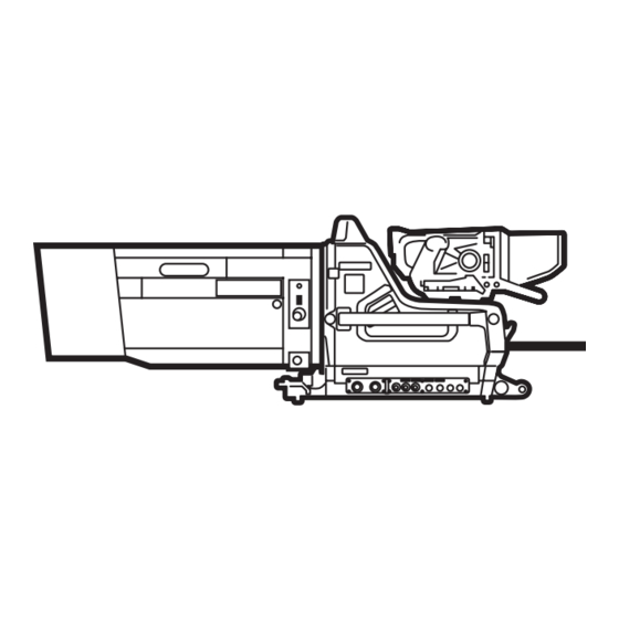
- Page 16 Rear The figure shows HDC1500. b Tally lamp and switch Shoulder strap fitting post (page 67) Operation panel (page 72, page 73) c CCU connector (HDC1500/1400) HDCU/HDFX connector (HDC1550/ 1450) d SDI 1 connector (HDC1500 only) e PROMPTER2 connector (HDC1500 only) f Connector panel (page 74) a CAMERA POWER switch g CALL button...
- Page 17 Operation panel SY type: For UC/SYL/JN3 (USA, Canada, and other countries) and JN4 (East Asia) models (for NTSC areas) For details on the differences among models, see “Overview” on page 60. b RET 1 button and select switch a INTERCOM1 and INTERCOM2 controls and switches c RET 2 button and select switch d LIGHT switch PGM1 control...
- Page 18 European type: For CE (Europe) and E33 (China and South Asia) models (for PAL areas) For details on the differences among models, see “Overview” on page 60. b RET 1 button and select switch a INTERCOM1 and INTERCOM2 controls and switches c RET 2 button and select switch ENG control d LIGHT switch...
- Page 19 Connector panel The figure shows HDC1500. g INTERCOM1 and 2 connectors a EARPHONE jack RET CTRL EARPHONE REMOTE b RET CTRL connector h REMOTE connector c CRANE connector RET IN TRACKER CRANE GENLOCK IN i GENLOCK IN/RET IN/PROMPTER d TRACKER connector connector and switch (HDC1500/1550) PROMPTER PROMPTER connector (HDC1400/1450)
- Page 20 connected, the signal of input 1 is output from this MIC: When an external microphone is connected connector. CH2 audio input select switch i PROMPTER (prompter signal output) connector Set to the appropriate position according to the equipment connected to the AUDIO IN CH2 connector. (BNC type) (HDC1400/1450) LINE: When a line-level (0 dBu) signal source is Used for output of a prompter signal (valid only when a...
-
Page 21: Preparations
Note Preparations The various parts of the lens used in adjusting the flange focal length are in different positions on different lenses. Refer to the lens’ operation manual. Attaching a Lens The procedure for adjusting the flange focal length is as follows: The procedure for attaching a lens to the camera is as follows:... - Page 22 Example: Attaching a HDVF-20A/C35W To adjust the position to the left or right Viewfinder For details on the viewfinder, refer to the instruction Viewfinder left-right positioning ring manual of the viewfinder. Attaching procedure Slide the viewfinder in the direction of the arrow. The viewfinder stopper automatically pops down.
-
Page 23: Adjusting The Shoulder Pad Position
Keeping the viewfinder from hitting your To keep the viewfinder from bumping your leg when carrying the camera, install the BKW-401 Viewfinder Rotation Bracket (optional) and rotate the viewfinder upwards. In the same manner as step 1, remove the viewfinder shoe of the camera from the front-rear positioning mechanism. -
Page 24: Mounting The Camera To A Tripod
Tripod adaptor Shoulder pad lock lever Tripod Bottom of the camera Shoulder pad Place the camera on the tripod adaptor, and slide forward it along the groove of the tripod adaptor until it clicks. Adjusting procedure Raise the lever in the center of the shoulder pad to unlock the shoulder pad. -
Page 25: Adjustments And Settings For Recording
If the pin of the tripod adaptor does not return to Adjustments and its original position After removing the camera, if the pin of the tripod adaptor Settings for Recording does not return to its original position, hold down the red button and move the lever in the direction of the arrow to return the pin to its original position. -
Page 26: Adjusting The White Balance
Adjusting the white balance Automatic adjustment of white balance is performed with the following procedure: Procedure for adjusting the white balance Set the WHITE BAL switch to A or B. AUTO W/B BAL switch The switch will return to the center position, and adjustment will be performed. - Page 27 ND Filter Color temperature conversion filter A rectangle centered in the screen. The length of clear cross filter the sides must be at least 70% of the height and 1/4 ND 3200K (clear) width of the screen. 1/8 ND 4300K 1/16 ND 6300K 1/64 ND...
-
Page 28: Setting The Electronic Shutter
is controlled from the external control device and control on the camera are disabled. About the shutter modes The shutter modes that can be used with the electronic AWB:OK shutter of the camera and the shutter speeds that may be selected are as follows: Shutter modes and speeds Shutter... -
Page 29: Setting The Camera Outputs
The current shutter setting will be displayed in the Setting the Camera setting change/adjustment progress message display area of the viewfinder screen for about three seconds. Outputs Example: “Shutter: 1/250” Push the SHUTTER switch to the SEL position again You can specify video signals directly output from the before the display disappears. - Page 30 Outputting the same image as that on the Menu page Item Setting viewfinder <DOWN CONVERTER> OUTPUT SIGNAL MAIN • With HD SDI, you can obtain a signal that includes the <SDI-2 OUT> (HDC1500) OUTPUT SD-SDI <SDI OUT> (HDC1550/ same information as that being displayed on the 1400/1450) viewfinder according to the settings of the VF MARKER, CHARACTER,VF DETAIL, ZEBRA, etc.
- Page 31 Note This function cannot be used when a camera control unit is connected. To output in 1080/59.94P or 1080/50P Menu page Item Setting <OUTPUT FORMAT> ACTIVE LINE 1080 (Format) 59.94P or 50P <POWER SAVE> SDI-2 OUT ACTIVE <SDI-2 OUT> OUTPUT LINK-B Setting the Camera Outputs...
-
Page 32: Viewfinder Screen Status Display
Viewfinder Screen Status Display Besides the video image, the viewfinder can display text status, as well as items such as a center marker or safety and messages showing the camera settings and operation zone marker. When the DISPLAY switch is set to ON Items set to ON using the menu or related switches will be displayed on the upper and lower edges of the screen. -
Page 33: Menu Operations
When you press the CANCEL/STATUS Menu Operations switch toward STATUS The status display is changed to show the following items: The menus displayed on the viewfinder enable various settings of the camera. a Assignable switch indication The following controls are used to operate the menus. b Format indication FORMAT :1080-59.94i... -
Page 34: Selecting Pages
Available menus The CONTENTS page or the last operated page of the selected menu is displayed. USER menu This menu can include menu pages selected from among Selecting Pages the OPERATION, PAINT, MAINTENANCE, FILE, and DIAGNOSIS menus, for convenience. Changing, adding, and deleting pages can be performed with the USER When selecting a page from a CONTENTS MENU CUSTOMIZE menu. -
Page 35: Setting The Menu Items
Rotate the MENU SEL knob/ENTER button to flip Push on the MENU SEL knob/ENTER button. through the pages. The “?” mark will change back to the arrow marker ), and the new setting will be registered. When the desired page is displayed, push on the MENU SEL knob/ENTER button. - Page 36 The following pages are included on the factory-set USER Turn the MENU SEL knob/ENTER button to move the menu: arrow marker ( ) to “USER MENU CUSTOMIZE”, then push on the MENU SEL knob/ENTER button. Menu page title USER Source menu / page No. If this is the first time the USER MENU CUSTOMIZE menu menu has been displayed, the CONTENTS page of the...
- Page 37 Turn the MENU SEL knob/ENTER button to move the <SW STATUS> arrow marker ( ) to the position where you wish to FLARE move the item, then push on the MENU SEL knob/ GAMMA BLK GAM : OFF ENTER button. KNEE WHT CLIP: DETAIL...
- Page 38 If a different page is displayed, turn the MENU SEL the page to be deleted, and push on the MENU SEL knob/ENTER button until the EDIT PAGE screen knob/ENTER button. appears, then push on the MENU SEL knob/ENTER The EDIT FUNCTION screen appears. button to select the page.
-
Page 39: Menu List
Menu List This section shows the menus to be displayed on the Notes viewfinder in tables. HDLA: HDLA1500-series Large Lens Adaptor • For the pages that have been registered in the USER CCU: HDCU1000/1500 Camera Control Unit menu at the factory, the USER menu page numbers are Execute by ENTER: Execute by pushing on the MENU indicated in parenthesis in the No. - Page 40 Page title Item Default Settings Remarks <'!' IND> [IND] ON ON, OFF [IND]: Set whether to be (U04) included in the status [NORMAL] 1 – – – – 1, 2, 3, 4, 5 (combination indications on the allowed) viewfinder (see page 88). [IND] ON ON, OFF [NORMAL]: Specify the...
- Page 41 Page title Item Default Settings Remarks <ZEBRA> ZEBRA ON, OFF (U07) 1, 2, 1&2 ZEBRA1 LEVEL 50 to 109% WIDTH 0 to 30% ZEBRA2 100% 50 to 109% <CURSOR> CURSOR ON, OFF display only if HDLA attached (U06) BOX/CROSS BOX, CROSS H POSITION 0 to 99 display only if HDLA attached...
- Page 42 Page title Item Default Settings Remarks <SWITCH ASSIGN2> LENS VTR S/S RETURN2 SW OFF, RETURN1 SW, Assign a function to the VTR (U09) RETURN2 SW, INCOM1, START/STOP switch on the INCOM2 mounted lens. FRONT RET1 RETURN1 SW OFF, RETURN1 SW, D.EXTENDER cannot be RETURN2 SW, INCOM1, selected on HDC1400/1450.
- Page 43 Page title Item Default Settings Remarks <RECEIVE SEL1> INTERCOM1 SEPARATE SEPARATE, MIX RECEIVE SEL INTERCOM LEFT RIGHT, LEFT, BOTH, - - - UC/SYL/JN3/JN4 models only LEFT RIGHT, LEFT, BOTH, - - - CE/E33 models only PROD LEFT RIGHT, LEFT, BOTH, - - - CE/E33 models only PGM1 RIGHT...
-
Page 44: Paint Menu
Page title Item Default Settings Remarks <LENS FILE> FILE 1 to 16 (U11) xxxx... Lens file name display only F.xx F-stop number of the lens display only CENTER MARKER To set and store the center marker position: H POS –20 to +20 H POS: Increasing the value V POS –20 to +20... - Page 45 Menu page Item⁄ Default Settings Remarks <BLACK GAMMA> [R] [G] [B] [M] R, G, B, and M (master) values LEVEL –99 to +99 can be independently set. RANGE HIGH LOW, L.MID, H.MID, HIGH ON, OFF TEST OFF, SAW, 3 STEP, 10 STEP <SATURATION>...
- Page 46 Menu page Item⁄ Default Settings Remarks <DETAIL 2> H/V RATIO –99 to +99 Absolute value is displayed in ABS mode. FREQ –99 to +99 Absolute value is displayed in ABS mode. MIX RATIO –99 to +99 Absolute value is displayed in ABS mode.
- Page 47 Menu page Item⁄ Default Settings Remarks <SHUTTER> SHUTTER ON, OFF 1/100 (sec) 59.94i: 1/100, 1/125, 1/250, Step shutter setting 1/500, 1/1000, 1/2000 Note 50i: 1/60, 1/125, 1/250, There are some formats that 1/500, 1/1000, 1/2000 cannot be selected on HDC1400/ 29.97PsF: 1/40, 1/60, 1/120, 1450.
-
Page 48: Maintenance Menu
MAINTENANCE Menu Menu page Item⁄ Default Settings Remarks <AUTO SETUP> AUTO BLACK Execute by ENTER. AUTO WHITE Execute by ENTER. AUTO LEVEL Execute by ENTER. AUTO WHITE SHADING Execute by ENTER. AUTO BLACK SHADING Execute by ENTER. TEST OFF, SAW, 3STEP, 10STEP <WHITE SHADING>... - Page 49 Menu page Item⁄ Default Settings Remarks <AUTO IRIS> AUTO IRIS ON, OFF WINDOW 1, 2, 3, 4, 5, 6 Select the auto iris windows: The shaded parts indicate the area where light detection occurs. OVERRIDE –99 to +99, - - To set the override to temporarily change the reference value for brightness...
- Page 50 Menu page Item⁄ Default Settings Remarks <OUTPUT FORMAT> CURRENT 1080-50i (V) Displays the current format. (HDC1400 CE/E33 (U15) ACTIVE LINE 1080 1080, 720 The selectable frame setting is and HDC1450 CE displayed for the selected 1080: 50i models) ACTIVE LINE (not displayed 720: 50P with CCU connected) <DOWN...
-
Page 51: File Menu
Menu page Item⁄ Default Settings Remarks <OTHERS 2> DATE TYPE 5 M/D/Y 1 Y/Mn/D Y: Year 2 Mn/D Mn: Month (numeric) 3 D/M/Y M: Month (character string) 4 D/M D: Day 5 M/D/Y 6 M/D WHITE MEMORY ON, OFF Set to ON to use independent white memory at each CC filter position (HDC1500/1550 only). - Page 52 Menu page Item⁄ Default Settings Remarks <SCENE FILE> To store and read scene files (paint data): When storing a file in camera memory, specify the number before executing STORE. When reading, only specify the number. STORE Execute by ENTER. STANDARD Execute by ENTER.
-
Page 53: Diagnosis Menu
Menu page Item⁄ Default Settings Remarks <FILE CLEAR> PRESET OPERATOR Execute by ENTER. REFERENCE (ALL) Execute by ENTER. 10 SEC CLEAR ON, OFF OFF: To exclude the 10 SEC setting when executing REFERENCE (ALL) LENS (CURRENT) Execute by ENTER. To return the settings of the currently selected lens file to the factory-set conditions. -
Page 54: Using A "Memory Stick
MagicGate copyright protection technology cannot be Using a “Memory Stick” written to “Memory Stick-R.” “Memory Stick” Stores any type of data except copyright-protected data When a “Memory Stick” is inserted in the camera, the file that requires the MagicGate copyright protection data can be stored on the “Memory Stick,”... - Page 55 Precautions • To prevent data loss, make backups of data frequently. In no event will Sony be liable for any loss of data. • Unauthorized recording may be contrary to the provisions of copyright law. When you use a “Memory Stick”...
-
Page 56: Specifications
Specifications Optical system specifications HDC1500 Spectral system F1.4 prism Built-in filters Color temperature conversion filters General A: cross filter B: 3200K (clear) Power requirements 240 V AC, 1.4 A (max.) C: 4300K 180 V DC, 1.0 A (max.) D: 6300K 12 V DC, 7 A (max.) E: 8000K Operating temperature... -
Page 57: Hdc1550
DC OUT 4-pin (1), 10.5 to 17 V DC, 1.5 A Pour les utilisateurs aux Etats-Unis, au Canada, en Europe, à l’Australie, et à la Nouvelle-Zélande maximum Connecteurs pour les câbles optiques/électriques It may be limited depending on the composites: load and input conditions. - Page 58 Typical −54 dB/−62 dB (NS MAX) Image S/N INTERCOM1, INTERCOM2 Horizontal resolution XLR 5-pin, female (1 each) 1000 TV lines (at center of screen) EARPHONE Stereo minijack (1) 5% or higher modulation DC IN XLR 4-pin (1), 10.5 to 17 V DC Registration 0.02% for total area (not including lens distortion)
-
Page 59: Hdc1400
Related equipment Horizontal resolution 1000 TV lines (at center of screen) HDFX100 HD Triax CCU Adaptor 5% or higher modulation HDCU1000/1500 HD Camera Control Unit Registration 0.02% for total area (not including MSU-900/950 Master Setup Unit lens distortion) RCP-700/900-series Remote Control Panel Geometric distortion Negligible (not including lens VCS-700 Video Selector distortion) -
Page 60: Hdc1450
BNC type (1) • LEMO FUW.3K.93C.TLMC96 (au connecteur ® TEST OUT BNC type (1) « HDCU » de la caméra) PROMPTER BNC type (1), 1 Vp-p, 75 ohms Précaution concernant le câble optique/électrique RET CTRL 6-pin (1) composite: REMOTE 8-pin (1) Pour la connexion entre l’unité... - Page 61 Registration 0.02% for total area (not including RET CTRL 6-pin (1) lens distortion) REMOTE 8-pin (1) Geometric distortion Negligible (not including lens TRACKER 10-pin (1) distortion) CRANE 12-pin (1) Optical system specifications Supplied accessories Spectral system F1.4 prism Operation manual (1) Built-in optical filters1: clear Switch label 1, 2 (1 each) 2: 1/4 ND...
- Page 62 Note Always verify that the unit is operating properly before use. SONY WILL NOT BE LIABLE FOR DAMAGES OF ANY KIND INCLUDING, BUT NOT LIMITED TO, COMPENSATION OR REIMBURSEMENT ON ACCOUNT OF THE LOSS OF PRESENT OR PROSPECTIVE PROFITS DUE TO FAILURE OF...
- Page 63 Specifications...
- Page 64 The material contained in this manual consists of information that is the property of Sony Corporation and is intended solely for use by the purchasers of the equipment described in this manual. Sony Corporation expressly prohibits the duplication of any portion of this manual or the use thereof for any...
- Page 65 * 3 - 8 6 8 - 7 4 9 - 0 9 * Sony Corporation HDC1400 (JN3/JN4/CE/E33) HDC1450 (UC/CE) HDC1500 (SYL/JN4/CE/E33) Printed in Japan HDC1550 (UC/CE) 2008.05.13 HDC1600 (J) © 2005 3-868-749-09(1)
Need help?
Do you have a question about the HDC1500 Series and is the answer not in the manual?
Questions and answers