Table of Contents
Advertisement
CONSUMER ELECTRIC PUMPS
INSTALLATION/OPERATION/PARTS
In addition to installation information, this manual contains warnings, safeguards
and procedures on the use and care of the Series 70 and 1800 pumps. Please leave
this manual with the pump owner after the installation is complete.
The information in this document is confidential and proprietary. No further disclosure shall be made without
permission from Gasboy International, Inc. Gasboy International, Inc. believes that the information in this document
is accurate and reliable. However, we assume no responsibility for its use, nor for any infringements of patents or
other rights of third parties resulting from its use. We reserve the right to make changes at any time without notice.
GASBOY INTERNATIONAL, INC. A TOKHEIM SUBSIDIARY LANSDALE, PA
SERIES 70 AND 1800
MANUAL
INSTALLERS - IMPORTANT
Copyright 1999 by Gasboy International, Inc. All rights reserved.
035219
REV. 0259
Advertisement
Table of Contents
Troubleshooting

Related Manuals for Gasboy 1800 Series


Summary of Contents for Gasboy 1800 Series
- Page 1 SERIES 70 AND 1800 CONSUMER ELECTRIC PUMPS INSTALLATION/OPERATION/PARTS In addition to installation information, this manual contains warnings, safeguards and procedures on the use and care of the Series 70 and 1800 pumps. Please leave this manual with the pump owner after the installation is complete. Copyright 1999 by Gasboy International, Inc.
-
Page 2: Important Warnings And Safeguards
IMPORTANT WARNINGS AND SAFEGUARDS Gasoline and petroleum products are flammable. To avoid injury or death to persons or damage to equipment or property, follow these listed warnings and other warnings and precautions outlined in this manual when installing, using, or working around this equipment. Check with GASBOY Technical Services for compatibility of liquids with pump materials. -
Page 3: Table Of Contents
CONTENTS IMPORTANT WARNINGS AND SAFEGUARDS FOR CONSUMER PUMPS Section 1: INTRODUCTION Purpose... Specifications* ... Section 2: INSTALLATION Installation Precautions... Supply Line - Underground Tanks ... Pump Dimensions - Series 70, Model 1820 ... Pump Dimensions - Series 1820R... Installation Instructions ... Cabinet Removal for Installation or Service (Series 1820 only - Rounded Cabinet)... - Page 4 GASBOY Series 70 & 1800 Troubleshooting ... Disassembly of Pump ... Meter-Register Disassembly... 1860 3-Wheel Register Service and Maintenance ... 4860 4-Wheel Register Service ... Section 6: PARTS Series 70 Assembly ... Optional Accessories... Series 1800 Assembly ... Optional Accessories... Direct Drive Motor-Pump Assembly...
-
Page 5: Introduction
Section 1 INTRODUCTION PURPOSE The GASBOY Series 70 and 1820 Consumer Electric Pumps Installation/Operation Manual is provided to assist the installer in installing and operating the unit. Faulty installations are the major cause of unit malfunctions. This manual should be supplied to the electrician prior to the installation of conduit and wiring. - Page 6 GASBOY Series 70 & 1820 Table 1-1. Series 70 and 1820 Features Stripped-down versions of Series 70 pumps, which mount on customer-supplied piping and fittings, are available. Model 72X has no attachments or register, Model 73 has a hose and nozzle, but no meter or register.
-
Page 7: Section 2: Installation Installation Precautions
Section 2 INSTALLATION INSTALLATION PRECAUTIONS All tanks and installations must conform with all building/fire codes, all Federal, State, and Local codes, National Electrical Code, (NFPA 70), NFPA 30, Automotive and Marine Service Station Code (NFPA 30A) and NFPA 395 codes and regulations. Plan your installation carefully. -
Page 8: Supply Line - Underground Tanks
GASBOY Series 70 & 1820 15. DO NOT use gaskets on covers of explosion-proof type boxes. The sealing compound found around wires at all junction box entrances is a requirement of the National Electrical Code and should not be disturbed. Tighten junction box covers before replacing panels. 16. -
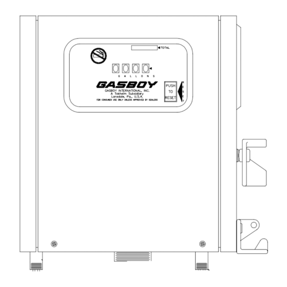
Page 9: Pump Dimensions - Series 70, Model 1820
Installation PUMP DIMENSIONS - SERIES 70, MODEL 1820 Pump diagrams shown are for Model 1820. Pump dimensions are the same for all Series 70 pumps. PUMP DIMENSIONS - MODEL 1820R Pump diagrams shown are for Model 1820R. Pump dimensions are the same for these Model 1820 pumps: 1820R, 1820RSS, 1820RC, 1820RCSS. -
Page 10: Installation Instructions
GASBOY Series 70 & 1820 INSTALLATION INSTRUCTIONS Cabinet Removal for Installation or Service (Series 1820 Only) - Rounded Cabinet Remove two screws, one on each side of the cabinet. Pull front panel assembly forward at bottom. As it clears the pumping unit, lift up to remove. To replace front panel, engage pins at top in matching holes in rear panel. -
Page 11: Direct Mount On Underground Tank
Direct Mount on Underground Tanks Screw 2" coupling onto 2" standard pipe. Screw 2" standard pipe into 2" tank flange. Apply compound to threads at bottom of base to prevent surface water from entering the tank. Screw 1" suction pipe into install-a-socket. Suction pipe should be long enough to allow 3" clearance from bottom of tank. -
Page 12: Direct Mount On Aboveground Tank
GASBOY Series 70 & 1820 Direct Mount on Aboveground Tank Aboveground tanks require both a pressure/vacuum vent and an emergency vent. pressure/vacuum vent reduces losses due to evaporation and is an air quality control measure. The emergency vent provides a relief from the pressure resulting from heating and boiling of the tank contents during a fire situation. -
Page 13: Pedestal Mount Pump
Pedestal Mount Pump Screw 2" coupling onto threaded end of 2" standard pipe. Slide cast iron pedestal base up over the unthreaded end of 2" standard pipe. Screw 1" suction pipe into install-a-socket. Suction pipe should be long enough to allow 3" clearance from bottom of tank. -
Page 14: Wall Mount
GASBOY Series 70 & 1820 Wall Mount The optional wall mount kit can be used with any Series 70 or 1820 pump to be located remote from the tank. The wall mount kit consists of a wall mounting bracket, pump mounting flange, and hardware to attach the flange to the bracket. -
Page 15: Vacuum Breaker
Vacuum Breaker The vacuum breaker tubing kit can be used with any Series 70 or 1820 pump. The vacuum breaker is used to break a siphon should the nozzle drop below the fluid level in the tank while the pump is stuck in the open position. A threaded vacuum breaker, P/N 066570 is shipped installed in the pump. - Page 16 GASBOY Series 70 & 1820 NOTE: Tubing can be piped to any available opening on top of tank. Use reducer bushings as required. Testing the Vacuum Breaker Charge tubing completely with fluid. Turn on pump and run for several minutes to purge any air from the system. Turn off pump.
-
Page 17: Section 3: Wiring Wiring Precautions
Section 3 WIRING WIRING PRECAUTIONS The quality of the electrical installation is a major factor in maintaining proper safety levels and providing trouble-free operation of your GASBOY pump. To assure a quality installation, follow these rules: Have the pump installed by a competent installer/electrician. All wiring must be installed to conform with all building/fire codes, all Federal, State, and Local codes, National Electrical Code, (NFPA 70), NFPA 30, Automotive and Marine Service Station Code (NFPA 30A), and NFPA 395 codes and regulations. -
Page 18: Grounding
GASBOY Series 70 & 1820 GROUNDING To ensure proper operation of the equipment and provide the necessary safety factors, this unit must be grounded. A ground wire (preferably green) must be connected between the unit's AC junction box ground lug and the main electrical service panel. One (1) earth ground connection is required per unit. -
Page 19: Pulser Wiring
Wiring PULSER WIRING An optional pulser (available on the Series 1820R only) is used when external monitoring of the dispensing unit operation is desired. The pulser transmits one electrical signal (pulse) for each predetermined amount of fuel dispensed. Reed 10:1 pulsers operating with DC voltages are used. -
Page 20: Pump Wiring Diagrams
GASBOY Series 70 & 1820 PUMP WIRING DIAGRAMS 115VAC Pumps Series 70 and 1820 (left) and Series 1820R (right) 230VAC Pumps Series 70 and 1820 (left) and Series 1820R (right) NOTE FOR 230V MOTORS: Some motors may contain different wire colors than those shown. In this case, Hot is Black, Neutral is White and Aux AC Control is Brown. -
Page 21: Startup And Operation
Section 4 STARTUP AND OPERATION PRE-STARTUP CHECKLIST The information below should be reviewed to help verify the proper installation of your GASBOY pump. If the installation does not meet criteria listed, as well as any Federal, State, and Local codes and requirements, correct the problem before powering on the unit. The unit must be properly secured. -
Page 22: Post Startup Tests
GASBOY Series 70 & 1820 POST-STARTUP TESTS Voltage The incoming voltage to the pump should be checked and any reading not within 10% of rated voltage should be corrected before testing is continued. When dealing with suction pumps it is good practice to take voltage readings while the suction pump is operating on bypass (turned on but not dispensing product) and also while making a delivery. -
Page 23: Daily Operation
Clean the strainer immediately after the pump has been installed and tested, and again after a few hundred gallons have been delivered. Thereafter, once every six months, or as required. The procedure for cleaning the stainer can be found in the Maintenance and Troubleshooting section. -
Page 25: Section 5: Maintenance And Troubleshooting Maintaining Trouble-Free Operation
Section 5 MAINTENANCE AND TROUBLESHOOTING MAINTAINING TROUBLE-FREE OPERATION Operating your pump with reasonable care will prolong its life and provide better service. GASBOY pumps are designed and built to provide years of uninterrupted service; however, certain parts of a pump are bound to wear. To keep your pump running at maximum efficiency, GASBOY recommends a periodic inspection at least twice a year. -
Page 26: When Your Pump Needs Service
GASBOY Series 70 & 1820 WHEN YOUR PUMP NEEDS SERVICE When your pump needs service, follow these guidelines: Procedures requiring disassembly of portions of the pump should be performed by competent service personnel. dispensing equipment in every part of the country. Turn off all power to the pump to reduce the risk of electrical shock when servicing (including changing of fuel filters or strainers). -
Page 27: Troubleshooting
TROUBLESHOOTING If problems are encountered in operation of the pump, follow the procedures below in an attempt to isolate the problem. When the problem is detected, follow the procedures for disassembly of the pump. Pump Won't Start Is the breaker at the panel turned on? Is the Aux AC Control wire capped or connected to a solenoid valve or fuel management system? Is there power at pump? Check at junction box. - Page 28 An automatic nozzle will reduce flow rate about 25%. Check flow rate without nozzle or with standard nozzle. A farm type automatic nozzle (such as Husky 1GS swivel) provides the best flow. Check for supply line restriction by testing the pump with a vacuum gauge. If vacuum is abnormally high, there is a restriction.
-
Page 29: Disassembly Of Pump
DISASSEMBLY OF PUMP NOTE: Numbers in parentheses correspond to the numbers shown on the parts illustration and parts list in Section 6 labeled Direct Drive Motor-Pump Assembly. When the front panel is removed, all the working parts of the pump are accessible under clearly marked cover plates. -
Page 30: 1860 3-Wheel Register Service And Maintenance
GASBOY Series 70 & 1820 1860 3-WHEEL REGISTER SERVICE AND MAINTENANCE NOTE: Numbers in parentheses correspond to the numbers shown on the parts illustration and parts list in Section 6 labeled 1860 3-Wheel Meter-Register. To service or replace parts in the disc register, remove the self-tapping screws and lift off the front panel assembly. -
Page 31: 4860 4-Wheel Register Service
Hook spring (25) over post so that hook lies flat against rear of housing. Make sure lower arm and overthrow stop pawl (19) fits into slot in reset lever. To time the register for zero reset, pry apart the center wheel and (13 and 16) and place 16 on middle post with two red marks pointing toward the other two posts. - Page 32 GASBOY Series 70 & 1820 Replacing Bearing and Seal Assembly (Item 26, New Style) To replace the bearing and shaft seal assembly (26), or service the gear train on back of register housing (18), remove housing from meter by taking out four screws. NOTE: The meter housing will be full of liquid so some means should be available to catch what drains from the case and lines.
-
Page 33: Parts
Section 6 PARTS Using part numbers when ordering will expedite your order and reduce the possibility of the wrong parts being shipped. When ordering replacement parts, be sure to give the complete name and part number as shown in the appropriate parts lists. Procedures requiring disassembly of portions of the pump should be performed by competent service personnel. -
Page 34: Series 70 Assembly
GASBOY Series 70 & 1820 SERIES 70 ASSEMBLY 9312... -
Page 35: Optional Accessories
9312 PART DESCRIPTION 037461 Motor for 50 cycle, 230V 038471 Nozzle - 3/4" Manual-Unleaded 038475 Nozzle - 3/4" Manual- Leaded 038519 Nozzle-Automatic-Unleaded-Husky 038520 Nozzle-Automatic-Leaded-Husky 038510 Hook Assy., OPW 11A 038511 Hook Assy., EMCO A2000 038503 Hook Assy., OPW 7H 032700... - Page 36 GASBOY Series 70 & 1820 SERIES 1820 ASSEMBLY 9312...
-
Page 37: Optional Accessories
Vacuum Breaker (Not Shown) PART DESCRIPTION 037461 Motor for 50 cycle, 230V 038471 Nozzle - 3/4" Manual-Unleaded 038475 Nozzle - 3/4" Manual- Leaded 038519 Nozzle-Automatic-Unleaded-Husky 038520 Nozzle-Automatic-Leaded-Husky 038510 Hook Assy., OPW 11A 038511 Hook Assy., EMCO A2000 038503 Hook Assy., OPW 7H Parts... -
Page 38: Direct Drive Motor-Pump Assembly
GASBOY Series 70 & 1820 DIRECT DRIVE MOTOR-PUMP ASSEMBLY 0259... - Page 39 DIRECT DRIVE MOTOR-PUMP ASSEMBLY Item Part No. Description 003490 Pump Cover 049004 Square-Ring 031285 Key, 70 051475 Rotor 054024 Seal Group (Consists of items 6-11) 067210 Washer 057956 Spring 048941 O-Ring 049510 Rotating Seal Ring 048820 Floating Seal Ring-Carbon 048956 O-Ring 003210 Pump Block...
-
Page 40: Installation Parts
GASBOY Series 70 & 1820 INSTALLATION PARTS Item Part No. Description 003835 Install-a-Socket 021970 2" Coupling 045010 2" x 40" Pipe (underground) 045535 2" x 30" Pipe (pedestal) 044380 1" x 32 1/2" Suction Pipe 053320 Set Screws 066445 1" Union 003055 Pedestal Base 9312... -
Page 41: 1860 And 4860 Meter-Register
1860 AND 4860 METER-REGISTER Item Part No. Description 012790 Meter Body 051835 Meter Body Screw 049075 O-Ring 025851 Screw 019016 Meas. Chamber Assy. (sold as assembly only; includes items 6-9) 019015 Bronze Meas. Chamber Meas. Chamber Top Measuring Disc Baffle Meas. -
Page 42: 1860 3-Wheel Meter Register (Model 1820)
GASBOY Series 70 & 1820 1860 3-WHEEL METER REGISTER (FOR MODEL 1820) 6-10 9312... - Page 43 1860 3-WHEEL METER REGISTER (FOR MODEL 1820) 035634 US Measure 035640 Liter Measure, 1/10 Item Part No. Description 052840 Screw 028615 Totalizer Drive Gear 065305 Totalizer Assembly (items 4-7. Not sold separately.) 024280 L H Number disc 024310 R H Number disc 024220 Center Number disc 063220...
-
Page 44: 4860 4-Wheel Register (Model 72S And Series 1820R)
GASBOY Series 70 & 1820 4860 4-WHEEL REGISTER (FOR MODEL 72S AND SERIES 1820R) 6-12 9312... - Page 45 4860 4-WHEEL REGISTER (FOR MODEL 72S AND SERIES 1820R) 036341 U.S. Measure, 72S 036343 Liter Measure, 72S 036345 Imperial Measure, 72S Item Part No. Description 012236 Bezel 012267 Bezel, 1820R 052693 Bezel Screw 035309 Dial Mask 035307 Dial Mask, 1820R 017269 Reset Button 057985...
- Page 46 GASBOY Series 70 & 1820 6-14 9312...
-
Page 47: Model 1820 Register Setback And Switch Linkage Assembly
MODEL 1820 REGISTER SETBACK AND SWITCH LINKAGE ASSEMBLY PARTS LIST Item Part No. Description 051206 Switch Rod Assembly (consists of items 2-5) 034155 Switch Lever, 1800 038905 Hex Lock Nut 051730 Adjusting Screw 050755 Switch Rod 021040 Throttle Clip - L H 054654 Control Shaft (consists of items 8-20) - Page 48 GASBOY Series 70 & 1820 6-16 9312...
- Page 49 MODEL 1820R PARTS LIST Item Part No. Description 022194 Cover-1820R, CRS 022971 Cover-1820R, SS 012267 Bezel 041384 Panel Assy.-Right, CRS 041383 Panel Assy.-Right, SS 021374 Conduit 1/2 x 5 017931 Thread Protector 1/2" MNPT 003835 Install-a-Socket 022193 Panel Assy-Left, CRS 022970 Panel Assy-Left, SS 022988...
-
Page 50: 1820R Pulser And Junction Box Assemblies
GASBOY Series 70 & 1820 1820R PULSER AND JUNCTION BOX ASSEMBLIES Item Part No. Description 021788 Pulser, 10:1 014646 Bracket Pulser 043211 Spirol Pin 021943 Pulser Coupling 025045 Elbow, ½ x 90 M/F 021532 Conduit, ½ x 1-3/4 025030 Elbow, ½ x 90 F/F 021378 Conduit, ½... -
Page 51: Warranty
General Statements: Gasboy International, Inc. warrants all new equipment manufactured by Gasboy against defective material and/or workmanship, for the warranty period specified below, when the equipment is installed in accordance with specifications prepared by Gasboy. This warranty does not cover damage caused by accident, abuse, Acts of God, lack of surveillance of automatic recording systems, negligence, mis- application, faulty installation, improper or unauthorized maintenance, installation or use in violation of product manuals, instructions, or warnings.
Need help?
Do you have a question about the 1800 Series and is the answer not in the manual?
Questions and answers