
Related Manuals for York MCC


Summary of Contents for York MCC
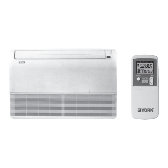
- Page 1 MINISPLIT Floor / Ceiling MCC - MCH Infrared remote control MOC - MOH 035 T 700049 - 001...
-
Page 2: Table Of Contents
- Filter Access.........................8 - Wiring Diagram......................9 - Service and Maintenance....................9 - Technical Appendix....................10 - Accessories.......................10 Parts List : (Contact York) Decommissioning,Dismantling and Disposal 1 - Safety 2 - Indoor & Outdoor Units 2.1 - Indoor Units Installation and maintenance of this air conditioning system Each Unit is shipped with the following items: should only be carried out by trained and qualified personnel. -
Page 3: Technical Specifications
Dimensions and Weights Indoor/Outdoor 990/850 D(mm) 199/230 199/280 199/230 199/287 27/59 26/36 26/38 29/65 4 - Dimensions Indoor Unit : MCC/MCH 09-25 Outdoor Unit : MOC/MOH 09-18 Outdoor Unit : MOC/MOH 25 Unit dimensions are shown in the Technical Specifications table above. -
Page 4: Installation
5 - Installation Unit installation entails: Outdoor unit placement - unit mounting - refrigerant piping connections - condensate water drainage connections - unit wiring connections. 5.1 - Unit clearances A minimium of clearance is necessary around the units to ensure proper air circulation and easy access for maintenance. Clearance required for indoor units ←... - Page 5 Drill holes for fastners to attach brackets to wall or ceiling. installation screw Use 12 mm. fastners suitable for the wall or ceiling material. Under Ceiling Bracket MCC -MCH 09-25 90 cm. Slide the unit into the brackets as shown below. 20 cm. Wall Mount Now, securely tighten the hex bolts on both sides.
-
Page 6: Condensate Drainage
6 - Condensate Drainage Drain tube on unit is flexible and can be routed to suit various piping arrangements. The drainage Install the drain hose. line must include an elbow trap (U bend). Be sure to arrange the drain hose so that it is leveled lower than the drain hose connecting port of the indoor unit. -
Page 7: Unit Controller Operation
8 - Unit Controller Operation EMERGENCY OPERATION ROOM TEMPERATURE SETTING Press the TEMP button up or down to change the setting to the desired Units are equipped with a switch to run in emergency operation mode. room temperature. The setting range is from 16°C to 32°C.Operating The switch is on the infrared receiver board where the LED lights are the unit below 18°C may result in the coil freezing. -
Page 8: Filter Access
After the unit has either been started or stopped by the timer, the set The Diagnostic Information is reported via different flashing patterns time will remain in the program, however the start or stop button must of the 3 indicator lights on the unit. The chart below shows the light be pressed again to reset the timer function. -
Page 9: Wiring Diagram
10 - Wiring Diagram MCH/MOH 09 - 25 - Heat Pump Units MCC/MOC 09 - 25 Cooling Only Units Indoor Indoor unit unit Outdoor unit Outdoor Power Supply Power Supply unit 220-240V/1Ph/50Hz 220-240V/1Ph/50Hz 208-230V/1Ph/60Hz 208-230V/1Ph/60Hz MCH/MOH 25 - Heat Pump Units... -
Page 10: Technical Appendix
12 - Technical Appendix Capacity correction factor for piping length (C2) Unit Capacity Total cooling capacity can be detemined by using correc- Indoor unit tion factors C1, C2 and C3. Piping length (m) Given cooling capacity = Cooling capacity at standard Correction factor C2 1.00 0.98... - Page 11 MOC 07 to 55 and MOH 07 to 55 DESIGNATION : Indoor units MCC 07 to 35 , MCH 07 to 35, MSC 35 to 55, MSH 35 to 55, MKC 12 to 55, MKH 12 to 55, MAC 18 to 55, MAH 18 to 55 IS IN COMPLIANCE WITH REQUIREMENTS OF : •...
- Page 12 DE - COMMISSIONING DISMANTLING & DISPOSAL This product contains refrigerant under pressure, rotating parts, and electrical connections which may be a danger and cause injury! All work must only be carried out by competent persons using suitable protective clothing and safety precautions. Read the Manual Risk of electric shock Unit is remotely controlled and...
Need help?
Do you have a question about the MCC and is the answer not in the manual?
Questions and answers