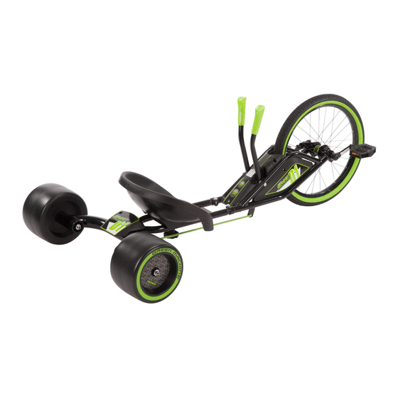
Huffy green machine Owner's Manual
Gm 16”
Hide thumbs
Also See for green machine:
- Owner's manual (118 pages) ,
- Owner's manual (21 pages) ,
- Owner's manual (24 pages)
Advertisement
Quick Links
Download this manual
See also:
Owner's Manual
Owner's Manual
Assembly Instructions
Date of Purchase: ___________________
Apply ID / Tracking
Please write the date of purchase.
Label Here
You should also retain the sales receipt.
GM 16" Assembly Manual v071712
Copyright Huffy Corporation 2012
THIS DOCUMENT CONTAINS IMPORTANT SAFETY INFORMATION.
READ AND KEEP FOR FUTURE REFERENCE
Advertisement

Summary of Contents for Huffy green machine
-
Page 1: Assembly Instructions
Apply ID / Tracking Please write the date of purchase. Label Here You should also retain the sales receipt. GM 16” Assembly Manual v071712 Copyright Huffy Corporation 2012 THIS DOCUMENT CONTAINS IMPORTANT SAFETY INFORMATION. READ AND KEEP FOR FUTURE REFERENCE... -
Page 2: Safety Information
Safety Information WARNING Continued: • Understand all operating procedures before riding. PLEASE READ AND FULLY UNDERSTAND THIS OWNERS MANUAL BEFORE • Do not add a motor to the product. OPERATING THE PRODUCT • Do not modify the product. • Before each ride check all screws and fasteners; re-tighten any that are loose. Replace any fasteners that are damaged. -
Page 3: Limited Warranty
IF YOU HAVE ANY QUESTIONS REGARDING THE OPERATION OF THIS PRODUCT, PLEASE REFER TO THIS OWNERS MANUAL OR CALL CUSTOMER SERVICE Limited Warranty Part or model specifi cations are subject to change without notice. This Limited Warranty is the only warranty for this product. There are no other expressed or implied warranties. The only uses for this product are described in this manual. Warranty registration is not required. - Page 4 NOTE: APPLY LABELS PRIOR TO ASSEMBLY LABEL SHEET (both sides) (both sides) “Huffy” and “Green Machine” are registered trademarks of Huffy Corporation...
- Page 5 note (x2) note WING BOLT MUST BE FULLY TIGHTENED BY HOLDING WING BOLTS note AT BOTH ENDS OF AXLE.
- Page 7 Limiter Pin...
- Page 8 note ENSURE BUSHING IS IN PLACE BEFORE ASSEMBLY...
- Page 9 WING BOLT MUST note BE FULLY TIGHTENED BY HOLDING WING BOLTS AT BOTH ENDS OF AXLE. (both wheels)
- Page 10 OPPOSITE SIDE note...
- Page 11 ROUND HOLES HEX HOLES note note ORIENTATION note OF NUT...
- Page 12 INSERT SCREWS FIRST note note TURN UNIT UPSIDE DOWN...
- Page 13 BOTTOM BOTTOM...
- Page 15 (U-Bolt) (flag) (wingnut x 2) (seat) (left arm) (pin) (fender) (keeper) (screws x 6) (cap) (steering linkage) (screw x 1) (frame) (steering linkage) (wheel) (stearing limiter) (rear frame) (bushing x 2) (axle shaft) (right arm) (washer x2) (cap x2) (nut x2) bushing (wing bolt x2) (bushing x2)
-
Page 16: Assembly Parts List
ASSEMBLY PARTS LIST PAGE-ID PART No. DESCRIPTION PAGE-ID PART No. DESCRIPTION Label Sheet vLabel Sheet End Cap (x2) Main Frame Bushing (x1) Left Arm Washer (x1) Right Arm Wing bolt (x1) Steering Shaft Hub Cap (x1) Washer (x1) Tire (x1) Wing Bolt (x1) Bushing (x2) Cap (x2)


Need help?
Do you have a question about the green machine and is the answer not in the manual?
Questions and answers