
Related Manuals for ProsKit MT-1710


Summary of Contents for ProsKit MT-1710
- Page 1 MT-1710 3-3/4 True-RMS Auto Range Multimeter User’s Manual Edition, 2013/11/21 © 2013 Copyright by Prokit’s Industries Co., Ltd.
-
Page 2: Safety Notes
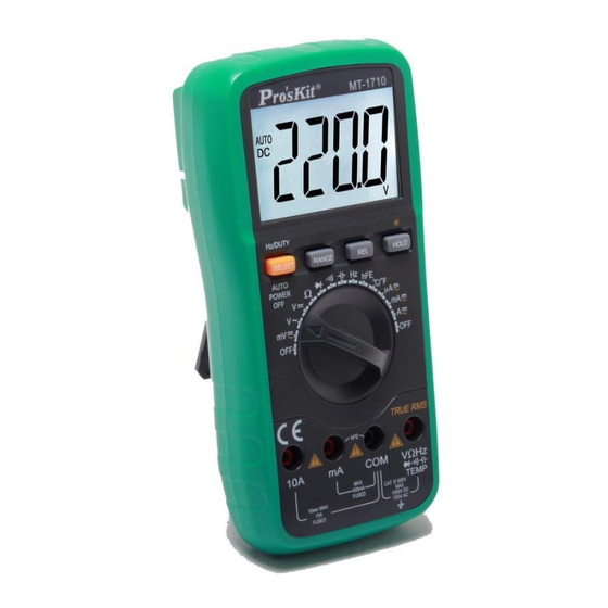
In addition, the design of backlight and overload protection is convenient for operation. The function of MT-1710 is to measure DCV, ACV, DCA, ACA, Resistance, Capacitance, Frequency, Temperature, Transistor, Diode and Continuity test. The instrument which adopts dual-integral A/D converter is an excellent meter. -
Page 3: Electrical Specifications
3.2 ELECTRICAL SPECIFICATIONS Accuracy is ± (RDG × a% + the lowest digit) at (23±5)℃,<75%RH. DC Voltage mV: Range Accuracy Resolution 400mV ±(0.5%+4) 0.1mV Input Impedance: >40MΩ Overload Protection: 1000V DC or 750V AC peak value DC Voltage: Range Accuracy Resolution ±(0.5%+4) 10mV... - Page 4 DC Current: Range Accuracy Resolution 400uA 0.1uA ±(1.0%+10) 4000uA 40mA 10uA ±(1.2%+8) 400mA 100uA ±(1.2%+10) 10mA Max. Measuring Voltage Drop: Full scale mA range: 400mV A range: 100mV Max. Input current: 10A (less than 10 seconds). Overload protection: 400mA/250V fuse, 10A/250V fuse. AC Current (True RMS):...
- Page 5 Capacitance: Range Accuracy Resolution 10nF ±(5.0%+20) 10pF 100nF 100pF 1u F ±(3.5%+8) 10uF 10nF 100uF 100nF 1mF/10mF/100 mF ±(5.0%+10) 1 uF/10 uF/100 uF Overload Protection: 250V DC/AC peak value Frequency: Range Accuracy Resolution 100Hz 0.01Hz 1000Hz 0.1Hz 10kHz ±(0.5%+10) 100kHz 10Hz 1MHz 100Hz...
-
Page 6: Operation
Temperature: Range Value Test condition <400℃ ±(1.0%+5) (-20-1000)℃ 1℃ ≥400℃ ±(1.5%+15) <752℉ ±(1.0%+5) (-4-1832)℉ 1℉ ≥752℉ ±(1.5%+15) Sensor: K type Warning: Do not input voltage at the range for safety. 4. OPERATION 4.1 Front Panel and Description: 1. LCD: display the measuring value and unit. 2. -
Page 7: Ac Voltage True-Rms Measurement
4. Connect the test leads to the tested point, the voltage and polarity that are connected with the red lead will appear on LCD. Note: 1. Manual measurement if LCD displays "OL", it means over range. Please set the range knob to a higher range. 2. -
Page 8: Dc Current Measurement
Note: Manual measurement, if LCD displays "OL", it means over range. Please set the range knob to a higher range. Do not measure over 750V ACV, or the meter will be damaged. Caution to avoid contact with high voltage circuits when measuring high voltage. -
Page 9: Capacitance Measurement
To use manual method, if the resistance range is unknown beforehand, switch the FUNCTION to a higher range and work down. When LCD displays "OL" signal, it means over-range. If measured resistance is more than 1MΩ, the meter may take a few seconds to stabilize. -
Page 10: Diode And Continuity Test
4.11 hFE Measurement: Switch the function to hFE range. Check the transistor is NPN or PNP type, insert the emitter, base and collector separately to the correct hole, the approximate value will be displayed on LCD. 4.12 Diode and Continuity Test: Connect the BLACK test lead to “COM”... -
Page 11: Auto Power Off
4.16 Auto Power Off: Whenever the meter is idle for 15mins, it is automatically off and enters sleep mode. The buzzer will sound before power-off. Press any key to turn on the power. Press “SELECT” key before turning on the meter. The meter will cancel power-off function automatically. -
Page 12: Troubleshooting
6 When LCD displays “ ”, the battery should be replaced. a. Ensure that the instrument is not connected to any external circuit. Set the selector switch to OFF position and remove the test leads from terminals. b. Remove the screw on the back of cover and take battery cover away. c. - Page 13 3-3/4 真有效值自動換檔電錶使用手冊 1. 產品概述 Pro’sKit MT- 1710 3-3/4 真有效直自動換檔電錶是一台性能穩定 、 可靠性高的電池驅 動數位萬用電錶。它採用了 25mm 字高的 LCD 顯示器,擁有背光顯示及超載保護功 能,更方便使用者操作。 該儀器具有測量 DCV、ACV、DCA、ACA、電阻、電容、頻率、溫度、電晶體、二 極體和通斷測試的功能,採用雙積分 A / D 轉換的核心處理器,是一台性能優越的工 具儀錶,適合在實驗室、工廠、家庭使用及無線電愛好者的理想工具。 2. 安全注意事項 該儀錶的設計符合 IEC1010 標準。操作之前,請先閱讀安全注意事項。 1. 測量電壓時,請勿輸入超過直流 1000V 電壓或交流 750V 有效值的極限電壓。 2. 電壓低於 36V 為安全電壓,當測量電壓高於 36V DC/25V AC,請檢查連接測 試錶棒是否可靠接觸、正確連接、絕緣良好,以避免觸電。...
- Page 14 直流毫伏 (DCmV): 量程 準確度 分辨力 400mV ±(0.5%+4) 0.1mV 輸入阻抗:> 40MΩ 超載保護:1000V 直流或 750V 交流峰值 直流電壓 (DCV): 量程 準確度 分辨力 ±(0.5%+4) 10mV 400V 100mV 1000V ±(1.0%+6) 輸入阻抗:10MΩ 超載保護:1000V 直流或 750V 交流峰值 交流毫伏真有效值 (ACmV True RMS): 準確度 量程 分辨力 40Hz-200Hz 200Hz-1kHz ±(1.6%+8) ±(8.0%+15) ±(1.6%+8) 400mV...
- Page 15 直流電流 (DCA): 量程 準確度 分辨力 400uA 0.1uA ±(1.0%+10) 4000uA 40mA 10uA ±(1.2%+8) 400mA 100uA ±(1.2%+10) 10mA 最大測量電壓降:滿量程 mA 為 400mV 的範圍,A 為 100mV 最大輸入電流:10A(不超過 10 秒) 超載保護:400mA /250V 保險絲,10A/250V 保險絲 交流電流真有效值 (ACA True RMS): 準確度 量程 分辨力 40Hz-200Hz 200Hz-1kHz 400uA 0.1uA ±(1.5%+10) 4000uA...
- Page 16 電容 (F): 量程 準確度 分辨力 10nF ±(5.0%+20) 10pF 100nF 100pF 1u F ±(3.5%+8) 10uF 10nF 100uF 100nF 1mF/10mF/100 mF ±(5.0%+10) 1 uF/10 uF/100 uF 過載保護:250V 直流或交流峰值 頻率 (Hz): 量程 準確度 分辨力 100Hz 0.01Hz 1000Hz 0.1Hz 10kHz ±(0.5%+10) 100kHz 10Hz 1MHz 100Hz 30MHz 1kHz...
- Page 17 溫度 (℃/℉): 量程 顯示值 測試條件 <400 ±(1.0%+5) ℃ (-20-1000)℃ 1℃ ≥400 ±(1.5%+15) ℃ <752 ±(1.0%+5) ℉ (-4-1832)℉ 1℉ ≥752 ±(1.5%+15) ℉ 感測器:K 型 警告:為了安全在此量程請勿輸入電壓 4. 使用方法 4.1 操作面板說明: 1. 液晶顯示器︰顯示測量值和單位 2. 功能鍵 2-1. “SELECT/HzDUTY”鍵:交直流電壓電流 DC / AC 選擇,測量直流電壓電流時,按此 鍵可切換測量交流電壓及電流。測量頻率 時,切換測量占空比(1~99%),測量溫度 時,切換攝氏和華氏模式...
- Page 18 注意事項: 1 手動量程模式,如果 LCD 顯示“OL ”,表明已超過量程範圍,需將測量範圍調高 一檔位。 2 不要測量超過 1000V 以上直流電壓,否則會損壞儀錶。 3 注意測量高電壓電路時,應避免觸及高壓電路。 4.3 直流毫伏電壓測量: 1 將黑色測試錶棒插入“ COM ”插孔,紅錶棒插入“ VΩHz ”插孔。 2 將功能開關旋至“mV ”檔。 3 測量的電壓低於 400mV,在該檔位沒有自動量程功能。 4 將測試錶棒接觸測試點,紅錶棒所接的該點電壓與極性顯示在 LCD 上。 注意事項: 1 如果 LCD 顯示“OL ”,表明已超過量程範圍,需將測量範圍轉致高一檔位,轉到 有 AUTO 測量功能的檔位。 2 切勿用高壓>400mV 在該檔位測量,否則會損壞儀錶。...
- Page 19 4.6 直流電流測量: 1 將黑色錶棒插入“ COM ”插孔,紅錶棒插入“mA” ( 最大 400 毫安培) 或“10A ” ( 大 10A)插孔。 2 將功能開關轉至電流檔位,按“SELECT”鍵選擇直流測量模式,然後將儀錶的錶 棒串接到被測電路上 , 被測電流值及紅色錶棒點的極性將同時在 LCD 上顯示 。 注意事項: 1 如果被測量的電流值是未知的,應將量程開關轉到最高的檔位, 然後依據顯示 值轉到相應的檔位上。 2 如果 LCD 上顯示“ OL”,則表示已經超過量程範圍,須將量程開關轉至高一檔。 3 最大輸入電流為 400mA 或 10A,視紅錶棒插入的位置而定,超過額定電會燒保 險絲,甚至損壞儀錶。 4 禁止在“COM ”、“mA”或“A”端,輸入高於直流 36V 或交流 25V 峰值電壓。 4.7 交流電流真有效值測量:...
- Page 20 4 當檢查電路中的電阻時,確保電路中的電源已關閉,所有電容完全放電才能測 量。 5 請勿在電阻檔內輸入電壓。 4.9 電容測量: 1 將功能開關轉至〞 〞檔位。 2 將黑錶棒插入“COM”插孔,紅錶棒插入“ VΩHz ”插孔。 3 如果在 LCD 上顯示的數位不是零,按“ REL”調整到零。 4 將被測電容對應引腳插入測試錶棒“ VΩHz ”插孔,被測電容負端接入“COM”插 孔,測量值將被顯示在 LCD 上。 注意事項: 1 電容測量沒有手動量程功能。 2 在每次測量之前,必須按“REL ”鍵,以確保測量準確。 3 對被測電容應該完全放電後測量,以避免損壞儀錶。 4 200uF 以上測量讀數穩定,大約為 15 秒。 4.10 頻率測量: 1 將錶棒或遮罩電纜插入“COM”和“...
- Page 21 4 反向測量:將黑色錶棒連接到被測二極體的正極,紅色錶棒連接到負極,顯示 器顯示“ OL ”。 5 完整的二極體測試應該包括正反向測試,如果測試結果與以上不符,說明二極 管損壞. 6 將功能開關轉至 檔位,可進行通斷測量 7 把錶棒連接到待測電路的兩點,如果電阻小於 40±30Ω,則內置蜂鳴器發出聲 音。 注意:請勿在 或 時輸入電壓。 4.13 溫度測量: 1 將功能開關轉至“ / ” ℃ ℉ 檔位。 2 將熱電偶傳感器的冷端(黑色插頭)負極插入〞COM〞端,熱電偶傳感器的工作 端(紅色插頭)正極插入“ VΩHz ”插孔,將探測頭置於被測場地,測量值將被顯 示在 LCD 上。 3 按“SELECT”鍵選擇攝氏/華氏顯示模式。 注意事項: 1 當輸入端開路,將顯示“常溫” 2 請勿隨意更換測溫傳感器,否則將不能保證測量準確度。...
- Page 22 7. 若儀器與電流互感器配合使用,應該小心開路時,端子部份的電壓狀況。 8. 確保測試線和表棒表面完好,表面沒有任何損壞絕緣的情況出現。 9. 注意不要超過允許的測量限制範圍使用。 10. 保險絲管的更換必須是正確的類型和規格。 11. 打開儀器更換電池或保險絲前,必需斷開測試表棒與任何外部電路的連接,將 功能選擇開關置於“關”的位置。 6.儀錶保養 該儀錶是一台精密的測量儀器,請使用者不要隨意修改內部電路,以免發生危險。 1. 保持萬用錶乾燥,並注意防塵,防水,防摔。 2. 不宜在高溫高濕、易燃易爆和強磁場環境下存放及使用儀錶。 3. 本儀器宜輕拿輕放,雖然有防震膠套保護,但嚴重跌落依然有可能損壞內部 電路及殼體,影響儀器正常工作及使用。 4. 請使用濕布和溫和的清潔劑清潔儀錶外觀,不要使用研磨劑及酒精等烈性溶 劑。 5. 如果長時間不使用,電池應更換。應該取出電池,防止電池漏液腐蝕儀錶。 6. 注意電池使用情況,當 LCD 顯示“ ”時,應該更換電池,步驟如下︰ 拆下後蓋上固定電池的螺絲,取下電池蓋。 取出 9V 不良電池 , 換上同類型的新電池 。 雖然任何 9V 電池都可使用 , 但 為長時間使用,推薦使用鹼性電池。...
- Page 23 7.故障排除 如果你的儀錶不能正常運作,下面的方法可以幫助你快速解決一般問題,如果故障 仍無法排除,請與維修中心或經銷商聯繫,我們將儘快協助您處理。 故障現象 檢查部位及方法 電源未接通 沒顯示 電池失效,請更換 符號出現 電池電力不夠,請更換電池 電流無法測量 保險絲損壞,請更換保險絲 測量誤差大 檢查並更換電池 本說明書如有變更,恕不通知。 本說明書基本內容正確,若有錯誤、遺漏之處,請與經銷商聯繫。 本公司不承擔由於用戶不正當操作所引起的事故和危害。 本說明書所講述的操作功能外,請勿將產品做其他特殊用途。...
Need help?
Do you have a question about the MT-1710 and is the answer not in the manual?
Questions and answers