Table of Contents
Advertisement
Quick Links
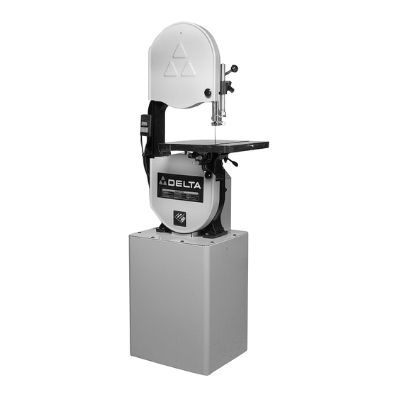
14" Metal/Wood Cutting
Band Saw
(Model 28-348)
PART NO. 426-03-651-0013 - 1-31-06
Copyright © 2006 Delta Machinery
To learn more about DELTA MACHINERY
visit our website at: www.deltamachinery.com.
For Parts, Service, Warranty or other Assistance,
1-800-223-7278 (
1-800-463-3582).
please call
In Canada call
Advertisement
Table of Contents

Subscribe to Our Youtube Channel
Related Manuals for Delta 28-348


Summary of Contents for Delta 28-348
- Page 1 14" Metal/Wood Cutting Band Saw (Model 28-348) PART NO. 426-03-651-0013 - 1-31-06 Copyright © 2006 Delta Machinery To learn more about DELTA MACHINERY visit our website at: www.deltamachinery.com. For Parts, Service, Warranty or other Assistance, 1-800-223-7278 ( 1-800-463-3582). please call...
-
Page 2: General Safety Rules
If you have any questions relative to a particular application, DO NOT use the machine until you have first contacted Delta to determine if it can or should be performed on the product. - Page 3 13. USE RECOMMENDED ACCESSORIES. The use of accessories and attachments not recommended by Delta may cause damage to the machine or injury to the user. 14. USE THE PROPER EXTENSION CORD. Make sure your extension cord is in good condition. When using an extension cord, be sure to use one heavy enough to carry the current your product will draw.
-
Page 4: Additional Safety Rules For Band Saws
11. NEVER START THE MACHINE with the workpiece against the blade. 12. HOLD WORKPIECE FIRMLY against the table. DO NOT attempt to saw a workpiece that does not have a flat surface against the table. 13. HOLD WORKPIECE FIRMLY and feed into blade at a moderate speed. -
Page 5: Grounding Instructions
A separate electrical circuit should be used for your machines. This circuit should not be less than #12 wire and should be protected with a 20 Amp time lag fuse. If an extension cord is used, use only 3-wire extension cords which have 3- prong grounding type plugs and matching receptacle which will accept the machine’s plug. -
Page 6: Functional Description
The Delta Model 28-348 has a large 16"x16" cast iron table that can be tilted 45 degrees to the right and 8 degrees to the left. The band saw also comes with a 4"... -
Page 7: Unpacking And Cleaning
2. Remove the two bolts (B) Fig. 2, with a 1/2" wrench, that attach the motor to the packing skid (A) 3. Remove the bolts that attach the stand (C) Fig. 3, and the saw (D) to the the packing skid (A) with a 3/8" wrench. Fig. 2... - Page 8 14. Motor Pulley 15. 5/16-18x1½" Hex Head Screw (4) 16. 5/16-18x3/4" Carriage Head Bolt (16) 17. #10-24x1/2" Socket Head Cap Screw (8) BAND SAW PARTS 18. #10-32x1/2" Pan Head Screw (4) 19. 5/16" Flat Washer (4) 20. 7/16-14 Jam Nut (2) 21.
- Page 9 FOR YOUR OWN SAFETY, DO NOT CONNECT THE MACHINE TO THE POWER SOURCE UNTIL THE MACHINE IS COMPLETELY ASSEMBLED AND YOU READ AND UNDERSTAND THE ENTIRE INSTRUCTION MANUAL. MOTOR BRACKET TO CABINET 1. Place the cabinet on its side as shown in Fig. 6. 2.
-
Page 10: Dust Chute
TOP PLATE TO CABINET NOTE: IF YOUR MACHINE IS SUPPLIED WITH AN LVC STARTER BOX, PLEASE REFER TO THE SUPPLEMENTAL INSTRUCTION MOUNTING THE LVC BOX TO THE STAND. THEN PROCEED AS FOLLOWS. 1. Place the top plate (A) Fig. 10, on the top of the cabinet (B). - Page 11 BAND SAW USED WITH A DUST COLLECTOR 3. If you are going to use your band saw with a dust collector, attach the dust port as follows: A. Align the four holes in the dust port (A) Fig. 15, with the four holes in the side of the stand.
- Page 12 5. Align the two holes in the hinge (C) Fig. 19, with the two holes in the cabinet door (D). MAKE SURE THAT THE HINGE OPENING IS POINTING DOWN. 6. Insert #10-24x1/2" socket head cap screws through the holes in the door, and thread the screws into the holes in the hinge.
-
Page 13: Motor Pulley
23, IS ON THE SIDE OF THE CABINET WITH THE BELT OPENING (B). 2. Align the four holes in the saw with the four holes in the top of the cabinet. 3. Place 5/16" flat washers on a 5/16-18x1½" hex head screws. - Page 14 TABLE TO SAW 1. Align the two table studs (A) Fig. 27, on the bottom of the table, with the two holes in the trunnion assemblies (B). Place table on trunnion assemblies. NOTE: MAKE SURE THE SLOT (C) FIG. 27, IN THE TABLE IS FACING AWAY FROM THE ARM (D).
-
Page 15: Table Insert
INSTALLED AS SHOWN IN FIG. 33. IF NOT, TURN BLADE INSIDE OUT. Slide the band saw blade, (teeth facing out), through the slot (E) Fig. 31, in the band saw table. 5. Place the blade around the two wheel assemblies (A) Fig. - Page 16 Fig. 34 from the switch box (B). 2. Insert two screws (C) Fig. 35, located on back of switch box, into two holes (D) located in the band saw arm. 3. Use the two nuts and lockwashers (L) Fig. 36, removed in STEP 1, to fasten the switch box to the bandsaw arm.
-
Page 17: Tilting The Table
DISCONNECT POWER SOURCE. 2. The table on the band saw can be tilted 45 degrees to the right and 9 degrees to the left. To tilt the table to the right, loosen the two clamp handles (A) Fig. 43, tilt the table to the desired angle as shown on the scale (D) Figs. - Page 18 ADJUSTING THE TABLE STOPS To adjust the 90 degree stop DISCONNECT POWER SOURCE. 2. Loosen the table clamp handles (A) Fig. 43, and tilt the table to the right. 3. Rotate the stop (B) Fig. 45 out of the way. 4.
-
Page 19: Adjusting Blade Tension
5. Move the blade tension handle to the left until the lever lock (B) Fig. 49 engages the blade tension lever handle (A). 6. The band saw blade tension can be fine tuned by turning adjustment nut (N) Fig. 51, while the blade is tensioned. -
Page 20: Tracking The Blade
(B). 4. Adjust the guides (A) Fig. 55 so that the front edge of the guides are just behind the “gullets” of the saw teeth. The complete guide block bracket can be moved in or out by loosening the thumb screw (C) and turning the knurled knob (D) Fig. -
Page 21: Changing Speeds
(D) Fig. 56 so that it is about 1/64" behind the back of the blade. CHANGING SPEEDS An advantage of this machine is that it can be changed instantly from a slow-speed metal cutting band saw to a high- speed wood cutting band. DISCONNECT MACHINE FROM POWER SOURCE. - Page 22 Light pressure on the work piece will produce a smoother cut, and prevent excess friction, and heating of the blade. KEEP THE SAW BLADE SHARP. Very little forward pressure is required for normal cutting. Keep the workpiece moving at a slow and consistent rate against the blade to ensure a smooth and accurate cut.
-
Page 23: Troubleshooting Guide
When withdrawing the piece being cut, changing the cut, or for any other reason, be careful not to accidentally draw the blade off the wheels. In most cases, it is easier and safer to turn the stock and saw out through the waste material, rather than try to withdraw the stock from the blade. - Page 24 Trouble: BAND SAW DOES NOT COME UP TO SPEED. Probable Cause 1. Low voltage due to improper extension cord size. 2. Low voltage. Trouble: BLADES BREAK. Probable Cause 1. Blade not tensioned properly. 2. Blade guides improperly adjusted. 3. Blade support bearing improperly adjusted.
-
Page 25: Band Saw Blades
This will save blades and will produce better cuts. For cutting wood and similar materials, Delta offers blades in widths of 1/8", 1/4", 3/8", 1/2" and 3/4". Delta also offers several 1/2" blades for metal cutting of different teeth per inch configurations. -
Page 26: Changing The Blades
Builders Board Hardwoods Plywoods Softwoods NOTE: Some types of plastics lend themselves to more pronounced results with the regular saw blades. Sheets under ¼” thickness and tubing under ¼” wall thickness are not adapted to skip tooth blades. WIDTH 1/8” 3/16”... - Page 27 Two Year Limited New Product Warranty Delta will repair or replace, at its expense and at its option, any new Delta machine, machine part, or machine accessory which in normal use has proven to be defective in workmanship or material, provided that the customer returns the product prepaid to a Delta factory service center or authorized service station with proof of purchase of the product within two years and provides Delta with reasonable opportunity to verify the alleged defect by inspection.
- Page 28 Delta products should be obtained by contacting any Porter-Cable · Service Center, or Porter-Cable Delta Factory Service Center. If you do not have access to any of these, call 800-223-7278 and you will · be directed to the nearest Porter-Cable Delta Factory Service Center.
Need help?
Do you have a question about the 28-348 and is the answer not in the manual?
Questions and answers