Asko TL751 Service Manual
Hide thumbs
Also See for TL751:
- Service manual (61 pages) ,
- Operating instructions manual (43 pages) ,
- Brochure (2 pages)
Table of Contents
Advertisement
Advertisement
Table of Contents

Related Manuals for Asko TL751


Summary of Contents for Asko TL751
- Page 1 Version2.2 2008.12.11 Service Guide Tumble dryer Asko TL751 / G / CA / XXL...
-
Page 2: Table Of Contents
Contents What is a Dryer? .................................2 Dryer Specification................................4 Operating Mechanism Diagram (Gas Type) ........................5 Operating Mechanism Diagram (Electric Type) ........................6 Mechanism by Ass’y (Electric Type)..........................7 Mechanism by Ass’y (Gas Type) ............................8 Parts List by Ass’y................................9 PCB Function Specification .............................23 Drum Dryer Troubleshooter .............................37 Dryer Installation ................................41 Electrical Requirements For Electric Dryers........................42 Dryer Service Notices ..............................49... -
Page 3: What Is A Dryer
What is a Dryer? 1. What is a Dryer? A lifter, operated by a rotating drum, rolls laundry in the drum, and hot air heated by electricity (or gas) dries the laundry through time or sensor dry system (a temperature control system) under various conditions. 2. - Page 4 3. Key Functions Dry Time • Adjust the length of time for drying. Sensor Dry • Automatically dry according to the types of laundry. Rack Dry • Dry sensitive shoes and fabric(e.g. sweaters, silk, lingerie) on the rack. Anti-crease • Prevent wrinkles in case laundry stays in the drum after the drying process. Damp Signal •...
-
Page 5: Dryer Specification
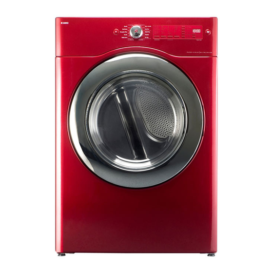
Dryer Specification 1. Product Look Parts FRAME DOOR O PROTECTOR GLASS PANEL FRONT CABINET FRONT PLATE TOP CABINET BUTTON FUNCTION BUTTON OPTION WINDOW COURSE DIA KNOB BUTTON DELAY BUTTON START BUTTON POWER WINDOW DISPLAY Dimensions 27" (68.6cm)x 32" (81.2cm)x 40 3/8" (102.5cm)x52” (132cm) W x D x H x Depth with door open Weight 129 lb. -
Page 6: Operating Mechanism Diagram (Gas Type)
Operating Mechanism Diagram (Gas Type) Electric Input Operating Mechanism • Controller operation Program • Operator/gas burner/air supplier/ventilator operation • Automatic operation of the controller • Drying by the automatic sensor 1. Controller lifter • MAIN PCB plate top • FRONT PCB •... -
Page 7: Operating Mechanism Diagram (Electric Type)
Operating Mechanism Diagram (Electric Type) Electric Input Operating Mechanism • Controller operation • Operator/heater/air supplier/ventilator operation Program • Automatic operation of the controller • Drying by the automatic sensor 1. Controller • MAIN PCB lifter plate top • FRONT PCB •... -
Page 8: Mechanism By Ass'y (Electric Type)
Mechanism by Ass’y (Electric Type) PLATE TOP ASS'Y MAIN PCB ASS'Y CABINET ASS'Y DRUM SUPPORT REAR ASS'Y PANEL F ASS'Y DUCT IN LET ASS'Y DRUM SUPPORT FRONT ASS'Y CABINET F ASS'Y MOTOR ASS'Y DRUM ASS'Y... -
Page 9: Mechanism By Ass'y (Gas Type)
Mechanism by Ass’y (Gas Type) PLATE TOP ASS'Y MAIN PCB ASS'Y CABINET ASS'Y DRUM SUPPORT REAR ASS'Y PANEL F ASS'Y DUCT IN LET ASS'Y DRUM SUPPORT FRONT ASS'Y CABINET F ASS'Y GAS BURNER DRUM ASS'Y ASS'Y... -
Page 10: Parts List By Ass'y
Parts List by Ass’y 1. DRYER CBINET ASS'Y... - Page 11 For fixing Frame Upper to Cabinet COVER BACK 3611427900 SGCC 0.6T SCREW TAPPING 7112401411 T1 TRS 4x14 For fixing Cover Back COVER DUCT 3611428010 ABS, WHITE TL751/G/CA XXLW 3611428060 ABS, PLATINUM TL751/G/CA XXLPP 3611428070 ABS, RED ROSE TL751/G/CA XXLRR FIXTURE PLATE 3612008000 SCREW TAPPING 7121401211 T2S PAN 4x12 For fixing Plate T &...
- Page 12 2. DRYER MOTOR ASS'Y Part Name Part Code Description Qtt'y Remark BRACKET MOTOR 3610608500 SGCC 2.0T MOTOR DRYER 36189L5D00 AC 120V 60Hz CLAMP MOTOR 3611206000 SK5 0.7T BRACKET IDLER AS 3610609100 DWR-WE31 SPRING IDLER 3615115500 HSW3 SPECIAL BOLT 3616039000 S18A M6x10(FLANGE) SWITCH MICRO 3619047500 UL.
- Page 13 3. GAS BURNER ASS'Y not DC12V, please check. Part Name Part Code Description Qtt'y Remark VALVE GAS AS 3615417200 DC12V,130mA LPG type 3615417300 DC12V,130mA LNG type SCREW TAPPING T1 M4*8 For fixing G01 & G03 GUIDE BUNNER 3612511100 SGCC 1.0T MIXING VENTURI AS 3612209200 VENTURI AS+ FLAME DAMPER...
- Page 14 4. INLETDUCT ASS'Y 4-1. Electric Type 4-2. Gas Type Part Name Part Code Description Qtt'y Remark DUCT INLET REAR 3617510200 WE31'S, ALCOSTA 0.6T ELECTRIC TYPE 3617510210 WG31'S, ALCOSTA 0.6T GAS TYPE DUCT INLET FRONT 3617510300 WE31'S, ALCOSTA 0.6T ELECTRIC TYPE 3617510310 WG31'S, ALCOSTA 0.6T GAS TYPE...
- Page 15 5. SUPPORT DRUM REAR ASS'Y Part Name Part Code Description Qtt'y Remark SUPPORT DRUM REAR 3615304500 STS430 2B 0.8T BRACKET SUP.R-SIDE 3610608810 SGCC 1.0t BRACKET SUP.R-UPPER 3610608910 SGCC 1.0t SCREW TAPPING 7122401411 T2 TRS 4x14 MFZN For fixing bracket supp.up & side ROLLER AS 3614714400 ASSY...
- Page 16 6. SUPPORT DRUM FRONT ASS'Y Part Name Part Code Description Qtt'y Remark SUPPORT DRUM F 3615304600 SECD 0.8T HOUSING LAMP 3613053400 PP(Heat Resisting) SOCKET LAMP 3613053300 14 BASE LEAD WIRE TYPE LAMP 3613625400 AC 125V 15W WINDOW LAMP 3615505100 ABS(Transparent) SCREW TAPPING 7112401208 T1 TRS 4x12 SUS...
- Page 17 7. DRUM ASS'Y Part Name Part Code Description Qtt'y Remark DRUM 3617011000 STS430 J1L 0.5T LIFTER 361A401050 Heat resisting PP SCREW TAPPING 7122502008 T2S TRS 5x20 SUS For fixing lifter SEAL DRUM AS 3614010600 Felt + Synthetic leather PAD DRUM 3614111100 BUTYL BELT V...
- Page 18 Glass PROTECTOR GLASS 3618304300 Transparent ABS HINGE DOOR AS 3612903610 Zn-Dc, WHITE TL751/G/CA XXLW 3612903640 Zn-Dc, GRAY TL751/G/CA XXLPP, XXLRR CAP HINGE DOOR 3610916500 FRAME DOOR O 3612208120 ABS, SILVER DOOR TL751/G/CA XXLW 3612208110 ABS, CROM DOOR TL751/G/CA XXLPP, XXLRR...
- Page 19 9. PLATE TOP ASS'Y Part Name Part Code Description Qtt'y Remark PLATE TOP AS PRMACA3R00 WHITE TL751/G/CA XXLW PRMACA3R20 PLATINUM TL751/G/CA XXLPP PRMACA3R60 RED ROSE TL751/G/CA XXLRR HANDLE REAR 3615304100 (PLATE SUPPORTER) SCREW TAPPING 7122401411 T2S TRS 4x14 MFZN...
- Page 20 10. CABINET FRONT ASS'Y Part Name Part Code Description Qtt'y Remark CABINET FRONT AS 3610812510 WHITE TL751/G/CA XXLW 3610812550 PLATINUM TL751/G/CA XXLPP 3610812560 RED ROSE TL751/G/CA XXLRR GASKET CABINET F 3612323350 EPDM 5x10 3.0T R207 SUPPORT HINGE 3615304410 SGCC 1.6t...
- Page 21 11. PANEL F ASS'Y...
- Page 22 Part Name Part Code Description Qtt'y Remark PANEL F 3614288900 ABS + SILK PRINT, WHITE TL751/G/CA XXLW ABS + SILK PRINT, PLATINUM TL751/G/CA XXLPP ABS + SILK PRINT, RED ROSE TL751/G/CA XXLRR BUTTON POWER 3616637800 ABS + SILK PRINT, WHITE...
-
Page 23: Door Hanging
12. Procedure for Reversing the Door Door hanging 5. Next insert the hinge of the door securely in place of the left side of the front cabinet. The tumble dryer come with the door hinged on the right. However, it is possible to change the door to be hinged on the left. -
Page 24: Pcb Function Specification
PCB Function Specification 1. Front PCB Function Specification Comprehensive function specification of the unit including operation of a 27-inch dryer by drying courses and drying functions, control of electronic devices by PCB, operation by S/W, test function, error mode, and so on. Index Miscellaneous Descriptions... - Page 25 2. Detailed Descriptions 2-1. Setting by Courses 1) Sensor Dry Course COURSE - SENSOR DRY Synthetics Everyday Wear Towels Bulky Items Very Dry 1:01 1:05 1:05 1:10 More Dry 1:02 1:00 DRY LEVEL Normal Less Dry Damp Dry Dry Level Default Normal Normal Normal...
- Page 26 2) Manual Dry Course COURSE - MANUAL DRY Quick Dry FRESHEN UP AIR DRY TEMP Time CONTROL Temp Default High Mid high DRY LEVEL TEMP Ultra Low ~ High Ultra Low ~ High A. Only Temp is selected in Manual Dry Course. B.
- Page 27 2-2. Operation 1) Overview Different operation processes are applied to Sensor Dry Course and Manual Dry Course. Sensor Dry Course judges the condition of laundry with humidity/temperature sensors so as to decide appropriate dry level. Manual Dry Course dries laundry as per temperature conditions set by an operator. 2) Process of Sensor Dry Course A.
- Page 28 3) Process of Manual Dry Course A. Power Button On “_ _ _” is displayed at 18:88 LED. “Check Filter” of Custom LED goes on and off before you press Start Button. “High” of initial Beeper goes on and the previous Beeper value is displayed when you switch on the power.
- Page 29 2-3. Operation of Load and Sensor 1) Operation of Heater - Electric Type On/Off goes on according to temperatures set or measured by the sensor. Regardless of the control by the microcomputer, however, the heater may go off if a temperature reaches Thermostat Off Temperature as per outlet conditions.
- Page 30 2-4. Operation of Buttons 1) Power A. The electric power switch turns on/off the display. B. Automatic switch off function 1 Power is immediately switched off after an operation is done. 2 Power is switched off after 10 minutes if no button is selected while power is on. C.
- Page 31 4) Temp Control A. If you press this button, the following is displayed in order. Medium - Mid High - High - Ultra Low - Low - Medium B. Each level targets temperatures as follows. (Target temperatures : Thermostat fan) Target Temperatures Level Heater-Off(°C)
- Page 32 8) Less Time A. Pressing this button decreases time by a minute. B. The time decreases up to 00:15 (minutes) C. You can change time in Manual Dry Course and Time Selection. Also Anti-crease can be selected/cancelled. 9) Delay Start A.
- Page 33 2-5. Option Rack Dry More Time Damp Programs Dry Sensor Temperature Anti-crease Less Time Signal Delay Start Default Normal High Bulky Items Select Default Normal High Towels Select Default Normal Mid.High Everyday Select Wear Default Normal Medium Synthetics Select Default Normal Gentle Select...
- Page 34 2-6. Error Mode 1) H1 error - Humidity sensor error 1 This occurs when there is a short defect in the humidity sensor (the indicated value is lower than 24) 2 The unit buzzes, indicating the error, every 10 minutes for 10 seconds. 3 The error display goes off when the power is switched on/off.
- Page 35 2-7. TEST Mode 1) PCB TEST MODE A. How to enter the mode: switch the power on while pressing Dry Level and Temp Control buttons. B. Operation order: check load by pressing Time Dry Button continually. Operation Load Time (Sec) DISPLAY Miscellaneous F PCB LED ALL On...
- Page 36 3. ELECTRIC DRYER PCB PIN LAYOUT...
- Page 37 4. GAS DRYER PCB PIN...
-
Page 38: Drum Dryer Troubleshooter
Drum Dryer Troubleshooter POWER/NOISE Trouble Symptom Cause Solution Service wire A fault of Lead-in wire power Call the electricity provider problem Fuse disconnection of service wire or an expert Disconnection of the power cable Replace the power cable (Connection fault) Dryer wire problem Disconnection of a controller terminal pin and Plug in the connector... - Page 39 1. ELECTRIC DRYER WIRING DIAGRAMS...
- Page 40 2. GAS DRYER(ON/OFF CONTROL) WIRING DIAGRAMS...
- Page 41 3. GAS DRYER(PROPOTIONAL CONTROL) WIRING DIAGRAM...
-
Page 42: Dryer Installation
Dryer Installation 1. Installation Order 1 Place the dryer on the flat ground. Keep the unit at least 12 inch away from the wall. 2 Check the 4 legs and the gap between the unit and floor. The dryer should stand stably when you try to move the unit to the left or right. -
Page 43: Electrical Requirements For Electric Dryers
ELECTRICAL REQUIREMENTS FOR ELECTRIC The following are additional instructions regarding electrical connections and requirements for electric dryers. Important Warning To help prevent fire, electric shock, serious injury or death, the wiring and grounding must conform to the latest edition of the National Electrical Code, ANSI/NFPA 70 and all applicable local regulations. Please contact a qualified electrician to check your home’s wiring and fuses to ensure that your home has adequate electrical power to operate the dryer. - Page 44 Review the following options to determine the appropriate electrical connection for your home: Use the instructions in this section if your home has Use the instructions in this section if your home has a 4-wire receptacle (NEMA type 14-30R) and you a 3-wire receptacle (NEMA type 10-30R) and you will be using a UL listed, 120/240 volt minimum, 30 will be using a UL listed, 120/240 volt minimum, 30...
-
Page 45: Wire Connection : Direct Wire
4-wire connection : Direct wire Important : Grounding through the neutral conductor is prohibited for (1) new branch-circuit installations, (2) mobile homes, (3) recreational vehicles, and (4) areas where local codes prohibit grounding through the neutral conductor. Prepare minimum 5 ft (1.52 m) of length in order for dryer to be replaced. - Page 46 3-wire connection : Direct wire Important : Grounding through the neutral conductor is prohibited for (1) new branch-circuit installations, (2) mobile homes, (3) recreational vehicles, and (4) areas where local codes prohibit grounding through the neutral conductor. Prepare minimum 5 ft (1.52 m) of length in order for dryer to be replaced.
- Page 47 Option 1: 4-wire connection with a power supply cord. • lf your local codes or ordinances do not allow the use of a 3-wire connection, or you are installing your dryer in a mobile home, you must use a 4-wire connection. 1.
- Page 48 Option 2: 3-Wire connection with a power supply cord. lf your local codes or ordinances permit the connection of a frame-grounding conductor to the neutral wire, use these instructions. If your local codes or ordinances do not allow the connection of a frame-grounding conductor to the neutral wire, use the instructions under Section 1: Optional 3- wire connection.
-
Page 49: Dryer Service Notices
Dryer Service Notices Service Parts Notices Replacing the Humidity sensor Be careful of the terminal connection humidity sensor Be careful of loose attachment Replacing/fixing panel f assy PCB/BUTTON/HARNESS Be sure that the panel f assy does not interfere in the drum after the service Replacing the lifter LIFTER... - Page 50 Electric Parts List - Electric Clothes Dryer Part Name Part Code Type No Rating Major Functions Lamp AS 3612625300 Lamp Holder: 4000 series 75W, 125V Power is applied to the lamp to turn up the light in the drum when the door is Lamp Base: E12 15W, 125V opened.
-
Page 51: Electric Parts List - Electric Clothes Dryer
Electric Parts List - Gas Clothes Dryer Part Name Part Code Type No Rating Main function Lamp Holder: 4000 series 75W, 125V Lamp AS 3612625300 Power is applied to the lamp to turn up the Lamp Base: E12 15W, 125V light in the drum when the door is opened. -
Page 52: Thermostat Fan
Thermostat Fan Part Code : 3619047900 1. Function • This is a bimetal-type switch which protects the clothes from damage by overheating. • If the exaust air is too hot, this thermostat stops the motor and after the air is cooled down, it restarts the motor. -
Page 53: Thermostat Cut-Out
Thermostat Cut-Out Part Code : 3619047800 1. Function • This is a bimetal-type switch which protects the heater from overheating. • If the heater is overheated abnormally, this thermostat cuts off the heater PERMANENTLY. • Note that this thermostat is NON-RESETTABLE; if it is opened, it should be replaced by new one. -
Page 54: Thermostat Hi-Limit
Thermostat Hi-Limit Part Code : 3619047600 1. Function • This is a bimetal-type switch which controls the heater operation. • If the heater is too hot, this thermostat stops the heater and after the heater is cooled down, it restarts the heater. 2. -
Page 55: Lamp Assembly
Lamp Assembly Part Code : 3612625300 1. Function • This is a lamp assembled with its bracket and window. • If the user opens the door, the door switch gives electric power to this lamp and it turns on. 2. Specification •... -
Page 56: Switch Door
Switch Door Part Code : 3619047700 1. Function • This is a switch that checks whether the door is open or closed. • If the user opens the door, this switch disconnects power supply to the motor and turns the lamp on. •... -
Page 57: Heater Assembly
Heater Assembly Part Code : 3612802500 1. Function • This is an assembly that heats air in the drum. • Two 2500-W upper/lower heaters are connected in a parallel circuit, producing 5,000W • According to the program set, either one or two heaters operate. 2. -
Page 58: Belt Switch (Switch Micro)
Belt Switch (Switch Micro) Part Code : 3619047500 1. Function • The switch cuts the power supply to the motor when a belt is broken. • The switch is on when the belt has adequate tension but off when the belt gets loosened or broken, blocking the power supply to the motor. -
Page 59: Thermistor Fan
Thermistor Fan Part Code : 361AAAAC20 1. Function • The fan senses the temperature of exhaust air. • The higher the temperature is, the smaller the resistance is. 2. Specification • Thermistor with following temperature-resistance characteristic. at 90°C : R = 4.43 kΩ at 40°C : R = 26.07 kΩ... -
Page 60: Motor Dryer
Motor Dryer Part Code : 36189L5D00 1. Function • The motor rotates the drum using the belt as well as the fan to expel wet air. • This is a shunt AC motor. When the motor begins to run, a centrifugal switch shorts out the operation coil. - Page 61 5 Drum Ass'y remove 7 Remove the cover fan and 3 screws. 6 Cover Fan remove Loosen the 3 screws as indicated with a circle. 8 Remove the 4 screws and the motor ass’y. Loosen the 3 screws as indicated with a circle. 9 Remove wires and 2 clamps that fix the motor bearing to detach the motor.
-
Page 62: Igniter As
Igniter As Part Code : 36189L5800 1. Function • Igniter for fuel gas ignition. • Igniter heats up quickly when power is supplied. If fuel gas is injected to the surrounding area of igniter, gas is ignited by the heat of igniter. 2. -
Page 63: Flame Sensor
Flame Sensor Part Code : 3614825700 1. Function • Sensor flame is the switch that operates by detecting fuel gas ignition or heating of igniter. • Contact point is opened when sufficient radiant heat is detected through the transparent window at the bottom of sensor. •... -
Page 64: Thermostat Hi-Limit
Thermostat Hi-Limit Part Code : 3619047610 1. Function • This is a bimetal-type switch which stops the burner overheating. • If the burner is too hot, this thermostat shuts off the gas valves and after the burner is cooled down, it allows the gas valves to operate. 2. -
Page 65: Thermostat Cut-Out
Thermostat Cut-Out Part Code : 3619047810 1. Function • This is a bimetal-type switch which protects the burner from overheating. • If the burner is overheated abnormally, this thermostat cuts off the gas valves PERMANENTLY. • Note that this thermostat is MANUALLY-RESETTABLE; by pressing the knob on the top, this part is returned to reusable state. -
Page 66: Valve Gas As
Valve Gas As Part Code : 3615417200, -7300 1. Function • Valve gas AS supplies or blocks off fuel gas. • 2 valves are horizontally connected to safely block off gas leakage. • Each valve is solenoid value. Gas passed through this valve is injected after being stabilized to the prescribed output pressure in regulator. -
Page 67: Dismantling Method Per Dryer Ass'y
DISMANTLING METHOD PER DRYER ASS'Y PANEL FRONT ASS’Y 1.Remove left cap and unfasten screw. 2. Separate panel front. (CAUTION : Internal hook damage attention) PLATE TOP ASS'Y 2. Remove 4 screws at the back. 1. Remove 3 screws at the front. 3. -
Page 68: Cabinet Front Ass'y
CABINET FRONT ASS'Y 2. Remove filter. 1. Remove 4 screws at the top. 3. Remove 3 screws. 4. Lift cabinet front in the direction of arrow and pull it forward. 5. Remove door switch connector. -
Page 69: Frame Upper / Separation Of Lamp,Pcb Main Connector
FRAME UPPER 1. Remove 2 screws from left and right in front 2. Remove 2 screws from left and right at the part. top. 3. Separate frame upper after removing harness at the back. SEPARATION OF LAMP,PCB MAIN CONNECTOR 1. Separate lamp connector. 2. -
Page 70: Pcb Main / Duct Outlet Ass'y
PCB MAIN 1. Remove 2 screws. 3. Separate frame upper after removing harness at the back. DUCT OUTLET ASS'Y 1. Remove 2 left and right screws. 2.Remove 1 screw. 3. Remove duct outlet F in the direction of... -
Page 71: Support Drum Front Ass'y / Drum Ass'y / Pipe Exhaust
SUPPORT DRUM FRONT ASS'Y 1. Push up idler in the direction of arrow to remove belt. Then, separate belt and remove drum. DRUM ASS'Y 1. Remove 1 rear screw and separate pipe exhaust in the direction of arrow. PIPE EXHAUST 1. -
Page 72: Cover Back / Support Drum Rear Ass'y
COVER BACK 1. Remove 10 screws. SUPPORT DRUM REAR ASS'Y 1. Remove heater terminal connection cable. 2. Remove 7 screws. 3. Remove support drum rear ass'y in the direction of... -
Page 73: Motor Connector
MOTOR CONNECTOR 1. Separation of temperature sensor: Separate connector. Remove 1 screw. 2. Separation of thermostat fan: Separate connector. Remove 2 screws. 3. Separation of micro switch: 4. Separation of motor connector. -
Page 74: Terminal Block
TERMINAL BLOCK 1. Remove cover terminal. 2. Remove 3 screws. -
Page 75: Motor Ass'y
MOTOR ASS'Y 1. Remove 6 screws and separate motor ass'y. 2. Separation of cover fan: Remove 2 screws. 3. Separation of impeller fan: Fix motor axis and separate fan. - Page 76 4. Dismantling of case fan: Remove 3 screws. 5. Dismantling of bracket motor: Remove 2 clamp motors each.
-
Page 77: Heater Ass'y / Lamp Ass'y
HEATER ASS'Y 1. Remove 4 screws. 2. Unfold 4 side fixing parts. 3.Remove thermostat 2 screws. 4.Remove 13 screws. LAMP ASS'Y 1. Remove 1 screw. -
Page 78: Filter Dust Ass'y / Humidty Sensor
FILTER DUST ASS'Y / HUMIDTY SENSOR 1. Filter dust ass'y: Remove 2 screws. 2. H/S: Remove connector. 3. Remove H/S. -
Page 79: Door Ass'y
DOOR ASS'Y 1. Separation of hinge and support drum front: Remove 2 screws. 2. Remove 13 screws. 3. Door lock ass'y: Separate door lock ass'y after removing 2 screws. - Page 80 4. Door switch...
-
Page 81: Gas Burner Ass'y
GAS BURNER ASS'Y 1. Remove 6 screws. And separate 2 valve connectors. 2. Remove 1 screws at the back of cabinet. 3. Remove 2 screws and separate igniter connecter. 3. Remove 2 screws after removing harness at thermostat Cut-Out, Hi-Limit. - Page 83 ABOUT THIS MANUAL ABOUT THIS MANUAL @ @ A A B B A A C C D D ! E E F F G G H H I I A A @ @ G G J J ! ! A A D D E E ? ? KL MNO PQR STU VWXY Z[ ^Q_ `...
Need help?
Do you have a question about the TL751 and is the answer not in the manual?
Questions and answers