Hamworthy Purewell Installation, Commisioning And Maintenance Instructions
Gas fired modular boiler systems atmospheric cast iron boiler 40kw to 120kw output permanent ignition controls standard draught diverter or low line draught diverter
Hide thumbs
Also See for Purewell:
Table of Contents
Advertisement
Quick Links
Homepage
Installation, Commissioning
and Servicing Instructions
Atmospheric Cast Iron Boiler
40kW to 120kW Output
PERMANENT IGNITION CONTROLS
Standard Draught Diverter
Low Line Draught Diverter
Purewell
Gas Fired
Modular Boiler Systems
IMPORTANT NOTE
THESE INSTRUCTIONS MUST BE READ AND UNDERSTOOD BEFORE
INSTALLING, COMMISSIONING, OPERATING OR SERVICING EQUIPMENT.
Register
or
NATURAL GAS
LPG-PROPANE
Contents
I
2 H
I
3P
Advertisement
Table of Contents

Subscribe to Our Youtube Channel
Related Manuals for Hamworthy Purewell


Summary of Contents for Hamworthy Purewell
- Page 1 Servicing Instructions Atmospheric Cast Iron Boiler 40kW to 120kW Output PERMANENT IGNITION CONTROLS Standard Draught Diverter Low Line Draught Diverter Purewell Gas Fired Modular Boiler Systems NATURAL GAS LPG-PROPANE IMPORTANT NOTE THESE INSTRUCTIONS MUST BE READ AND UNDERSTOOD BEFORE...
- Page 2 01202 662527 / 662528 To supplement the detailed technical brochures, technical advice on the application and use of products in the Hamworthy Heating range is available from our technical team in Poole and our accredited agents. SITE ASSEMBLY 01202 662555 Specialist teams are available for on site assembly of the full range of Hamworthy boilers (excluding Lulworth).
- Page 3 NOTE: THESE INSTRUCTIONS SHOULD BE READ AND UNDERSTOOD BEFORE ATTEMPTING TO INSTALL, COMMISSION OR OPERATE THIS UNIT THE PUREWELL BOILER IS INTENDED FOR USE AS A COMMERCIAL APPLIANCE AND IS NOT CERTIFIED FOR USE IN HABITABLE AREAS. THIS BOILER IS FOR USE ON GROUP H NATURAL GAS (2ND FAMILY)I...
- Page 4 THIS PAGE LEFT INTENTIONALLY BLANK HAMWORTHY HEATING LTD. PUREWELL PERMANENT IGNITION 500001045/F...
-
Page 5: Table Of Contents
Open Vent Pipe and Cold Feed Pipe Altitude Gauge (Water Pressure Gauge) Thermometer Drain Valves Circulating Pump Minimum Water Flow Rates Waterside Pressure Drop 8.10 Control Schemes 8.11 Unvented Pressurised Systems 8.12 Modular Boiler Control Schemes HAMWORTHY HEATING LTD. PUREWELL PERMANENT IGNITION 500001045/F... - Page 6 Pilotstat boiler wiring diagram..........Figure No. 15 Diagram of igniter assembly............ Figure No. 16 Diagram of Various gas valves fitted........Figure No. 17 Pilotstat valve assembly............Figure No. 18 General Fault Finding.............. 30/31 HAMWORTHY HEATING LTD. PUREWELL PERMANENT IGNITION 500001045/F...
-
Page 7: Introduction
The draught diverter MUST be fitted into the spigot on top of the heat exchanger as The Purewell boiler can be installed as a single unit supplied. NO modification or variance is permitted or in modular form where a ‘multi’ casing reduces as this may change operational characteristics. -
Page 8: General Requirements
Regulations, Building Regulations, IEE Regulations install all gas appliances. Failure to install appliances and the byelaws of the local water undertaking. correctly could lead to prosecution. It HAMWORTHY HEATING LTD. PUREWELL PERMANENT IGNITION 500001045/F... -
Page 9: Feed Water Quality
BS 3456, Part 201: Electrical 3.3 Adequate Water Flow Standards. The Hamworthy Purewell boiler is designed as a quick CP 342: Centralised hot water supply. response, low water content unit, able to run continuously Part 2: Buildings other than individual dwellings. -
Page 10: Time Clock Control
2) Connect the manometer to gas valve test point. 6644. 3) With A, B closed open C and monitor manometer over a 2 minute period, a rise indicates a leak on valve B. HAMWORTHY HEATING LTD. PUREWELL PERMANENT IGNITION 500001045/F... -
Page 11: Flue System
British Gas publication IM/11 “Flues for Commercial and Industrial Gas Fired Boilers and Air Heaters”. 6) Purewell boilers are suitable for installation in a Note: - balanced compartment in accordance with the... -
Page 12: Surface Temperatures
8.1 General general ventilation, in addition to that required for any other appliance. The Purewell Cast Iron Boiler has a low water content and the requirements of minimum water flow are given 7.1 Air Supply by Natural Ventilation in Section 8.8:Minimum Water Flow Rates and Figure No. -
Page 13: Pressure Relief Valve (Safety Valve)
The pump should be sited to facilitate servicing. in each module. Figure No. 8 shows typical layout. It is important to note that when Purewell boilers are used to replace boilers on an existing system, the 8.2 Pressure Relief Valve (Safety Valve) -
Page 14: Unvented Pressurised Systems
Care must be taken in sizing expansion vessels to ensure The Purewell boiler has a remote stop/start loop which maximum acceptance factors are not exceeded. can be used to operate the boiler(s) under a timed Normally manufactures of vessels impose a limit of 0.5. -
Page 15: Boiler Assembly And Installation
Instructions are supplied with the draught diverter on how to assemble the unit, if required. These instructions MUST be followed correctly and fully complied with to ensure correct operation. HAMWORTHY HEATING LTD. PUREWELL PERMANENT IGNITION 500001045/F... -
Page 16: Gas Pipe Fitting Instructions
Figure No. 6a Reference to Figure No. 5c - Fold down petals as Figure No. 6b shows the pipe clamp fitted to Purewell 60, shown. Use foil tape to affix edges. Fold as required. 70, 80 and 120 kW boilers. -
Page 17: Connection To The Flue System
Check the flue and chimney are clear from obstruction. 10.5 Gas Connection The Purewell boiler is supplied with a gas pipe which, when assembled, exits the casing at the rear. See Figure No. 9 for position. The incoming mains gas supply must be capable of supplying gas to the boiler at the required pressure, under all firing conditions. - Page 18 (item 2), ‘U‘ nuts (item 4) and location in the centre of the door to lock. brackets (item 7) as shown opposite. NOTE ! * = Single casing set ** = Multi casing set = Lowline only HAMWORTHY HEATING LTD. PUREWELL PERMANENT IGNITION 500001045/F...
- Page 19 Figure No. 7a - Exploded View of Casing Set. HAMWORTHY HEATING LTD. PUREWELL PERMANENT IGNITION 500001045/F...
-
Page 20: Commissioning And Testing
11.2 Gas Installation 5) The pipework and valve arrangement is installed to Hamworthy Heating recommendations in such a way that For design see Section 5:GAS SUPPLY. water flow rates will be in accordance with Figure No. 1. 6) The gas supply pipework is clear of any loose matter, The whole of the gas installation including the meter must tested for soundness and purged to CP: 331/3. -
Page 21: Gas Pressure Adjustment And Combustion Checks
3 minutes have achieve temperatures, which will produce injury if elapsed. This delay is for safety reasons and MUST touched. not be ignored. HAMWORTHY HEATING LTD. PUREWELL PERMANENT IGNITION 500001045/F... -
Page 22: Users Instructions
Hamworthy Heating for assistance. front plate. A new single burner bar will be supplied with clinch nuts and screws to fix onto the front plate. -
Page 23: Replacement Of Failed Components
Alternative thermostat manufacturers may be used in to the flue hood to maintain a gas tight seal. (See the Purewell boiler controls assembly. However, the spares list). Ensure primary flue is sealed into flue fitting and wire spade connections are physically hood spigot. - Page 24 NOTE! Only gas valves with an identical type No. may be used for replacement. Please contact Hamworthy Heating Spares dept. for further information. Various types and manufacturers of gas valves are used.
-
Page 25: Recommended Spares
NOTE! For any service/replacement parts (Especially Gas Valves) the boiler Serial No. (on Data Plate inside boiler) MUST be quoted. For service or spares please contact: - Hamworthy Heating Ltd. Fleets Corner Poole Dorset BH17 OHH Phone No. 01202 662500 Fax. No. 01202 665111 HAMWORTHY HEATING LTD. PUREWELL PERMANENT IGNITION 500001045/F... - Page 26 Figure No. 8 - Boiler Installation (Typical) Key: t - Thermometer or sensor p - Pressure gauge HAMWORTHY HEATING LTD. PUREWELL PERMANENT IGNITION 500001045/F...
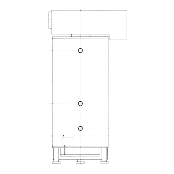
- Page 27 Figure No. 9 - Boiler Dimensions/Clearances. NOTE! The 533 centres relates to boilers close coupled in modular form. For stand-alone applications a minimum of 150mm should be allowed between casings. (Space baskets 200mm apart). HAMWORTHY HEATING LTD. PUREWELL PERMANENT IGNITION 500001045/F...
- Page 28 Figure No. 10 - General Layout (Front View). HAMWORTHY HEATING LTD. PUREWELL PERMANENT IGNITION 500001045/F...
- Page 29 This table must be used in conjunction with losses of various fittings fitted in the gas line shown below. For example: - 2 Purewell 120kW Boilers being fed by 2 ” pipe with 6 elbows between gas meter and boiler header can have a maximum length of 72m - (6 x 2m) = 60 metres run to achieve a 1mbar loss.
- Page 30 Figure No. 12 - Purewell Boiler Site Wiring Diagram (Permanent Pilot). NOTE!..Maximum rating of a volt free contact(s) is : 3 Amperes Resistive WARNING! External voltage MUST NOT be applied to remote stop/start terminals 3 & 4 or high/low control loop terminals C3 & C4 or any terminals on the fascia.
- Page 31 Figure No. 13 - Standard Controls Wiring Diagram Schematic. HAMWORTHY HEATING LTD. PUREWELL PERMANENT IGNITION 500001045/F...
- Page 32 Figure No. 14 - Permanent Pilot Wiring Schematic (Pilot-stat operation) HAMWORTHY HEATING LTD. PUREWELL PERMANENT IGNITION 500001045/F...
- Page 33 Figure No. 15 - Diagram of Igniter Assembly (Permanent Pilot) HAMWORTHY HEATING LTD. PUREWELL PERMANENT IGNITION 500001045/F...
- Page 34 Figure No. 16 - Various Gas Valves Fitted to Purewell Boilers a - Honeywell V4400 Series b - Honeywell V4600 Series c - Robertshaw 7000 Series d - SIT NOVA Series HAMWORTHY HEATING LTD. PUREWELL PERMANENT IGNITION 500001045/F...
- Page 35 Tighten the locking nut (if fitted) on the throttle ad- juster screw. Turn the pressure regulator screw anti-clockwise to fine trim the pressure. Refer to Figure No. 16 for type of valve fitted. NOTE! Honeywell valves shown in diagram. HAMWORTHY HEATING LTD. PUREWELL PERMANENT IGNITION 500001045/F...
- Page 36 Figure No. 18 – Fault-Finding Procedures (Permanent Pilot Only) HAMWORTHY HEATING LTD. PUREWELL PERMANENT IGNITION 500001045/F...
- Page 37 Figure No. 18a – Fault-Finding Procedures (Permanent Pilot Only) (Continued) HAMWORTHY HEATING LTD. PUREWELL PERMANENT IGNITION 500001045/F...
-
Page 38: Appendix 'A' - Information Relating To Propane Firing
IT IS ALSO IMPORTANT THAT THE SPACE HOUSING THE BOILER IS ADEQUATELY VENTILATED AT HIGH AND LOW LEVEL. REFER TO MAIN INSTALLER’S GUIDE. 1.0 INTRODUCTION Performance and General Data Information table be- The operation of the Purewell range of boilers on LPG- low. Propane (3 family)I... - Page 39 Seal the ad- juster after setting. Key: I - Gas Pressure Switch 15.0 RECOMMENDED SPARES II - Main Gas Valves MECHANICAL ITEMS PART No. Pilot Injector - Propane......331101850 (marked 0.23P) Low Gas Pressure Switch....339009477 HAMWORTHY HEATING LTD. PUREWELL PERMANENT IGNITION 500001045/F...
- Page 40 THIS PAGE LEFT INTENTIONALLY BLANK HAMWORTHY HEATING LTD. PUREWELL PERMANENT IGNITION 500001045/F...
- Page 41 Tyne & Wear NE33 2QH Tel: 003531 830 1211 Tel: 0191 455 7898 Fax: 003531 830 1990 Fax: 0191 455 7899 For all other areas, or for further advice, please contact Hamworthy Heating head office service department in Poole, telephone 01202 662500.
- Page 42 DELIVERY ENQUIRIES ......... 01202 662515/662504 Deliveries from Hamworthy Heating arrive direct from the factory on a vehicle equipped with a tail-lift for ease of off-loading to ground level. Our contracts team will progress despatch and liaise individual delivery arrangements. SPARE PARTS ............
Need help?
Do you have a question about the Purewell and is the answer not in the manual?
Questions and answers