MicroNet SP916NL User Manual
150mbps wireless broadband router
Hide thumbs
Also See for SP916NL:
- User manual (81 pages) ,
- Quick installation manual (2 pages) ,
- Quick installation manual (2 pages)
Table of Contents
Advertisement
Quick Links
Advertisement
Table of Contents

Subscribe to Our Youtube Channel
Related Manuals for MicroNet SP916NL


Summary of Contents for MicroNet SP916NL
- Page 1 150Mbps Wireless Broad- band Router User’s Manual Model No.: SP916NL...
-
Page 2: Table Of Contents
Contents 3 HOW TO CONFIGURE TO ACCESS THE INTERNET ..................15 3.1 H ....... 15 OW TO ET THE ETWORK ONFIGURATIONS 3.2 L ............19 OG IN TO THE OUTER 3.3 F ............20 NTERNET CCESS 3.4 F .............. 21 NCRYPTION 4 ADVANCED SETTINGS .......... - Page 3 6.1 DHCP S ..............45 ERVER 6.2 DHCP C ............45 LIENT 7 VIRTUAL SERVER ............. 47 7.1 P ..........47 ANGE ORWARDING 7.2 DMZ S ..............50 ETTINGS 7.3 UPNP S ............... 50 ETTINGS 8 SECURITY SETTINGS ..........52 8.1 C ............
- Page 4 APPENDIX 3 FAQ ............69 APPENDIX 4 CLEAR WIRELESS CONFIGURATION . 71 APPENDIX 5 REGULATORY INFORMATION ....75...
-
Page 5: Package Contents
1 Introduction Micronet SP916NL is an 11n Wireless Broadband Router. It is compliant with IEEE 802.11n and backward compatible with IEEE 802.11b/g. It provides a better wireless signal for network than existing wireless 802.11g technology. Package contents Prior to the installation of the device, please verify the... -
Page 6: Product Features
Product Features Includes router, wireless access point, four-port switch and firewall in one Complies with the latest IEEE802.11n standard and IEEE802.11 b/g standards Increases 6 times coverage distance than 802.11g standard and reduces the dead spots in the cover- age area Supports transmitting rate 3 times than wireless G- ... - Page 7 Supports auto negotiation/manual mode for 802.11b/802.11g Supports UPnP and DDNS Supports LAN access control to the Internet Supports virtual server, DMZ host Supports WDS wireless network extension Supports broadband control function ...
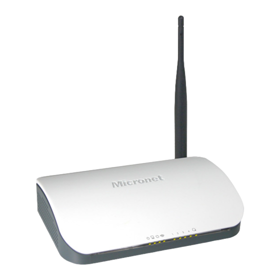
- Page 8 1.3 LED Indicator and Port Description Front Panel and LED Indicator Show LED indicator description on front panel: POWER When turns green, Always ON indicates the power connects well. When turns green, blinking indicates the system runs...
- Page 9 well. When blinking, it indicates the device is negotiating with client in WPS mode. WLAN Wireless signal LED indicator. When turns green, blinking indicates the wireless function is enabled. LAN (1,2,3,4) Wired local network LED indicator. Always ON indicates it is connected with Ethernet device; blinking indicates the device is transmitting and/or receiving data.
- Page 10 Back Panel Show: Rear Panel: POWER The jack is for power adapter connection. Please use the included 9V DC power adapter. A 100Mbps Ethernet port can be connected with MODEM, Switch, Router and other Ethernet device for Internet connecting to DSL MODEM, Cable MODEM and ISP.
-
Page 11: Product Installation
2 Product Installation 2.1 Hardware Installation After you unpack the box, please follow the steps below to connect. For better wireless performance, please put the device in the middle of wireless coverage area. 1. Please use the included power adapter to power on the Router. - Page 12 3. Please connect your broadband line provided by your ISP to the WAN port.
-
Page 13: Network Application Plan
2.2 Network Application Plan Usually wireless LAN Network is deployed in a planned environment where each access point is located in a steady place with certain wireless coverage area for communication service. Generally speaking, it is in the center of the area to reduce “dead spot”. - Page 14 3 How to Login to the Router The chapter mainly presents how to enter the Router’s Web page. After you have finished the hardware installation, the following steps will assist you to set the network configurations for you computer. 3.1 How to Set the Network Configurations 1.
- Page 15 2. Right click “Local Area Network Connection” and select “Properties”. 3. Select “Internet Protocol (TCP/IP)” and click “Properties”.
- Page 16 4. Select “Obtain an IP address automatically” and “Obtain DNS server address automatically”. Click “OK” to save the configurations. Or select “Use the following IP address” and enter the IP address, Subnet mask, Default gateway as follows: IP Address: 192.168.1.XXX: (XXX is a number from 2~254) Subnet Mask: 255.255.255.0 Gateway: 192.168.1.1 Certainly you need to input the DNS server address provided...
- Page 17 3.2 Login to the Router 1. To access the Router’s Web-based interface, launch a web browser such as Internet Explorer or Firefox and enter the Router’s default IP address, http://192.168.1.1. Press “Enter”. 2. Input the “1234” in Password. Click “OK”. A.
- Page 18 3. If you enter the correct password, the screen will be the next one.
-
Page 19: How To Configure To Access The Internet
3 How to configure to access the Internet 3.1 How to Set the Network Configurations Network Configurations under windows XP 1. Right click “My Network Places” on your computer desktop and select “Properties”. Right click “Local Area Connection” and select “Properties”. Select “Internet Protocol (TCP/IP)”... - Page 20 4. Select “Obtain an IP address automatically” and “Obtain DNS server address automatically”. Click “OK” to save the configurations. Or select “Use the following IP address” and enter the IP address, Subnet mask, Default gateway as follows: IP Address: 192.168.1.XXX: (XXX is a number from 2~254) ...
- Page 21 your ISP. Otherwise, you can enter 168.95.1.1. Click “OK” to save the configurations. Network Configurations under windows 7 1. Click the network icon on the lower right corner of your computer desktop, and then click” Open Network and Sharing Center”. 2.
- Page 22 4. Double click” Internet Protocol Version 4(TCP/IPv4)". 5. Select “Obtain an IP address automatically” and “Obtain DNS server address automatically”. Click “OK” to save the configurations.
-
Page 23: Log In To The Router
Or select “Use the following IP address” and enter the IP address, Subnet mask, Default gateway as follows: IP Address: 192.168.1.XXX: (XXX is a number from 2~254) Subnet Mask: 255.255.255.0 Gateway: 192.168.1.1 DNS server: You should input the DNS server address provided by your ISP. -
Page 24: Fast Internet Access
3.3 Fast Internet Access Two kinds of fast access methods are provided on the router’s web-based utility: ADSL dial-up and DHCP. If you select ADSL dial-up, you only need to enter the access account and access password as well as the wireless password, and then click “Ok” to complete the settings. -
Page 25: Fast Encryption
The default access method is ADSL dial-up and the access account and access password are the same as the ADSL dial-up account and password, which you can inquire your broadband ISP. For other access methods, please refer to WAN settings in chapter 4.The wireless password can only consist of 8 characters, the default is 12345678 and you can modify it when necessary. - Page 26 NOTE: The wireless password can only be 8 characters in length and the default is 12345678, you can modify it when necessary.
-
Page 27: Advanced Settings
4 Advanced Settings 4.1 System Status System status screen allows you to view the router’s WAN port status and system status. Connection status: It displays the router’s WAN connection status. Disconnected: It indicates the router’s WAN port hasn’t been connected with the network cable. -
Page 28: Wan Settings
Connection type: It displays your current access method. LAN MAC address:It displays the Router’s LAN MAC address. WAN MAC address:It displays the Router’s WAN MAC Address. System time:It displays the system’s updated time Connected client : It displays the number of the connected com- puters(normally it displays the number of clients whose IP addresses obtained via DHCP server) ... - Page 29 Mode: Show your current connection mode. Access Account: Enter the account provided by your ISP. Access Password: Enter the password provided by your ISP. MTU: Maximum Transmission Unit. It is the size of the largest data packet that can be sent over the network.
- Page 30 be elapsed before you are disconnected from the Internet. Connect Manually: Connect to the Internet by users manually. Connect on Fixed Time: Connect to the Internet during the time you fix automatically. NOTE: The “Connect on Fixed Time” goes into effect only when you have set the current time in “Time settings”...
-
Page 31: Lan Settings
in this mode, just Click “Ok” to finish the settings. 4.3 LAN Settings Click “Advanced settings” –LAN settings to enter the following screen. LAN MAC address: The Router’s LAN MAC address, which is unchangeable. IP address: The Router’s LAN IP address (not your PC’s IP address).The default value is 192.168.1.1;... -
Page 32: Wan Medium Type
DNS setting: Select to enable the DNS server. Primary DNS address: Enter the necessary address provided by your ISP. Alternate DNS address: Enter the second DNS address if your ISP provides, which is optional. NOTE: After the settings are completed, reboot the device to activate the modified settings. -
Page 33: Mac Clone
Wired WAN is the default mode. Wireless WAN: Enable this mode if your ISP provides you wireless connection service or you want to use it to amplify wireless signals. SSID: SSID (Service Set Identifier) is the identity of the wireless device. You can only access to the ISP’... -
Page 34: Bandwidth Control
MAC Address clone: Some Internet service providers require end-user's MAC address to access their network. This feature copies the MAC address of your network device to the router. MAC Address: The MAC address to be registered with your Internet service provider. Restore Default MAC: Restore the default hardware MAC address. - Page 35 IP Address: The IP address range of the hosts whose traffic has been controlled. It can be a single IP address or IP address range. Upload/Download: To specify the traffic heading way for the selected IP addresses: upload or download. ...
- Page 36 And then add a download rule as shown in the picture below. The setting method is the same as the above. Example 2 Set the download rate of all computers within the range of 192.168.1.2--192.168.1.254 as 100-120KByte/s, and the upload rate as 20-30KByte/s, as shown in the picture below.
-
Page 37: Traffic Statistics
The setting method is the same as Example 1. 4.8 Traffic Statistics Traffic statistics is used to display the bandwidth that LAN PC used. Enable Traffic statistics: It is used to calculate the traffic used by the LAN computers. You can enable it to calculate the traffic for you. Usually, disable it to improve the router’s data packet processing ability, and the default is disabled. - Page 38 Sent message: the number of the calculated computer’s data packets that are sent out through the router. Sent Bytes: the volume of the calculated computer’s statistics that is sent out through the router Received message: the number of the calculated computer’s the data packets that are received through the router.
-
Page 39: Wlan Settings
5 WLAN Settings 5.1 Wireless Basic Settings Enable wireless function: Select to enable the Router’s wireless features; deselect to disable it and all functions related with wireless are disabled. Wireless working mode: This router provides two kinds of working modes: Wireless Access Point(AP) and Network Bridge (WDS) Wireless Access Point (AP) ... - Page 40 network. 11b/g mixed mode: Select it if you have only Wireless-B and Wireless-G clients in your network. 11b/g/n mixed mode: Select it if you have Wireless-B, Wireless-G Wireless-N clients your network. SSID: It is the unique name of the wireless network and can be modified.
- Page 41 Network Bridge (WDS) Settings WDS (Wireless Distribution System) is used to expand wireless coverage area.
- Page 42 AP MAC address: Input the MAC address of another (opposing) wireless router you want to connect. Example: This example is to bridge two SP916NL routers. 1. If you know the connecting router’s MAC address, please enter it into the AP MAC address field and click “Ok”.
-
Page 43: Wireless Security Settings
Click “Ok” after the MAC address is added. After finishing the above steps, you need to set the other SP916NL router in the same way. NOTE: WDS feature requires both routers support this function and the SSID, channel, encryption method and password are the same as those of the connecting router. -
Page 44: Wps Settings
With the wireless security function, you can prevent others from connecting to your wireless network and using the network resources without your consent. Meanwhile, you can also block illegal users from intercepting or intruding your wireless network. 5.2.1 WPS Settings WPS (Wi-Fi Protected Setting) makes it quick and easy to establish a secure connection between the wireless clients and the router. -
Page 45: Wpa- Psk
WPS is enabled. During this time (flashing WPS LED), you can enable the wireless client to implement the WPS/PBC negotiation between them. When the WPS connection is completed, the LED indicator will be continuously lit. To add more clients, repeat the above steps.) ... -
Page 46: Wpa2- Psk
WPA Algorithms: Provides TKIP [Temporal Key Integrity Protocol] or AES [Advanced Encryption Standard]. Key: Enter the pass phrase that consists of 8-63 ASCII characters. Key Renewal Interval: Set the key’s renewal period, which tells the device how often it should change the dynamic keys. 5.2.3 WPA2- PSK WPA2 (Wi-Fi Protected Access version 2) provides higher security than and WPA (Wi-Fi Protected Access). -
Page 47: Wireless Access Control
WPA Algorithms: Provides TKIP [Temporal Key Integrity Protocol] or AES [Advanced Encryption Standard]. Key: Enter the pass phrase that consists of 8-63 ASCII characters. Key Renewal Interval: Set the key’s renewal period, which tells the device how often it should change the dynamic keys. 5.3 Wireless Access Control Wireless access control is actually based on the MAC address to permit or forbid specific clients to access the wireless network. -
Page 48: Connection Status
MAC address filter: “Permit” indicates to allow the clients in the list to access the wireless network, “Forbid” indicates to prevent the clients in the list from accessing the wireless network. Configure MAC address: Input the MAC addresses of the wireless clients to implement the filter policy. -
Page 49: Dhcp Server
6 DHCP Server 6.1 DHCP Server DHCP (Dynamic Host Control Protocol) is used to assign an IP address to the computers on the LAN/private network. When you enable the DHCP Server, the DHCP Server will allocate automatically an unused IP address from the IP address pool to the requesting computer in premise of activating “Obtain an IP Address Automatically”. - Page 50 Host name: It displays the name of the computer whose IP is allocated by the DHCP server. IP address: Enter the IP address which needs static binding. MAC address: Enter the MAC address of the computer you want to bind.
-
Page 51: Virtual Server
7 Virtual Server 7.1 Port Range Forwarding Start/End port: Enter the start/end port number which ranges the External ports used to set the server or Internet applications. LAN IP: Enter the IP address of the PC which you want to set as the server. - Page 52 the ID drop-down list and then click “Add”, this port will be added automatically to the ID list. For other well known service ports that are not listed, you can manually add them to the list. Add to: Add the selected well-known port to the policy ID. For Example: You want to share some large files with your friends outside of your local area network, however, they are too big, and it’s not convenient to transfer them.
- Page 53 4. Click the “Ok” button to save the settings. And now, when your friends want to visit the FTP server, they only need to enter ftp://xxx.xxx.xxx.xxx:21 in the address field. Here, xxx.xxx.xxx.xxx means the router’s WAN IP address. For example, when your router’s WAN IP address is 210.242.6.221;...
-
Page 54: Dmz Settings
7.2 DMZ Settings The DMZ Settings screen allows one local computer to be exposed to the Internet for use of a special-purpose service such as Internet gaming or videoconferencing. DMZ hosting forwards all the ports at the same time to one PC. - Page 55 Enable UPnP: Click the checkbox to enable the UPnP. NOTE: This function goes into effect under Windows XP or Windows ME (NOTE: the system should integrate or have installed the Directx 9.0) or this function would go into effect if you have installed software that supports UPnP.
-
Page 56: Security Settings
8 Security Settings 8.1 Client Filter Settings You can enable client filter to control LAN computers’ access to some ports of the Internet: Filter Mode: You can select either “Permit only” or “Forbid only”. Access Policy: Select one number from the drop-down list. ... -
Page 57: Ddress Filter
Example 2 Permit LAN computer with the IP address of 192.168.1.145 to access websites during 8:00 to 18:00 from Sunday to Saturday. 8.2 MAC Address Filter You can limit the computer’s access to Internet by MAC Address Filter. -
Page 58: Url Filter Settings
Filter mode: You can select either “Permit only” or “Forbid only”. Access Policy: Select one number from the drop-down list. Remark: A simple description of the configured file. You can also leave it blank. MAC Address: Enter the MAC address you want to run the access policy. -
Page 59: Remote Web Management
Filter Mode: You can select either “Permit only” or “Forbid only”. Access Policy: Select one number from the drop-down list. Remark: A simple description of the configured file. You can also leave it blank. Start/End IP: Enter the start/end IP address. ... - Page 60 This section instructs how to allow the network administrator to manage the Router remotely. If you want to access the Router from outside of the local network, please click the checkbox after “Enable”. Enable: Check to enable remote web management. ...
-
Page 61: Routing Settings
9 Routing Settings 9.1 Routing Table This page shows the router’s core routing table. The main duty for a router is to look for a best path for every data packet, and transfer this data packet to a destination station. In order to fulfill this function, many transferring paths, i.e. - Page 62 Gateway: The entry IP address of the next router. NOTE: 1. The gateway must be at the same net segment with the router’s LAN IP. 2. If the destination IP address is a host address, then the subnet mask must be 255.255.255.255.
-
Page 63: System Tools
10 System Tools 10.1 Time Settings This section is to configure the router’s system time. You can set it manually or obtain the GMT time from the Internet. Time zone: Select the time zone where you are operating the Router from the drop-down list. - Page 64 3322.org as follows: Username Micronet Password 123456 Domain Name Micronet.3322.org After mapping the port in the virtual server, and setting account information in DDNS server, you can then access the web page by entering http:// micronet.3322 .org in the address field.
-
Page 65: Backup/Restore
10.3 Backup/Restore On this screen, you can back up the router’s current settings or restore previous settings. Backup Setting: Click the Backup button to back up the Router’s settings and select a path to save them. Click the “Save” button to save the configuration files. Restore Setting: ... -
Page 66: Restore To Factory Default
Click the “Restore” button to restore previous settings. 10.4 Restore to Factory Default This screen allows you to restore all settings to the factory default values. Restore: Click this button to restore to default settings. Factory default settings: Password: 1234(the default password displays as null) IP address: 192.168.1.1 Subnet mask: 255.255.255.0... -
Page 67: Upgrade
10.5 Upgrade By upgrading the router’s software, you’ll get better software version and appreciated routing function. Before upgrading, download the Router’s software upgrade file from our website, www. micronet.info Browse: Click this button to select the upgrade file. ... -
Page 68: Password Change
10.7 Password Change This section is to set a new password to better secure your router and network. Old password: Enter the old password. New password: Enter a new password. Confirm new password: Re-enter to confirm the new password. NOTE: The default password displays as null, users can log on the web-based utility without any authentication. -
Page 69: Log Out
Refresh: Click this button to update the log. Clear: Click this button to clear the current shown log. 10.9 Log out After all settings are finished, please click’” Log out” to exit securely and completely. -
Page 71: Appendix 1 Glossary
Appendix 1 Glossary Channel: An instance of medium use for the purpose of passing protocol data units (PDUs) that may be used simultaneously, in the same volume of space, with other instances of medium use(on other channels) by other instances of the same physical layer (PHY),with an acceptably low frame error ratio(FER) due to mutual interference. -
Page 72: Appendix 2 Product Features
being decrypted. To solve the publishing problem for digital certification, people make some changes to TLS authentication and TTLS and EAP come into exist, which enable you to access the network by using the traditional way of authentication: username and password. Appendix 2 Product Features Supports IEEE 802.11n, IEEE 802.11g, IEEE 802.11b, IEEE 802.3 ... -
Page 73: Appendix 3 Faq
If your problem is not in the list, please log into our website www. micronet.info or send an E-mail to www. micronet.info , and we will reply to you at the earliest time. 1. Can not log in to the Web-based Utility of the router after you enter the... - Page 74 What can I Press the “RESET” button for 7 seconds to restore the Router to default settings. 3. The computer connected with the Router shows IP address conflict. What can Check if there are other DHCP servers in the LAN and if there are then disable them.
-
Page 75: Appendix 4 Clear Wireless Configuration
service ports: Server Protocol Service Port WEB Server FTP Server Telnet NetMeeting 1503:1720 File Send:6891-6900(TCP) MSN Messenge TCP/UDP Voice:1863:6901(TCP) Voice:1863:5190(UDP) PPTP VPN 1723 Iphone5.0 22555 SMTP POP3 Appendix 4 Clear Wireless Configuration Clear Wireless configuration file under windows XP 1. Right click “My Network Places” on your computer desktop and select “Properties”. - Page 76 2. Right click “Wireless Network Connections” and select “Properties”. 3. Click “Wireless Network Configuration” and clear the corresponding wireless configuration file as shown below.
- Page 77 Clear Wireless configuration file under windows 7 1. Right click “Network” and click “Properties”. 2. Click “Manage wireless networks” on the left side of the window.
- Page 78 3. Delete the corresponding configured file in the “Manage wireless networks”.
-
Page 79: Appendix 5 Regulatory Information
Appendix 5 Regulatory Information EU Declaration or Declaration of Conformity Hereby, Micronet Communication Inc., declares that this Wireless Broad- band Router is in compliance with the essential requirements and other rel- evant provisions of Directive 1999/5/EC. FCC Statement This equipment has been tested and found to comply with the limits for a Class B digital device, pursuant to part 15 of the FCC rules. - Page 80 1) This device may not cause interference, and 2) This device must accept any interference, including interference that may cause undesired operation of the device. Caution! The manufacturer is not responsible for any radio or TV interference caused by unauthorized modifications to this equipment. Such modifica- tions could void the user authority to operate the equipment.
Need help?
Do you have a question about the SP916NL and is the answer not in the manual?
Questions and answers