
Related Manuals for Midea Vertu series


Summary of Contents for Midea Vertu series
-
Page 1: Service Manual
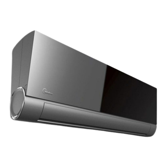
VSI-1104-A SERVICE MANUAL MIDEA AIRCONDITIONER DC INVERTER SPLIT WALL-MOUNTED TYPE Vertu SERIES... -
Page 2: Table Of Contents
CONTENTS 1. Precaution ..............................1 1.1 Safety Precaution ........................1 1.2 Warning ............................1 2. Function ................................ 6 3. Dimension ..............................9 3.1 Indoor Unit ........................... 9 3.2 Outdoor Unit ..........................10 4. Refrigerant Cycle Diagram ........................11 5. -
Page 3: Precaution
1. Precaution 1.1 Safety Precaution To prevent injury to the user or other people and property damage, the following instructions must be followed. Incorrect operation due to ignoring instruction will cause harm or damage. Before service unit, be sure to read this service manual at first. 1.2 Warning ... - Page 4 Sharp edges could cause injury, be especially careful of the case edges and the fins on the condenser and evaporator. For installation, always contact the dealer or an Authorized service center. There is risk of fire, electric shock, explosion, or injury. ...
- Page 5 Do not use the telephone or turn switches on or off. There is risk of explosion or fire. If strange sounds, or small or smoke comes from product. Turn the breaker off or disconnect the power supply cable. There is risk of electric shock or fire. ...
- Page 6 A bad connection may cause water leakage. Keep level even when installing the product. To avoid vibration of water leakage. Do not install the product where the noise or hot air from the outdoor unit could damage the neighborhoods. It may cause a problem for your neighbors.
- Page 7 A dirty filter reduces the efficiency of the air conditioner and could cause product malfunction or damage. Do not insert hands or other object through air inlet or outlet while the product is operated. There are sharp and moving parts that could cause personal injury. ...
-
Page 8: Function
2. Function Model List Indoor units Outdoor units MSV1-18HRDN1-QC2F(D) MOC2-18HDN1-QC2 MSV1-24HRDN1-QC2W MOF-24HDN1-QC2W MSV1-18HRDN1-QC2F(E) MOC2-18HDN1-QC2 MSV1-09HRDN1-QC2 MOR-09HDN1-QC2 MSV1-12HRDN1-QC2 MOR-12HDN1-QC2 MSV1-09HRFN1-ND2E MOC-09HDN1-ND2E MSV1-12HRFN1-ND0E MOC1-12HFN1-ND0E MSV1-09HRDN1-QC8 MOC-09HDN1-QC8 MSV1-12HRDN1-QC4 MOC-12HDN1-QC4 MSV1-09HRDN1-QC2(D) MOA-09HDN1-QC2 MSV1-12HRDN1-QC2(D) MOB4-12HDN1-QC2... - Page 9 Indoor unit Operation by remote controller Sensing by room temperature Room temperature sensor. Pipe temperature sensor. Room temperature control Maintain the room temperature in accordance with the setting temperature. Indoor golden fin Anti-freezing control in cooling Prevent the water being frozen on evaporator by sensing the evaporator pipe temperature in cooling Ionizer mode...
- Page 10 Outdoor unit Power relay control The unit has 3 minutes delay between continuously ON/OFF operations. Low noise air flow system Bird tail propeller fan makes the outdoor unit run more quietly. Hydrophilic aluminum fin The hydrophilic fin can improve the heating efficiency at operation mode.
-
Page 11: Dimension
3. Dimension 3.1 Indoor Unit Dimension (mm) Model MSV1-09HRDN1-QC2 MSV1-09HRDN1-QC2(D) MSV1-12HRDN1-QC2 MSV1-09HRFN1-ND2E MSV1-12HRFN1-ND0E MSV1-09HRDN1-QC8 MSV1-12HRDN1-QC4 MSV1-12HRDN1-QC2(D) MSV1-18HRDN1-QC2F(D) MSV1-18HRDN1-QC2F(E) MSV1-24HRDN1-QC2W 1080... -
Page 12: Outdoor Unit
3.2 Outdoor Unit Dimension (mm) Model MOR-09HDN1-QC2 MOR-12HDN1-QC2 MOC2-18HDN1-QC2 MOC-09HDN1-ND2E MOC1-12HFN1-ND0E MOC-12HDN1-QC4 MOC-09HDN1-QC8 MOF-24HDN1-QC2W MOA-09HDN1-QC2 MOB4-12HDN1-QC2... -
Page 13: Refrigerant Cycle Diagram
4. Refrigerant Cycle Diagram... -
Page 14: Wiring Diagram
5. Wiring Diagram 5.1 Indoor Unit MSV1-09HRDN1-QC2 MSV1-12HRDN1-QC2 MSV1-18HRDN1-QC2F(D) MSV1-09HRDN1-QC8 MSV1-12HRDN1-QC4 MSV1-09HRDN1-QC2(D) MSV1-12HRDN1-QC2(D) - Page 15 MSV1-24HRDN1-QC2W MSV1-18HRDN1-QC2F(E)
- Page 16 MSV1-09HRFN1-ND2E MSV1-12HRFN1-ND0E...
-
Page 17: Outdoor Unit
5.2 Outdoor Unit MOR-09HDN1-QC2 MOR-12HDN1-QC2... - Page 18 MOC2-18HDN1-QC2 MOF-24HDN1-QC2W...
- Page 19 MOC2-18HDN1-QC2...
- Page 20 MOC-09HDN1-ND2E MOC1-12HFN1-ND0E...
- Page 21 MOC-09HDN1-QC8 MOC-12HDN1-QC4...
- Page 22 MOA-09HDN1-QC2 MOB4-12HDN1-QC2...
-
Page 23: Installation Details
6. Installation details 6.1 Wrench torque sheet for installation Additional tightening Outside diameter Torque torque N.cm inch N.cm 1570 1960 Ф6.35 (160kgf.cm) (200kgf.cm) 2940 3430 Ф9.53 (300kgf.cm) (350kgf.cm) 4900 5390 Ф12.7 (500kgf.cm) (550kgf.cm) 7360 7850 Ф16 (750kgf.cm) (750kgf.cm) 6.2 Connecting the cables he power cord of connect should be selected according to the following specifications sheet. -
Page 24: Pipe Length And The Elevation
6.3 Pipe length and the elevation Pipe size Standard Max. Max. Additional Capacity length Elevation Length refrigerant Btu/h Liquid B (m) A (m) (g/m) MSV1-09HRDN1-QC2 MSV1-12HRDN1-QC2 4/8’’ 3/8’’ MSV1-09HRFN1-ND2E (Ф6.35) (Ф9.53) MSV1-09HRDN1-QC8 MSV1-09HRDN1-QC2(D) MSV1-18HRDN1-QC2F(E) 1/2’’ 4/8’’ MSV1-18HRDN1-QC2FD (Ф12.7) (Ф6.35) MSV1-12HRFN1-ND0E 1/2’’... -
Page 25: Air Purging With Vacuum Pump
6.4 Air purging with vacuum pump Air and moisture in the refrigerant system have undesirable effects as below: ● Pressure in the system rises. ● Operating current rises. ● Cooling or heating efficiency drops. ● Moisture in the refrigerant circuit may freeze and block capillary tubing. ●... -
Page 26: Pumping Down (Re-Installation)
operation of the vacuum pump. Make evacuation for 15 minutes or more and check the compound meter indicates -76cmHg. 6. Turn the stem of the Hi valve about 45°counterclockwise for 6 or 7seconds after the gas coming out, then tighten the flare nut again. Make sure the pressure display in the pressure indicator is a little higher than the atmosphere pressure. -
Page 27: Re-Air Purging (Re-Installation)
valve. Connect the charge hose with the push pin to the gas service port. 5. Air purging of the charge hose. Open the low-pressure valve on the charge set slightly to purge air from the charge hose. 6. Set the 2-way valve to the close position. 7. -
Page 28: Balance Refrigerant Of The 2-Way, 3-Way Valves
3. Air purging. Open the valves on the charging cylinder and the charge set. Purge the air by loosening the flare nut on the 2-way valve approximately 45’ for 3 seconds then closing it for 1 minute; repeat 3 times. After purging the air, use a torque wrench to tighten the flare nut to on the 2-way valve. -
Page 29: Evacuation
Procedure: 1. Confirm that both the 2-way and 3-way valves are set to the open position. 2. Connect the charge set to the 3-way valve’s service port. Leave the valve on the charge set closed. Connect the charge hose with the push pin to the service port. 3. -
Page 30: Gas Charging
4. Disconnect the charge hose from the vacuum pump. 6.9 Gas charging Procedure: 1. Connect the charge hose to the charging cylinder. Connect the charge hose which you disconnected from the vacuum pump to the valve at the bottom of the cylinder. -
Page 31: Operation Characteristics
7. Operation characteristics Mode Dehumidify Cooling operation Heating operation Temperature operation ≥17 ≤ 30 Room temperature ﹥10℃ Outdoor temperature 0℃~50℃ -15℃~34℃ 0℃~ 50℃ CAUTION: 1. If air conditioner is used beyond the above conditions, the certain protections may action. 2. Room relative humidity should be less than 80%. If the air conditioner operates in excess of this value, the surface of the air conditioner may attract condensation. -
Page 32: Electronic Function
8. Electronic function 8.1 Abbreviation T1: Indoor ambient temperature T2: Pipe temperature of indoor heat exchanger T3: Pipe temperature of outdoor heat exchanger T4: Outdoor ambient temperature T5: Discharge temperature 8.2 Display function 8.2.1 Icon explanation on indoor display board. TIMER display Illuminated during Timer operation. -
Page 33: Main Protection
8.3 Main Protection 8.3.1 Three Minutes Delay at restart for compressor. ---- 1min delay for the 1 time start-up and 3 minutes delay for others. 8.3.2 Temperature protection of compressor top. ---- Top temp. protector cut off for 30s and restart the compressor with 3 minutes delay. 8.3.3 Temperature protection of compressor discharge. -
Page 34: Operation Modes And Functions
----Preheating release condition: If T4>5 or user turns on the machine and compressor runs, preheating function will stop. ---- Crankcase Heater It starts when T4<5 and stops when T4>15 8.4 Operation Modes and Functions 8.4.1 Fan only mode. (1) Outdoor fan and compressor stop. (2) Temperature setting function is disabled, and no setting temperature is displayed. - Page 35 If users switch on A/C by remote controller, the compressor will run at the Fmax frequency for 7 minutes according to outdoor ambient temp. During the 7 minutes, frequency limitation is active. 7 minutes later, the compressor running frequency will be controlled as below: While Temp.zone Frequency...
- Page 36 If the current increased more than I2COOL, the frequency will decrease automatically, if the current raise to over I3COOL, the compressor will stop and restart 3min later. During the frequency decreasing, if the current deceased to between I1COOL and I2COOL, the frequency will hold.
- Page 37 8.4.2.3 Indoor fan running rules In cooling mode, indoor fan runs all the time and the speed can be selected as high, medium, low and auto. Auto fan in cooling mode acts as follow: 8.4.2.4 Condenser high temperature T3 protection. When 55 <T3<60 , the compressor frequency will decrease to the lower level every 3 min until to F1 and then run at F1.
- Page 38 8.4.3 Heating Mode 8.4.3.1 Compressor running rules: The operation frequency of compressor after starting submits to following rule. After A/C starts up, the compressor will run at the Fmax frequency for 7 minutes according to outdoor ambient temp. During the 7 minutes, frequency limitation is active. 7 minutes later, compressor running frequency will be controlled as below:...
- Page 39 While Temp. zone Frequency ∆T=0 as default. Note: When T1-Ts keeps in the same temp. zone for 3 minutes, the compressor will run as the below rules: A~E: Increase the frequency to the higher level until to F10. F: Keep the current frequency. G: Decrease the frequency to the lower level until to F1.
- Page 40 If the current deceased to lower than I1HEAT, the frequency limit will be invalid. Current Model I1HEAT I2HEAT I3HEAT MSV1-09HRDN1-QC2+ MOR-09HDN1-QC2 MSV1-12HRDN1-QC2+MOR-12HDN1-QC2 MSV1-18HRDN1-QC2F(D)+ MOC2-18HDN1-QC2 MSV1-18HRDN1-QC2F(E)+ MOC2-18HDN1-QC2 MSV1-24HRDN1-QC2W+MOF-24HDN1-QC2W MSV1-09HRFN1-ND2E+ MOC-09HDN1-ND2E MSV1-12HRFN1-ND0E+ MOC1-12HFN1-ND0E MSV1-09HRDN1-QC8+ MOC-09HDN1-QC8 MSV1-12HRDN1-QC4+ MOC-12HDN1-QC4 MSV1-12HRDN1-QC2(D)+ MOB4-12HDN1-QC2 MSV1-09HRDN1-QC2(D)+ MOA-09HDN1-QC2 8.4.3.2 Outdoor fan running rules: Outdoor fan and compressor start up at the same time, outdoor fan stop 30s delay after the compressor stopped.
- Page 41 For 9K,12K,18K units For 24K unit Auto fan action in heating mode. 8.4.3.4 Defrosting mode: Conditions of defrosting: Condition 1: If T4>0 , When the units are running, if any one of the following conditions is satisfied, the unit starts defrosting: ①...
- Page 42 than -4 over 3 minutes. Condition 2: If T4<0 , If satisfied any item of the condition 1 and the T2 temperature has decreased 5 , starts defrosting. Note: T2 is the maximum value of the evaporator temperature during the anti-cold wind function. It’s recorded by the system automatically.
- Page 43 Defrosting action: For MSV1-24HRDN1-QC2W, MSV1-18HRDN1-QC2FD, MSV1-18HRDN1-QC2F(E) Model MSV1-18HRDN1-QC2F(D)+MOC2-18HDN1-QC2 MSV1-18HRDN1-QC2F(E)+ MOC2-18HDN1-QC2 MSV1-24HRDN1-QC2W+MOF-24HDN1-QC2W For MSV1-09HRDN1-QC2, MSV1-12HRDN1-QC2, MSV1-09HRFN1-ND2E, MSV1-12HRFN1-ND0E, MSV1-09HRDN1-QC8, MSV1-12HRDN1-QC4, MSV1-09HRDN1-QC2(D), MSV1-12HRDN1-QC2(D)
- Page 44 8.4.3.5 High evaporator coil temp.T2 protection: (1) T2> TEH2, compressor running frequency decreases to the lower level every 20s. If the frequency decreased to F2 and the T2 still over TEH2 for 3 minutes, the compressor will stop. If T2 deceased to lower than 48 , or 48 <T2<...
- Page 45 8.4.5 Dehumidify mode 8.4.5.1 Indoor fan speed is fixed in breeze and can’t be changed. The louver angle is the same as in cooling mode. 8.4.5.2 Compressor running rules 8.4.5.3 Room over low temperature protection If room temperature is lower than 10 , compressor will stop and not resume until room temperature over 12 .
- Page 46 machine will turn to auto mode as 24 setting temperature. Forced auto mode: The action of forced auto mode is the same as normal auto mode with 24 setting temperature. 8.4.7 Timer function 8.4.7.1 Timing range is 24 hours, and the minimum resolution is 15 minutes. 8.4.7.2 Timer on.
- Page 47 8.4.9 Auto-Restart function The indoor unit is equipped with auto-restart function, which is carried out through an auto-restart module. In case of a sudden power failure, the module memorizes the setting conditions before the power failure. The unit will resume the previous operation setting (not including Swing function) automatically after 3 minutes when power returns.
- Page 48 also turned off.
-
Page 49: Troubleshooting
9. Troubleshooting 9.1 Indoor Unit Error Display Display LED STATUS EEPROM parameter error Indoor / outdoor units communication protection Zero-crossing signal error Indoor fan speed out of control Open or short circuit of outdoor temperature sensor Open or short circuit of room or evaporator temperature sensor Outdoor fan speed out of control IBM malfunction or IGBT over-strong current protection Over voltage or too low voltage protection... -
Page 50: Diagnosis And Solution
9.2 Diagnosis and Solution 9.2.1 EEPROM parameter error diagnosis and solution Shut off the power supply and turn on it 5s later Replace indoor PCB The problem comes out again Is the EEPROM chip plugged in indoor PCB well? Correct the connection Replace the main PCB of indoor unit... - Page 51 9.2.2 Indoor / outdoor units communication protection error diagnosis and solution Turn off the power supply, after 1 minute, connect the power supply , turn on the unit with remote controller The unit does not work normally. Check the wiring between indoor and outdoor unit.
- Page 52 9.2.3 Fan speed out of control diagnosis Shut off the power supply and turn on it 5s later The unit does not work normally Turn off the unit, rotate the cross Disassemble the connection between fan. Does it rotate freely? fan and motor, check if the bearing is normal.
- Page 53 9.2.5 IGBT over-strong current protection diagnosis and solution. Check whether the connections between outdoor PCB and IPM are good? Check whether the IPM is fixed to radiator Fastening the IPM to the radiator tightly The unit does not work normally Replace the compressor Replae the IPM 9.2.6 Over voltage or too low voltage protection diagnosis and solution.
- Page 54 9.2.8 Inverter compressor drive error diagnosis and solution. Is the connection of compressor good? Is the wiring sequence right? The voltage Reconnect and retry range proper? Replace the outdoor PCB Replace inverter compressor. 9.2.9 Zero crossing detection error This is alarm signal when the main chip can’t detect over-zero signal. When such failure occurs, the main control board must have fault.
Need help?
Do you have a question about the Vertu series and is the answer not in the manual?
Questions and answers