HP ProLiant BL460c Gen8 User Manual
Server blade
Hide thumbs
Also See for ProLiant BL460c Gen8:
- Maintenance and service manual (88 pages) ,
- Specifications (58 pages)
Table of Contents
Advertisement
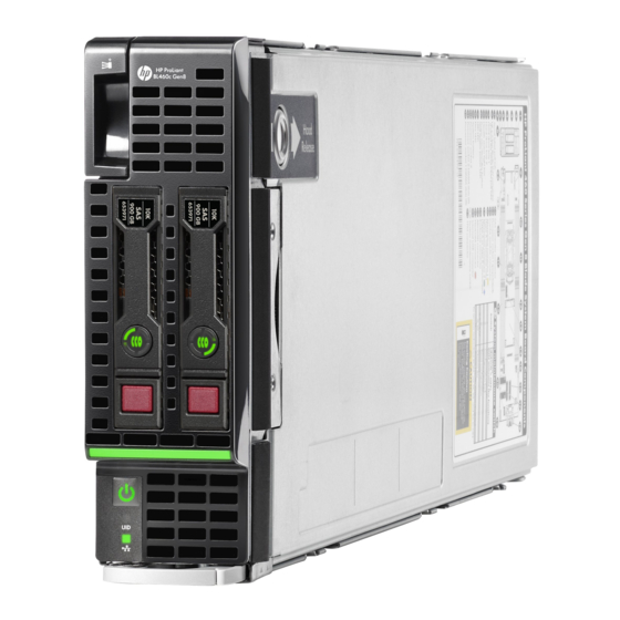
HP ProLiant BL460c Gen8 Server Blade
User Guide
Abstract
This document is for the person who installs, administers, and troubleshoots servers and storage systems. HP assumes you are qualified in the
servicing of computer equipment and trained in recognizing hazards in products with hazardous energy levels.
Part Number: 656396-001
March 2012
Edition: 1
Advertisement
Table of Contents

Related Manuals for HP ProLiant BL460c Gen8


Summary of Contents for HP ProLiant BL460c Gen8
-
Page 1: User Guide
HP ProLiant BL460c Gen8 Server Blade User Guide Abstract This document is for the person who installs, administers, and troubleshoots servers and storage systems. HP assumes you are qualified in the servicing of computer equipment and trained in recognizing hazards in products with hazardous energy levels. - Page 2 Microsoft® and Windows® are U.S. registered trademarks of Microsoft Corporation. Intel® and Xeon® are trademarks of Intel Corporation in the United States and other countries. Bluetooth® is a trademark owned by its proprietor and used by Hewlett-Packard Company under license.
-
Page 3: Table Of Contents
Contents Component identification ....................... 6 Front panel components ..........................6 Front panel LEDs and buttons ......................... 6 Drive LED definitions ............................. 7 System board components ..........................8 System maintenance switch ......................... 8 Mezzanine connector definitions ......................9 DIMM slot locations ..........................9 DIMM tool location .......................... - Page 4 Installing the Trusted Platform Module board ..................40 Retaining the recovery key/password ....................41 Enabling the Trusted Platform Module ....................42 Cabling ............................. 43 Cabling resources ............................43 FBWC capacitor pack cabling........................43 Using the HP c-Class Blade SUV Cable ......................43 Connecting locally to a server blade with video and USB devices ..............
- Page 5 Cables ..............................61 Canadian notice (Avis Canadien) ........................ 61 European Union regulatory notice ........................ 62 Disposal of waste equipment by users in private households in the European Union .......... 62 Japanese notice ............................63 BSMI notice ............................... 63 Korean notice ............................63 Chinese notice ............................
-
Page 6: Component Identification
Component identification Front panel components Item Description Hard drive bay 1 Server blade release button Server blade release lever Hard drive bay 2 HP c-Class Blade SUV connector* (behind the serial label pull tab) Serial label pull tab *The SUV connector and the HP c-Class Blade SUV Cable are used for some server blade configuration and diagnostic procedures. -
Page 7: Drive Led Definitions
Item Description Status Health status LED Solid Green = Normal (System is powered on) Flashing Green = Power On/Standby Button service is being initialized Flashing Amber = Degraded condition Flashing Red = Critical condition Off = Normal (System is in standby) System power LED Solid Green = System is powered on. -
Page 8: System Board Components
System maintenance switch TPM connector The symbols correspond to the symbols located on the interconnect bays. For more information, see the HP ProLiant BL460c Gen8 Server Blade Installation Instructions on the HP website (http://www.hp.com/support). System maintenance switch Position Default Function Off = iLO security is enabled. -
Page 9: Mezzanine Connector Definitions
Position Default Function Off = System configuration can be changed. On = System configuration is locked. Reserved Reserved Off = Power-on password is enabled. On = Power-on password is disabled. Off = No function On = ROM reads system configuration as invalid. -
Page 10: Dimm Tool Location
The arrow points to the front of the server blade. DIMM tool location The DIMM tool is used to open and close an empty DIMM slot. HP c-Class Blade SUV Cable Item Connector Description Server blade For connecting to the SUV connector on the server blade front panel Component identification 10... - Page 11 Item Connector Description Video For connecting a video monitor For connecting up to two USB devices Serial For trained personnel to connect a null modem serial cable and perform advanced diagnostic procedures Component identification 11...
-
Page 12: Operations
Operations Power up the server blade The Onboard Administrator initiates an automatic power-up sequence when the server blade is installed. If the default setting is changed, use one of the following methods to power up the server blade: • Use a virtual power button selection through iLO. •... -
Page 13: Remove The Server Blade
poweroff server [bay number] force This form of the command forces the server blade to enter standby mode without properly exiting applications and the OS. If an application stops responding, this method forces a shutdown. • Use the Onboard Administrator GUI to initiate a shutdown: Select the Enclosure Information tab. -
Page 14: Remove The Access Panel
Remove the access panel To remove the component: Power down the server blade (on page 12). Remove the server blade (on page 13). Press the access panel release button. Slide the access panel towards the rear of the server blade, and then lift to remove the panel. Install the access panel Place the access panel on top of the server blade. - Page 15 Remove the server blade (on page 13). Remove the access panel (on page 14). Disconnect the FBWC battery pack cabling, if connected ("FBWC capacitor pack cabling" on page 43). Remove one or more DIMM baffles. DIMM baffle (left side) DIMM baffle (right side) Operations 15...
-
Page 16: Remove The Sas Controller
Remove the SAS controller Power down the server blade (on page 12). Remove the server blade (on page 13). Remove the access panel (on page 14). Disconnect the FBWC battery pack cabling, if connected ("FBWC capacitor pack cabling" on page 43). - Page 17 Close the SAS controller handle and then install the SAS controller. To properly seat the SAS controller, press firmly in the areas indicated on the SAS controller. Operations 17...
-
Page 18: Setup
Setup Overview Installation of a server blade requires the following steps: Install and configure an HP BladeSystem c-Class enclosure. Install any server blade options. Install interconnect modules in the enclosure. Connect the interconnect modules to the network. Install a server blade. Complete the server blade configuration. -
Page 19: Interconnect Bay Numbering And Device Mapping
Interconnect bay numbering and device mapping • HP BladeSystem c7000 Enclosure To support network connections for specific signals, install an interconnect module in the bay corresponding to the FlexLOM or mezzanine signals. Server blade signal Interconnect bay Interconnect bay labels 1 and 2 FlexLOM 3 and 4... -
Page 20: Connecting To The Network
• HP BladeSystem c3000 Enclosure and Tower Enclosure Server blade signal Interconnect Interconnect Notes bay number bay label — FlexLOM Four port cards connect to bay 2. Mezzanine 1 3 and 4 Mezzanine 2 • Four port cards • Ports 1 and 3 connect to bay 3. •... -
Page 21: Installing A Server Blade
Two types of interconnect modules are available for HP BladeSystem c-Class enclosures: Pass-Thru modules and switch modules. For more information about interconnect module options, see the HP website (http://www.hp.com/go/bladesystem/interconnects). IMPORTANT: To connect to a network with a Pass-Thru module, always connect the Pass-Thru module to a network device that supports Gigabit or 10 Gb speed, depending on the corresponding Pass-Thru model. -
Page 22: Completing The Configuration
Remove the enclosure connector cover. Install the server blade. Completing the configuration To complete the server blade and HP BladeSystem configuration, see the overview card that ships with the enclosure. Setup 22... -
Page 23: Hardware Options Installation
Hardware options installation Introduction If more than one option is being installed, read the installation instructions for all the hardware options and identify similar steps to streamline the installation process. WARNING: To reduce the risk of personal injury from hot surfaces, allow the drives and the internal system components to cool before touching them. -
Page 24: Processor Option
Prepare the drive. Install the drive. Determine the status of the drive from the drive LED definitions (on page 7). Processor option WARNING: To reduce the risk of personal injury from hot surfaces, allow the drives and the internal system components to cool before touching them. CAUTION: To prevent possible server blade malfunction and damage to the equipment, multiprocessor configurations must contain processors with the same part number. - Page 25 Power down the server blade (on page 12). Remove the server blade (on page 13). Remove the access panel (on page 14). Remove the SAS controller (on page 16). Remove the heatsink blank. Retain the heatsink blank for future use. Open each of the processor locking levers in the order indicated, and then open the processor retaining bracket.
- Page 26 Remove the clear processor socket cover. Retain the processor socket cover for future use. Install the processor. Verify that the processor is fully seated in the processor retaining bracket by visually inspecting the processor installation guides on either side of the processor. THE PINS ON THE SYSTEM BOARD ARE VERY FRAGILE AND EASILY DAMAGED.
- Page 27 CAUTION: Do not press down on the processor. Pressing down on the processor may cause damage to the processor socket and the system board. Press only in the area indicated on the processor retaining bracket. Press and hold the processor retaining bracket in place, and then close each processor locking lever. Press only in the area indicated on the processor retaining bracket.
-
Page 28: Memory Options
CAUTION: Heatsink retaining screws should be tightened in diagonally opposite pairs (in an "X" pattern). Install the heatsink. Install the SAS controller (on page 16). Install the access panel (on page 14). Install the server blade ("Installing a server blade" on page 21). Memory options IMPORTANT: This server blade does not support mixing LRDIMMs, RDIMMs, or UDIMMs. -
Page 29: Hp Smartmemory
• Quad-rank PC3L-10600 (DDR3-1333) LRDIMMs, operating as dual-rank DIMMs, at up to 1333 MT/s Speed, voltage, and capacity DIMM type DIMM rank DIMM capacity Native speed (MT/s) Voltage Single-rank 4 GB 1600 RDIMM Dual-rank 8 GB 1333 RDIMM Single-rank 8 GB 1600 RDIMM Dual-rank... -
Page 30: Single-, Dual-, And Quad-Rank Dimms
Channel Slot Slot number For the location of the slot numbers, see "DIMM slot locations (on page 9)." This multi-channel architecture provides enhanced performance in Advanced ECC mode. This architecture also enables the Lockstep memory mode. DIMM slots in this server are identified by number and by letter. Letters identify the population order. Slot numbers indicate the DIMM slot ID for spare replacement. -
Page 31: Dimm Identification
DIMM identification To determine DIMM characteristics, use the label attached to the DIMM and the following illustration and table. Item Description Definition Size — Rank 1R = Single-rank 2R = Dual-rank 4R = Quad-rank Data width x4 = 4-bit x8 = 8-bit Voltage rating L = Low voltage (1.35v) U = Ultra low voltage (1.25v) -
Page 32: Advanced Ecc Memory Configuration
is degrading. This allows DIMMs that have a higher probability of receiving an uncorrectable memory error (which would result in system downtime) to be removed from operation. Advanced Memory Protection options are configured in RBSU. If the requested AMP mode is not supported by the installed DIMM configuration, the server blade boots in Advanced ECC mode. -
Page 33: General Dimm Slot Population Guidelines
Lockstep memory configuration Lockstep mode provides protection against multi-bit memory errors that occur on the same DRAM device. Lockstep mode can correct any single DRAM device failure on x4 and x8 DIMM types. The DIMMs in each channel must have identical HP part numbers. General DIMM slot population guidelines Observe the following guidelines for all AMP modes: •... -
Page 34: Installing A Dimm
Lockstep Memory population guidelines For Lockstep memory mode configurations, observe the following guidelines: • Observe the general DIMM slot population guidelines (on page 33). • DIMM configuration on all channels of a processor must be identical. • In multi-processor configurations, each processor must have a valid Lockstep Memory configuration. •... -
Page 35: Mezzanine Card Option
(on page 8). When installing a mezzanine option on mezzanine connector 2, processor 2 must be installed. For mezzanine card mapping, see the HP ProLiant BL460c Gen8 Server Blade Installation Instructions or see "Interconnect bay numbering and device mapping (on page 19)."... - Page 36 Remove the mezzanine assembly from the server blade. Align the mezzanine card with the guide pins on the mezzanine assembly. Hardware options installation 36...
-
Page 37: Fbwc Capacitor Pack
Install the mezzanine card in the mezzanine assembly, and then tighten the mezzanine card screws to secure the card to the mezzanine assembly. Align the mezzanine assembly with the guide pins on the system board, and then install the mezzanine assembly on the system board. - Page 38 Remove the access panel (on page 14). Install the FBWC capacitor pack: FBWC capacitor pack for the SAS controller FBWC capacitor pack for a mezzanine option. Route the FBWC capacitor pack cable. The DIMM baffles may be removed to route the cables, if necessary.
-
Page 39: Hp Trusted Platform Module Option
Route the cable along the right DIMM baffle and connect the cable to the SAS controller. Route the cable along the left DIMM baffle and connect the cable to the mezzanine option. Install the access panel (on page 14). Install the server blade ("Installing a server blade"... -
Page 40: Installing The Trusted Platform Module Board
• Do not remove an installed TPM. Once installed, the TPM becomes a permanent part of the system board. • When installing or replacing hardware, HP service providers cannot enable the TPM or the encryption technology. For security reasons, only the customer can enable these features. •... -
Page 41: Retaining The Recovery Key/Password
Install the TPM board. Press down on the connector to seat the board ("System board components" on page 8). Install the TPM security rivet by pressing the rivet firmly into the system board. Install the front panel/drive cage assembly. Install the SAS controller (on page 16). Install the DIMM baffle. -
Page 42: Enabling The Trusted Platform Module
To help ensure maximum security, observe the following guidelines when retaining the recovery key/password: • Always store the recovery key/password in multiple locations. • Always store copies of the recovery key/password away from the server blade. • Do not save the recovery key/password on the encrypted hard drive. Enabling the Trusted Platform Module When prompted during the start-up sequence, access RBSU by pressing the F9 key. -
Page 43: Cabling
Cabling Cabling resources Cabling configurations and requirements vary depending on the product and installed options. For more information about product features, specifications, options, configurations, and compatibility, see the QuickSpecs on the HP website (http://h18000.www1.hp.com/products/quickspecs/ProductBulletin.html). At the website, choose the geographic region, and then locate the product by name or product category. FBWC capacitor pack cabling •... -
Page 44: Connecting Locally To A Server Blade With Video And Usb Devices
Connecting locally to a server blade with video and USB devices Use the SUV cable to connect a monitor and any of the following USB devices: • USB hub • USB keyboard • USB mouse • USB CD/DVD-ROM drive Numerous configurations are possible. This section offers two possible configurations. For more information, see "USB support (on page 56)."... -
Page 45: Accessing Local Media Devices
Accessing local media devices Use the following configuration when configuring a server blade or loading software updates and patches from a USB CD/DVD-ROM. Use a USB hub when connecting a USB CD-ROM drive to the server blade. The USB hub provides additional connections. -
Page 46: Troubleshooting
Troubleshooting Troubleshooting resources The HP ProLiant Gen8 Troubleshooting Guide, Volume I: Troubleshooting provides procedures for resolving common problems and comprehensive courses of action for fault isolation and identification, issue resolution, and software maintenance on ProLiant servers and server blades. To view the guide, select a language: •... -
Page 47: Software And Configuration Utilities
Software and configuration utilities Server mode The software and configuration utilities presented in this section operate in online mode, offline mode, or in both modes. Software or configuration utility Server mode Online and Offline HP iLO (on page 47) Online and Offline Active Health System (on page 48) Online and Offline Integrated Management Log (on page 49) -
Page 48: Active Health System
iLO enables and manages the Active Health System (on page 48) and also features Agentless Management. All key internal subsystems are monitored by iLO. SNMP alerts are sent directly by iLO regardless of the host operating system or even if no host operating system is installed. Using iLO, you can do the following: •... -
Page 49: Intelligent Provisioning
The Active Health System log, in conjunction with the system monitoring provided by Agentless Management or SNMP Pass-thru, provides continuous monitoring of hardware and configuration changes, system status, and service alerts for various server components. The Agentless Management Service is available in the SPP, which is a disk image (.iso) that you can download from the HP website (http://www.hp.com/go/spp/download). -
Page 50: Hp Insight Diagnostics
HP Insight Diagnostics HP Insight Diagnostics is a proactive server blade management tool, available in both offline and online versions, that provides diagnostics and troubleshooting capabilities to assist IT administrators who verify server blade installations, troubleshoot problems, and perform repair validation. HP Insight Diagnostics Offline Edition performs various in-depth system and component testing while the OS is not running. -
Page 51: Scripting Toolkit
Scripting Toolkit The Scripting Toolkit is a server deployment product that enables you to build an unattended automated installation for high-volume server deployments. The Scripting Toolkit is designed to support ProLiant BL, ML, DL, and SL servers. The toolkit includes a modular set of utilities and important documentation that describes how to apply these tools to build an automated server deployment process. -
Page 52: Hp Rom-Based Setup Utility
• Enables direct update of BMC firmware (HP iLO) For more information about HP SUM and to access the HP Smart Update Manager User Guide, see the HP website (http://www.hp.com/go/hpsum/documentation). HP ROM-Based Setup Utility RBSU is a configuration utility embedded in ProLiant servers that performs a wide range of configuration activities that can include the following: •... -
Page 53: Boot Options
NOTE: The server may not support all the following examples. Drives installed Drives used RAID level RAID 0 RAID 1 3, 4, 5, or 6 RAID 5 3, 4, 5, or 6 None More than 6 To change any ORCA default settings and override the auto-configuration process, press the F8 key when prompted. -
Page 54: Utilities And Features
WARNING! WARNING! WARNING! The serial number is loaded into the system during the manufacturing process and should NOT be modified. This option should only be used by qualified service personnel. This value should always match the serial number sticker located on the chassis. Warning: The serial number should ONLY be modified by qualified service personnel. -
Page 55: Option Rom Configuration For Arrays
ACU is now available as an embedded utility, starting with HP ProLiant Gen8 servers. To access ACU, use one of the following methods: • If an optional controller is not installed, press F10 during boot. • If an optional controller is installed, when the system recognizes the controller during POST, press F5. For optimum performance, the minimum display settings are 1024 ×... -
Page 56: Automatic Server Recovery
For more information, see the Download drivers and software page for the server blade. To access the server-specific page, enter the following web address into the browser: http://www.hp.com/support/<servername> For example: http://www.hp.com/support/dl360g6 Automatic Server Recovery ASR is a feature that causes the system to restart when a catastrophic operating system error occurs, such as a blue screen, ABEND (does not apply to HP ProLiant DL980 Servers), or panic. -
Page 57: Keeping The System Current
any reason. This feature protects the existing ROM version, even if you experience a power failure while flashing the ROM. Keeping the system current Drivers IMPORTANT: Always perform a backup before installing or updating device drivers. The server blade includes new hardware that may not have driver support on all OS installation media. If you are installing an Intelligent Provisioning-supported OS, use Intelligent Provisioning (on page 49) and its Configure and Install feature to install the OS and latest supported drivers. -
Page 58: Hp Operating Systems And Virtualization Software Support For Proliant Servers
HP Operating Systems and Virtualization Software Support for ProLiant Servers For information about specific versions of a supported operating system, see the HP website (http://www.hp.com/go/ossupport). HP Technology Service Portfolio HP Technology Services offers a targeted set of consultancy, deployment, and service solutions designed to meet the support needs of the most business and IT environments. -
Page 59: Battery Replacement
Battery replacement If the server blade no longer automatically displays the correct date and time, you may need to replace the battery that provides power to the real-time clock. Under normal use, battery life is 5 to 10 years. WARNING: The computer contains an internal lithium manganese dioxide, a vanadium pentoxide, or an alkaline battery pack. -
Page 60: Regulatory Compliance Notices
Regulatory compliance notices Regulatory compliance identification numbers For the purpose of regulatory compliance certifications and identification, this product has been assigned a unique regulatory model number. The regulatory model number can be found on the product nameplate label, along with all required approval markings and information. When requesting compliance information for this product, always refer to this regulatory model number. -
Page 61: Declaration Of Conformity For Products Marked With The Fcc Logo, United States Only
Modifications The FCC requires the user to be notified that any changes or modifications made to this device that are not expressly approved by Hewlett-Packard Company may void the user’s authority to operate the equipment. Cables Connections to this device must be made with shielded cables with metallic RFI/EMI connector hoods in order to maintain compliance with FCC Rules and Regulations. -
Page 62: European Union Regulatory Notice
CE and !). Please refer to the regulatory label provided on the product. The point of contact for regulatory matters is Hewlett-Packard GmbH, Dept./MS: HQ-TRE, Herrenberger Strasse 140, 71034 Boeblingen, GERMANY. Disposal of waste equipment by users in private... -
Page 63: Japanese Notice
This symbol on the product or on its packaging indicates that this product must not be disposed of with your other household waste. Instead, it is your responsibility to dispose of your waste equipment by handing it over to a designated collection point for the recycling of waste electrical and electronic equipment. -
Page 64: Chinese Notice
Class B equipment Chinese notice Class A equipment Vietnam compliance marking notice This marking is for applicable products only. Ukraine notice Laser compliance This product may be provided with an optical storage device (that is, CD or DVD drive) and/or fiber optic transceiver. -
Page 65: Battery Replacement Notice
WARNING: Use of controls or adjustments or performance of procedures other than those specified herein or in the laser product's installation guide may result in hazardous radiation exposure. To reduce the risk of exposure to hazardous radiation: Do not try to open the module enclosure. There are no user-serviceable components inside. •... -
Page 66: Wireless Devices
Nach ISO 7779:1999 (Typprüfung) Wireless devices You can install one or more integrated wireless devices. In some environments, the use of wireless devices might be restricted. Such restrictions might apply on airplanes, in hospitals, near explosives, or in other hazardous locations. Before you turn on this product, be sure that you understand local policies and have proper authorization. -
Page 67: Taiwan Notices
Taiwan notices Regulatory compliance notices 67... -
Page 68: Electrostatic Discharge
Electrostatic discharge Preventing electrostatic discharge To prevent damaging the system, be aware of the precautions you need to follow when setting up the system or handling parts. A discharge of static electricity from a finger or other conductor may damage system boards or other static-sensitive devices. -
Page 69: Specifications
Specifications Environmental specifications Specification Value — Temperature range* 10°C to 35°C (50°F to 95°F) Operating -30°C to 60°C (-22°F to 140°F) Non-operating — Relative humidity (noncondensing)** 10% to 90% @ 28°C (82.4°F) Operating 5% to 95% @ 38.7°C (101.7°F) Non-operating —... -
Page 70: Technical Support
Technical support Before you contact HP Be sure to have the following information available before you call HP: • Technical support registration number (if applicable) • Product serial number • Product model name and number • Product identification number • Applicable error messages •... - Page 71 NOTE: Some HP parts are not designed for customer self repair. In order to satisfy the customer warranty, HP requires that an authorized service provider replace the part. These parts are identified as "No" in the Illustrated Parts Catalog. Based on availability and where geography permits, CSR parts will be shipped for next business day delivery.
- Page 72 Riparazione da parte del cliente Per abbreviare i tempi di riparazione e garantire una maggiore flessibilità nella sostituzione di parti difettose, i prodotti HP sono realizzati con numerosi componenti che possono essere riparati direttamente dal cliente (CSR, Customer Self Repair). Se in fase di diagnostica HP (o un centro di servizi o di assistenza HP) identifica il guasto come riparabile mediante un ricambio CSR, HP lo spedirà...
- Page 73 CSR-Teile werden abhängig von der Verfügbarkeit und vom Lieferziel am folgenden Geschäftstag geliefert. Für bestimmte Standorte ist eine Lieferung am selben Tag oder innerhalb von vier Stunden gegen einen Aufpreis verfügbar. Wenn Sie Hilfe benötigen, können Sie das HP technische Support Center anrufen und sich von einem Mitarbeiter per Telefon helfen lassen.
- Page 74 Para obtener más información acerca del programa de Reparaciones del propio cliente de HP, póngase en contacto con su proveedor de servicios local. Si está interesado en el programa para Norteamérica, visite la página web de HP siguiente (http://www.hp.com/go/selfrepair). Customer Self Repair Veel onderdelen in HP producten zijn door de klant zelf te repareren, waardoor de reparatieduur tot een minimum beperkt kan blijven en de flexibiliteit in het vervangen van defecte onderdelen groter is.
- Page 75 Opcional – Peças cujo reparo feito pelo cliente é opcional. Essas peças também são projetadas para o reparo feito pelo cliente. No entanto, se desejar que a HP as substitua, pode haver ou não a cobrança de taxa adicional, dependendo do tipo de serviço de garantia destinado ao produto. OBSERVAÇÃO: Algumas peças da HP não são projetadas para o reparo feito pelo cliente.
- Page 76 Technical support 76...
- Page 77 Technical support 77...
-
Page 78: Acronyms And Abbreviations
Acronyms and abbreviations ABEND abnormal end Array Configuration Utility Advanced Data Mirroring Advanced Memory Protection Automatic Server Recovery FBWC flash-backed write cache Fibre Channel Integrated Lights-Out Integrated Management Log LRDIMM Load Reduced DIMM LV DIMM Low voltage DIMM ORCA Option ROM Configuration for Arrays Acronyms and abbreviations 78... - Page 79 POST Power-On Self Test ProLiant Support Pack Preboot Execution Environment RBSU ROM-Based Setup Utility RDIMM Registered Dual In-line Memory Module serial attached SCSI SATA serial ATA Systems Insight Manager UDIMM Unregistered Dual In-Line Memory Module unit identification universal serial bus Version Control Agent Acronyms and abbreviations 79...
-
Page 80: Documentation Feedback
Documentation feedback HP is committed to providing documentation that meets your needs. To help us improve the documentation, send any errors, suggestions, or comments to Documentation Feedback (mailto:docsfeedback@hp.com). Include the document title and part number, version number, or the URL when submitting your feedback. Documentation feedback 80... -
Page 81: Index
Index contact information contacting HP CSR (customer self repair) access panel customer self repair (CSR) acoustics statement for Germany ACU (Array Configuration Utility) 47, 54 Advanced ECC memory 32, 33, 53 Array Configuration Utility (ACU) Declaration of Conformity ASR (Automatic Server Recovery) default settings authorized reseller device mapping... - Page 82 FCC (Federal Communications Commission) installation, server options notice 60, 61 installing hardware FCC rating label installing memory features 6, 54 installing server blade options Federal Communications Commission (FCC) installing server options notice 60, 61 installing the access panel firmware upgrade utility, troubleshooting Integrated Lights-Out (iLO) 12, 47 front panel buttons...
- Page 83 mezzanine connector covers removing the server blade mezzanine connectors 8, 9 required information modifications, FCC notice ROM redundancy ROM-Based Setup Utility (RBSU) 42, 47, 52 ROMPaq utility 47, 55, 56 network connections NIC (network interface card) safety information SAS controller scripted installation online spare memory 32, 53...
- Page 84 updating the system ROM USB connectors USB devices USB support utilities 47, 54 utilities, deployment 47, 51, 52 Version Control Agent (VCA) Version Control Repository Manager (VCRM) video connector video connector cabling video devices Vietnam compliance marking notice website, HP wireless devices 66, 67 Index 84...
Need help?
Do you have a question about the ProLiant BL460c Gen8 and is the answer not in the manual?
Questions and answers