Siemens XPS10 Operating Instructions Manual
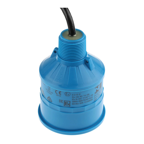
Ultrasonic transducers
Hide thumbs
Also See for XPS10:
- Quick start manual (117 pages) ,
- Operation manual (117 pages) ,
- Compact operating instructions (60 pages)
Table of Contents
Advertisement
Advertisement
Table of Contents

Subscribe to Our Youtube Channel
Related Manuals for Siemens XPS10


Summary of Contents for Siemens XPS10
- Page 1 Ultrasonic Transducers XPS10/15F Operating Instructions 08/2013...
- Page 2 The user is responsible for all changes and repairs made to the device by the user or the user’s agent. All new components are to be provided by Siemens Milltronics Process Instruments. Restrict repair to faulty components only.
-
Page 3: Table Of Contents
Table of Contents Table of Contents .................. i About Siemens’ Transducers.............. 1 Hazardous Area Applications ........... 1 Specifications ..................2 XPS 10 F Series Transducers..........2 XPS 15 F Series Transducers..........3 Outline and Dimensions ..............4 XPS 10 F Series Transducers..........4 XPS 15 F Series Transducers.......... - Page 4 Page ii XPS 10/15 F Series Transducer A5E32725813...
-
Page 5: About Siemens' Transducers
The Echomax XPS F series of transducers can be used in hazardous areas. For the XPS 10 F series transducer, a hazardous seal must be used to suit hazardous area classification. This seal is not supplied by Siemens. The XPS 15 F comes equipped with a stainless steel coupling suitable for use in hazardous locations. -
Page 6: Specifications
ANSI cable: 2-wire shielded / twisted, 0.5 mm (20 AWG) PVC jacket Supply Source Transducer shall only be supplied by a Siemens certified controller. Weight 0.8kg (1.8lb) Separation 365m (1200ft) from transducer Approvals FM Class 1 Div 1, Group A, B, C and D ... -
Page 7: Xps 15 F Series Transducers
ANSI cable: 2-wire shielded / twisted, 0.5 mm (20 AWG) PVC jacket Supply Source Transducer shall only be supplied by a Siemens certified controller. Weight 2.0 kg (4.4lb) Separation 365m (1200ft) from transducer Approvals FM Class 1 Div 1, Group A, B, C and D ... -
Page 8: Outline And Dimensions
7ML19981EG01) Note: For the XPS 10 F series transducer, a hazardous seal must be used to suit hazardous area classification. This seal is not supplied by Siemens. For more information, refer to page 20. Page 4 XPS 10/15 F Series Transducer... -
Page 9: Xps 15 F Series Transducers
(10.0”) to suit ANSI standards 158mm (6.2”) Refer to submergence shield instructions (Siemens’ manual number 7ML19981EG01) Note: The XPS 15 F comes equipped with a stainless steel coupling suitable for use in hazardous locations. A5E32725813 XPS 10/15 F Series Transducer... -
Page 10: Mounting
On liquid applications, the transducer must be mounted so that the axis of transmission is perpendicular to the liquid surface. On solids applications, a Siemens Easy Aimer should be used to facilitate aiming of the transducer. Do not over-tighten mounting. Hand tightening of the mounting hardware is sufficient. -
Page 11: Liquid Applications
Notes: In, the examples that follow, an XPS 10 F Series transducer is shown using a hazardous seal. This seal is not supplied by Siemens. An XPS 15 F transducer can also be used in these applications, but, because it comes equipped with a stainless steel coupling, no hazardous seal is required. - Page 12 Blind Flange (XPS 10 F shown) nipple welded to bind flange hazardous seal (XPS 10 F only) Flange, gasket, hazardous seal and hardware supplied by customer. Refer to page 13 Flanged (XPS 10 F shown) hazardous seal (XPS 10 F only) factory flanged transducer bolt...
-
Page 13: Interconnection
Interconnection Note: Installation should only be performed by qualified personnel and in accordance with local governing regulations. Recommendations When using an XPS 15 F transducer, configure the electronic transceiver for an XCT-12. These two transducers use the same settings. ... - Page 14 2-Wire Extension (XPS 10 F shown) Hazardous Location Non-Hazardous Location (Class I, Div. 1, Group (Safe) A,B,C,D or Class II, Div. 1, Group E,F,G) junction box drain / shield metal conduit extend cable using 18 AWG shielded / twisted pair Note: When connecting to SITRANS LUT400, SITRANS LUC500, MultiRanger 100/200, or HydroRanger 200, the...
-
Page 15: Applications
Applications Notes: The transducer is to be used only in the manner outlined in this instruction manual. Normally, the transducer requires no cleaning or maintenance. However, if performance changes are observed, immediately shut down the level measurement system and perform a thorough inspection, especially on the transducer. - Page 16 Note: Refer to transceiver manual for programming requirements. hazardous seal (XPS 10 F only) transducer submergence shield* (Refer to Siemens instruction manual 7ML19981EG01 for assembly details) air pocket * on applicable models Page 12 XPS 10/15 F Series Transducer...
- Page 17 Standpipes In many applications, access must be made via a standpipe. In such cases, Siemens can provide factory bonded flanged transducers or a split flange kit that will readily mate to the flanged standpipe. Another option is to hang the transducer from a blind flange.
- Page 18 When used in hazardous areas, the XPS 10 F series transducer (shown) must use a hazardous seal. This seal is not supplied by Siemens. The XPS 15 F Series transducer comes equipped with a stainless steel coupling suitable for use in hazardous locations.
- Page 19 Water / Wastewater Differential Level Pump Control Sewage Lift A5E32725813 XPS 10/15 F Series Transducer Page 15...
-
Page 20: Solids Applications
Solids Applications Typical Transducer angled to avoid seams in bin wall and aimed at discharge in order to read bin when empty. Avoid intersecting bin wall seams, structural members and wall irregularities. bin wall seams filling profile emptying profile Transducer too close to material inlet. Falling material will intersect sound beam and cause erroneous readings or loss of echo. - Page 21 On fluid like solids, aim transducer perpendicular to material surface. minimal angle of repose discharge On dual discharge bins, aim each transducer at the discharge point. transducer A5E32725813 XPS 10/15 F Series Transducer Page 17...
- Page 22 Transducer should be aimed away from wall projections. When used in hazardous areas, the XPS 10 F series transducer (shown) must use a hazardous seal. This seal is not supplied by Siemens. The XPS 15 F Series transducer comes equipped with a stainless steel coupling suitable for use in hazardous locations.
- Page 23 Transducer should be mounted perpendicular to slope of wood chips. When used in hazardous areas, the XPS 10 F series transducer (shown) must use a hazardous seal. This seal is not supplied by Siemens. The XPS 15 F Series transducer comes equipped with a stainless steel coupling suitable for use in hazardous locations.
-
Page 24: Installation Diagram For The Xps 10 F
Installation Diagram for the XPS 10 F Page 20 XPS 10/15 F Series Transducer A5E32725813... - Page 25 Notes...
- Page 26 Notes...
- Page 28 For more information www.siemens.com/level www.siemens.com/continuous-weighing Siemens AG Subject to change without prior notice Industry Sector A5E32725813 Rev. AA 1954 Technology Drive P.O. Box 4225 *A5E32725813* © Siemens AG 2013 Peterborough, ON Canada K9J 7B1 Printed in Canada email: techpubs.smpi@siemens.com www.siemens.com/processautomation...
Need help?
Do you have a question about the XPS10 and is the answer not in the manual?
Questions and answers