Table of Contents
Advertisement
Advertisement
Table of Contents

Subscribe to Our Youtube Channel
Related Manuals for Kodak 2400DSV-E


Summary of Contents for Kodak 2400DSV-E
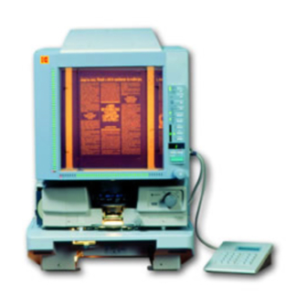
- Page 1 2400DSV-E Digital Scanner-Printer Operator’s Manual A-61316...
-
Page 2: Safety Warnings
• If this product becomes inordinately hot or emits smoke, or unusual odor or noise, immediately turn OFF the power switch, unplug the power cord from the power outlet, and then call your Kodak Service Representative. A fire or electrical shock could result if you continue to use the product. - Page 3 Caution symbols • Do not use flammable sprays, liquids, or gases near this product, as fire could result. • Do not let any object plug the ventilation holes of this product. Heat could accumulate inside the product, resulting in a fire or malfunction. •...
- Page 4 Routine Precautions • Do not store toner units, PC drum units, and other supplies and consumables in a place subject to direct sunlight and high temperature and humidity, as poor image quality and malfunction could result. • Do not attempt to replace the toner unit and PC drum unit in a place exposed to direct sunlight. If the PC drum is exposed to intense light, poor image quality could result.
-
Page 5: Table Of Contents
Grounding ..................1-3 Space requirements................1-3 Operating environment ..............1-4 System configuration ..............1-5 2400DSV-E Scanner/Printer components ........1-6 2400DSV-E Scanner/Printer optional accessories ......1-7 Turning the power on and off ............1-9 Auto Power Save/Projection Lamp functions........1-10 Control Panel Functions ..............2-1 Standard control panel functions ............2-1 Using the Sift function on the control panel ........2-6... - Page 6 Clearing misfeeds from the paper cassette ........6-4 Clearing misfeeds from inside the printer ........6-6 Solving printing problems..............6-8 Appendix A Specifications ..............A-1 Kodak 2400DSV-E Scanner/Printer..........A-1 High-Speed Video Laser Printer .............A-2 Appendix B User and System Settings..........B-1 Appendix C Key Operator Information ..........C-1 New equipment warranty ..............C-1...
-
Page 7: Introduction
Introduction This Operator’s Manual provides information and procedures for using the Kodak 2400DSV-E Digital Scanner-Printer. Following is a summary of what is included: Chapter 1, Introduction provides general information about the Kodak 2400DSV-E Scanner-Printer including a product description, installation information, environmental specifications, an overview of external components, and how to turn the scanner and printer on and off. -
Page 8: Product Descripton
The Kodak 2400DSV-E Digital Scanner-Printer scans images and outputs Product description to a printer or through the PC interface. All controls are mounted on the front panel for ease of operation. You can scan directly to the optional laser printer or to a PC at up to 800 dpi. -
Page 9: Power Source
Space requirements 2400DSV-E Scanner The illustration below provides the clearance dimensions between the wall and the rear of the unit as well as the right and left sides which provide ample space for the ventilation ports to dissipate heat. - Page 10 High-Speed Video Laser Printer For ease of operation, maintenance and replenishment of supplies, the minimum clearance shown below is required. Install the unit in an area that allows easy access. A-61316 September 2004...
-
Page 11: Operating Environment
The scanner is connected to a dedicated printer, allowing scanned images to be printed out directly. NOTE: Each 2400DSV-E Scanner is designed exclusively for use with its respective printer. Contact your Kodak Representative if you are in doubt on how to connect the laser printer. - Page 12 ACF-7 ― for automatic loading, viewing and ejection of aperture cards and works in medium- to high-volume applications. The ACF-7 is recommended for the Kodak 3000DSV-E Scanner-Printer but can be used with the 2400DSV-E Scanner-Printer providing the image area of the film is completely visible on the screen.
-
Page 13: 2400Dsv-E Scanner/Printer Optional Accessories
Auto Lighter Both ends of Exposure Display blink. If you want the Print Reserve/Memory Function disabled, contact your Kodak Service Representative. To turn the power off: • Press the Power switch of the scanner and printer to the O (Off) position. -
Page 14: Auto Power Save/Projection Lamp Functions
These functions may be disabled or enabled. When enabled, timing can be selected from either 30 or 60 minutes. The default for both of these functions is Disabled. Contact your Kodak Service Representative for more information. When the system is in the Auto Power Save mode, each outside segment of the Multi-Print Display LEDs light up sequentially. -
Page 15: Control Panel Functions
Control Panel Functions Following are descriptions of the Control Panel functions. Some functions are available by using the Shift key and some of the functions provide access to optional accessories. This chapter provides an overview of each function. Chapter 3, Using the Scanner, provides procedures on how to use each function. - Page 16 Auto Skew Correction key - turns auto skew on or off. When auto skew is on, the indicator is lit and any skew of the image will be corrected during printing. After printing, the skew is retained by default. Contact your Kodak Service Representative to change the default. A-61316 September 2004...
- Page 17 Centering/Fit key - when pressed, enables or disables the Centering and Fit functions. When Auto Masking, Trimming or Masking are set to Off, Auto Masking will automatically be enabled when Centering is selected. Centering: places a screen image that was searched using Auto Masking or an image that was trimmed in the center of the page.
- Page 18 Print Mode key - allows you to fine-tune the image quality of the print according to the original. When pressed, cycles through Text, Fine and Photo. • Text: for use with text images. • Fine: for use with lower grades of film. •...
- Page 19 13 Memory Input indicator - allows you to store one of the following functions into the memory of the scanner. • Negative or positive • Print mode • Output Format • Print image density • Exposure mode • Centering or Fit •...
-
Page 20: Using The Sift Function On The Control Panel
User Mode (Output Selection key) – pressing this key together with the Shift key puts the Scanner-Printer into the User mode. The User mode allows you to change the default values of various functions. Contact your Kodak representative for more information. A-61316 September 2004... - Page 21 Lamp Illuminance (Centering/Fit key) - adjusts the illumination of the screen. To adjust: • Hold down the Shift key while pressing the Centering/Fit key until the desired contrast is achieved. When this key is continuously pressed, the screen is gradually darkened until it is turned off. When the screen is turned off, you can press any key to illuminate the screen to the maximum level.
-
Page 22: Using The Scanner
Using the Scanner This chapter provides procedures on how to use the Kodak 2400DSV-E Scanner. Following is an outline of the basic printing procedure. Detailed procedures on these steps can be found later in this chapter. 1. Load the film. The procedure for loading film is determined by the type of Film Carrier (optional) that is being used. -
Page 23: Selecting A Projection Lens
Projection lenses are available in the following types. Select the type of Selecting a projection lens that corresponds to the film you are using. lens Type 1: 7.5X Type 1: 9 x 16 Type 2: 13 to 27X Type 3: 23 to 50X The list below shows the standard types of film and the recommended zoom ratios of lenses to be used with the scanner. -
Page 24: Installing A Projection Lens
To install a lens with a magnification different from the pre-installed lens: Installing a projection lens 1. Grasp the Prism Holder lever and pull it up. 2. Pull out the lens unit. 3. Slide the lens unit into the machine along the lens guide. 4. -
Page 25: Selecting The Connection Mode (Pr/Pc)
Images are scanned and output to the Video Laser Printer or through the Selecting the PC interface. You can use the PR/PC key to switch between Printer Connection mode mode and PC mode if you are connected to a (PR/PC) PC mode ―... -
Page 26: Zooming And Focusing Images
Zooming in on the displayed image: Zooming and focusing images 1. Rotate the Zooming Ring dial to bring the image on the screen into print size frame. Marked on the screen are the size frame markers corresponding to the paper size 8.5x 11-inch (A4). A4 (8.5 x 11") Width A4 (8.5 x 11") -
Page 27: Rotating Images
To rotate the image on the screen: Rotating images • Turn the Image Rotation knob until the image is displayed at the desired rotation. The greater the turning angle of the Image Rotation knob, the faster the turning speed. NOTE: If you hold down the Shift key and turn the Image Rotation knob, the image quickly rotates by 90 degrees. -
Page 28: Selecting The Image Density
The Exposure Adjustment keys (Darker and Lighter keys) on the Control Selecting the image Panel are used to adjust the density of the image to be printed during the density Auto or Manual Exposure mode. • Darker: makes the image density darker. •... -
Page 29: Using Manual Exposure
1. Press the Auto key to select the Manual Exposure mode. The Auto Using Manual exposure Exposure indicator will not be illuminated when Manual Exposure is selected. Darker Auto Lighter 2. Press the Darker or Lighter key to set the desired image density or exposure level. -
Page 30: Selecting The Output Format
The Output Selection key is used to select the paper source and print Selecting the output format. format Output Selection Tray Cassette1 • Tray ― prints the displayed image on paper fed from the Print tray. • Cassette1 ― prints the displayed image on paper fed from cassette 1. •... -
Page 31: Selecting The Print Format
The Print format can be selected by using the Output Selection key. Selecting the print format Output Selection Tray Cassette1 Display Paper Feeding Description Lengthwise Prints the on-screen lengthwise area. Crosswise Prints the on-screen crosswise area. Lengthwise Prints the on-screen crosswise area. Crosswise Prints the on-screen lengthwise area. -
Page 32: Iimage Processing Features
This section provides a description of the image processing features and Image processing procedures for how to adjust and use them. Image processing features features include: Screen image → Print Image Description The black borders that run along the edges Auto Masking (1 Frame) of the image are masked. -
Page 33: Using Auto Masking
Screen image → Print Image Description Magnifies the displayed image according to Image Zoom the size of the paper being used. The range of magnification is 1.55X for ledger; 1.27X for legal, 1.41X for A3/11 x 17” and 1.22X for B4 sized paper. NOTE: This function is only available when the High-Speed Video Laser Printer is connected. -
Page 34: Using Manual Masking (Option)
Selecting auto masking • Press the Auto Masking key to turn this function on. Auto Masking Manual Masking can be performed manually if you have purchased the Manual Using manual masking Frame Masking Kit. Manual Masking allows you to specify any area for (option) printing of the displayed image using the Trimming and Masking features. - Page 35 Defining the print area for trimming or masking The trimming and manual masking procedures are the same. Use the following procedures for either feature. Trimming ― automatically masks the non-image area when the image is printed/scanned. Masking ― prints/scans only the image outside the area that is defined on the screen.
-
Page 36: Using Centering And Fit
Once the image has been trimmed or masked, the Centering function Using Centering and moves the image to the center of the print. The Fit function, however, fits the image on the screen onto the entire surface of the print. Screen Image Print Image Centering Off... -
Page 37: Cycle Print Mode
Images are manually loaded onto the carrier glass in between cycles. The Cycle Print setting must be enabled. If you want to use Cycle Print mode, connect your Kodak Service Representative. NOTE: This function is only available when using the Printer mode. Setting the interval The chart below provides the time intervals that can be set between scanning operations. -
Page 38: Using Cycle Print Mode
The Cycle Print mode will operate until it is cancelled. After the first Using Cycle Print mode scanning operation has finished, the system automatically scans the next image following a preset period of time. 1. After entering the Cycle Print mode, press Start. Start 2. -
Page 39: Selecting The Resolution
The table below shows the resolution values that can be obtained in the Selecting the PR and PC mode. resolution Connection mode Resolution Display 400 dpi PR mode 600 dpi 200 dpi 300 dpi PC mode 400 dpi 600 dpi 800 dpi To set the resolution for scanning or printing: 1. -
Page 40: Setting And Recalling Job Programs
The current setting can be set up to 3 program registration locations (1J, Setting and recalling 2J and 3J) for both the Printer connection and the PC connection. Once Job Programs the Job Programs have been set you can recall them as needed. The Memory Input key allows you to store one of the following functions into memory: •... -
Page 41: Recalling Job Programs
To recall a registered Job Program: Recalling Job Programs 1. Press the Shift and Job Recall keys at the same time. NOTE: Each time the Job Recall key is pressed while holding down the Shift key, the display rotates through 1J, 2J, 3J. Job Recall Shift 2. -
Page 42: Adjusting Screen Illumination
Changing settings with changed as necessary. Most of these functions are set-up and changed the User mode by your Kodak representative, however some User modes can be changed by you. Setting these default values according to your needs saves time and allows you to work more efficiency. -
Page 43: Entering And Exiting The User Mode
1. Hold down the Shift key and Output Selection key at the same time. Entering and exiting The Multi-Print Display displays a “U”. the User mode 2. Press the Exposure Adjustment key (Darker or Lighter) to select the specific function: U2, U6 or U7. •... -
Page 44: Correcting Image Distortion
Correcting Image changed as necessary. Most of these functions are set-up and changed Distortion by your Kodak representative, however some User modes can be changed by you. 1. Press and hold the Shift key and the Output Selection key to enter User mode. -
Page 45: Year, Month And Date Set Mode
The print pattern for the Date Print function can be set with this function. Year, Month and Date Set mode 1. Press and hold the Shift key and the Output Selection key to enter User mode. 2. Select U6. 3. Press the Exposure Mode key to display d*. The table below shows the amount of time based on the setting value. -
Page 46: Set Imprint Mode
If the time of day becomes incorrect for the Date function, you can reset it Set Imprint mode by following the procedure below. 1. Press and hold the Shift key and the Output Selection key to enter User mode. 2. Select U7. 3. -
Page 47: Printer Functions
Printer Functions This chapter provides general information about the High-Speed Video Laser Printer including an overall description of external components, use and care of the printer and printer supplies. Following is a list of the standard components of the Laser Printer. Parts of the printer Upper Unit Lock Release Lever ... - Page 48 Upper Unit open to replace the imaging cartridge and to clear misfed sheets of paper. Image Transfer Roller transfers the image onto a sheet of paper. Avoid touching it with your bare hands. Fusing Unit permanently fixes the image onto the sheet of paper.
-
Page 49: Using The Printer
To ensure the best performance of the printer, follow the precautions Using the printer below: • NEVER open any cover, or turn OFF the printer during printing. • NEVER bring any magnetized object or flammable gas or liquid close to the printer. -
Page 50: Cleaning The Printer
Before cleaning, turn the power off and unplug the cord from the power Cleaning the printer outlet. • Clean the printer at regular intervals. The printer should be cleaned with a soft cloth. Never use abrasives or corrosive detergents. • Clean the exterior panels with a soft, dry cloth. A damp cloth and a mild home detergent can be used for heavier cleaning. -
Page 51: Loading Paper Into The Paper Feeding Tray
Loading paper into the To load paper into the paper feeding tray: paper feeding tray 1. Open the paper feeding tray. 2. Fan the paper stack thoroughly and align the edges. 3. Load the paper stack face up in the tray and adjust the paper guides to secure the paper stack. -
Page 52: Loading Paper Into The Paper Cassette
Loading paper into the To load paper into the paper cassette: paper cassette 1. Pull the cassette out of the printer and open the cover. 2. Press down the Paper Lifting Plate until it locks. Fan the paper stack thoroughly, align the edges, and place the paper in the cassette. 3. -
Page 53: Replacing The Toner
Replacing the toner To replace the toner cartridge: 1. Open the upper unit by pulling the Upper Unit Lock Release Lever forward. 2. Remove the old imaging cartridge from the printer. 3. Take a new imaging cartridge out of the box. Holding it with both hands, shake it well in the direction indicated by the arrows. - Page 54 5. Shake the imaging cartridge four or five times as shown to evenly distribute the toner inside. 6. Slide the pins located on both sides of the imaging cartridge into the grooves of the printer as shown and gently push the imaging cartridge securely into place.
-
Page 55: Maintenance
Maintenance This chapter provides maintenance procedures for: • Cleaning the scanner • Replacing the projection lamp The scanner should be cleaned daily for optimal operating conditions. Cleaning the scanner Screen • With a damp cloth, clean and remove any dust or debris from the surface of the screen. - Page 56 Carrier Glass (option) Before cleaning the carrier glass, remove the projection lens from the scanner. 1. With a damp cloth, clean and remove any dust or debris from the surface of the carrier glass. 2. To open the carrier glass, pull out the handle of the microfiche holder. Wipe the inner surfaces of the carrier glass with a damp cloth.
-
Page 57: Replacing The Projection Lamp
Use the following procedure to replace the projection lamp whenever a Replacing the reduction in brightness on the screen is detected or the lamp burns out. projection lamp If the projection lamp burns out during a print operation, the L2 code will appear and the print job will stop. - Page 58 4. Remove the projection lamp from the lamp socket. 5. Insert a new projection lamp so that the mark on its base is facing upwards. Make sure the new projection lamp is inserted securely so there is no gap between the projection lamp and the lamp socket. IMPORTANT: Do not touch the reflector mirror surface of the projection lamp.
- Page 59 7. Slide the projection unit back into the machine. NOTE: If the projection unit is not properly installed, power will not be supplied and the machine will not operate. 8. Turn the power switch on. A-61316 September 2004...
-
Page 60: Troubleshooting
Malfunction procedure — if the Misfeed/Call Tech Rep Code is displayed, a paper misfeed or malfunction has occurred in the system. Check the code shown on the Multi-Print Display and perform the misfeed clearing procedure. If the error persists, contact Kodak. Code... -
Page 61: Clearing Misfeeds From The Paper Feeding Tray
Call Tech. Rep. Procedure — if one of the following codes is displayed, a malfunction has occurred in the system. After turning the power off and unplugging the power cord, contact your Kodak Service Representative. Location Code Description Optical path switching failure. - Page 62 2. Remove the imaging cartridge. NOTE: Be sure to cover the imaging cartridge with a heavy cloth to protect it from light when it is removed from the printer. 3. Remove the sheet(s) of paper that caused the misfeed from the paper feeding tray.
-
Page 63: Clearing Misfeeds From The Paper Cassette
Following are procedures for clearing a misfeed from the paper cassette. Clearing misfeeds from the paper cassette 1. Open the upper unit by pulling the upper unit lock release lever forward. NOTE: Push the paper cassette into before opening the upper unit. 2. -
Page 64: Clearing Misfeeds From Inside The Printer
Following are procedures for clearing a misfeed from the inside of the Clearing misfeeds from printer. inside the printer 1. Open the upper unit by pulling the upper unit lock release lever forward. NOTE: Push the print tray in before opening the upper unit. 2. - Page 65 4. If the misfeed occurred after the sheet of paper entered the fusing unit, gently pull the misfed sheet toward you and out as shown. NOTES: • Since the toner has not yet been fixed onto the sheet of paper, be careful not to soil you hands or clothes when pulling out the misfed sheet.
-
Page 66: Solving Printing Problems
Partial void image dry paper. Toner in the imaging cartridge is Remove the imaging cartridge, shake Uneven image density not evenly distributed. it several times and replace. The printer has malfunctioned. Contact your Kodak Service Blank print Representative. A-61316 September 2004... -
Page 67: Appendix A Specifications
Appendix A Specifications Following are specifications for the Kodak 2400DSV-E Scanner/Printer. Desktop-type Microfilm Scanner Type 200, 300, 400, 600, 800 dpi (in PC mode) Resolution 400, 600 dpi (Printer mode: when the Printer is connected) PC mode: binary, grayscale (option) - Page 68 Following are specifications for the High-Speed Video Laser Printer. Type Microfilm Scanner/Printer System Printing method Laser Electrostatic Resolution 400, 600 dpi Developing Fine Micro-Toning (Fine-MT) System system 8 ½ x 11” (A4) crosswise, 11 x 17” (A3) lengthwise Print size 8 ½...
- Page 69 This system offers two types of settings: • User settings that are setup by the operator from the control panel • System settings that are setup and can be changed by the Kodak Service Representative. Following is a list of factory settings:...
- Page 70 Disabled (PR mode only) following a preset period of time (the period can be set by Disabled your Kodak Service Representative). Images are set by the user onto the Carrier Glass between cycles. Paper size of Paper Lengthwis Determines the desired paper size from the Paper...
-
Page 71: Kodak 2400Dsv-E Scanner/Printer
• Your company name, address, telephone number, department name, floor number, machine location, etc. • K# (Mainframe and/or Printer), model name, serial number, condition or system(s) indication(s) on the display, etc. For your reference purposes: Kodak 2400DSV-E Scanner/Printer Serial No. Model Name High-Speed Video Laser Printer Serial No. -
Page 72: New Equipment Warranty
This limitation of liability will not apply to claims for injury to persons or damage to property caused by the sole negligence or fault of Kodak or by persons under its direction or control. The High-Speed Video Laser Printer has a rated Print Life of 360,000 print actuations. - Page 73 EASTMAN KODAK COMPANY Document Imaging Rochester, New York 14650 Kodak is a trademark of Eastman Kodak Company. Printed on recycled paper. DOCUMENT A-61316 9/04 IMAGING CAT No. 199 6768 Eastman Kodak Company, 2004...
Need help?
Do you have a question about the 2400DSV-E and is the answer not in the manual?
Questions and answers