Table of Contents
Advertisement
Quick Links
Advertisement
Table of Contents

Related Manuals for AOR AR-ALPHA


Summary of Contents for AOR AR-ALPHA
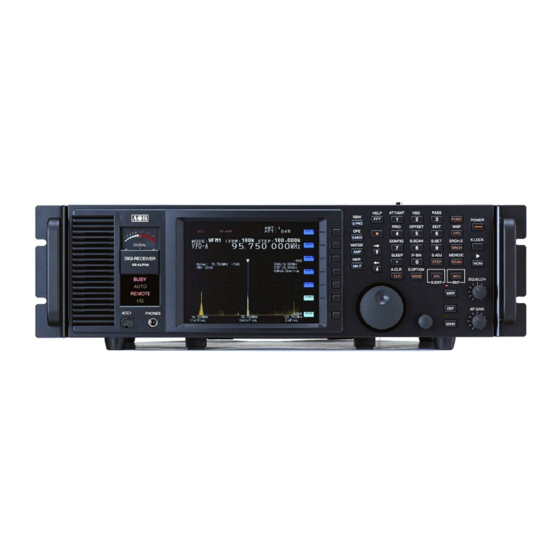
- Page 1 ® AR-ALPHA Digital Processing Communications Receiver Operating Manual AOR, LTD.
-
Page 3: Table Of Contents
1-5-1 Keypad ----------------------------------------------------------------------------------14 1-5-2 Summary of keys ----------------------------------------------------------------------14 Rear Panel ----------------------------------------------------------------------------------29 2. Getting Started ----------------------------------------------------------------------------------------------33 2-1 Preparing the AR-ALPHA for operation ----------------------------------------------------------33 2-1-1 Connecting the antenna ----------------------------------------------------------33 2-1-2 Connecting power ----------------------------------------------------------------------33 2-2 Switching on for the first time ----------------------------------------------------------------------34 2-3 Squelch Circuit... - Page 4 4. Memory channels ----------------------------------------------------------------------------------------------56 4-1 Memory Bank and Memory Channel ----------------------------------------------------------56 4-2 Storing VFO frequency and data into memory ----------------------------------------------57 4-3 Memory read “M.RD” --------------------------------------------------------------------------------- 58 4-4 Memory Mode ----------------------------------------------------------------------------------59 4-4-1 From Bank List screen to MemBank screen or Browser ----------------------60 4-4-2 From Bank List to MemCh List ----------------------------------------------61...
- Page 5 9. Computer control ---------------------------------------------------------------------------------------------102 9-1 How to send a control command ---------------------------------------------------------102 9-2 Power on ---------------------------------------------------------------------------------------------102 9-3 Detailed control command list of the AR-ALPHA ---------------------------------------------103 10. Specifications -------------------------------------------------------------------------------------------------------124 11. I/Q digital output in details for developers ---------------------------------------------------------126 12. Reset ---------------------------------------------------------------------------------------------------------133 13.
- Page 6 15. Limited Warranty (USA only) ---------------------------------------------------------------------------------139 16. Control software ----------------------------------------------------------------------------------------------141 16.1 Minimum system requirements -----------------------------------------------------------------143 16.2 USB driver installation ------------------------------------------------------------------------------144 16.3 I/Q driver installation --------------------------------------------------------------------------------147 16.4 Software installation ---------------------------------------------------------------------------------149 16.5 Software registration (single PC & multiple PC) -------------------------------------------150 16.6 Software functions -----------------------------------------------------------------------------------152...
-
Page 7: Introduction
© This manual is protected by copyright AOR, LTD. 2010. No information contained in this manual may be copied or transferred by any means without the prior written consent of AOR, LTD. AOR and the AOR logo are trademarks of AOR, LTD. All other trademarks and names are acknowledged. - Page 8 Main features: Wide frequency coverage: 10 kHz to 3.5 GHz, with no interruptions (USA consumer version has cellular telephone frequencies blocked) Zero-IF frequency (for the 3 DDS (Direct Digital Synthesizer) local oscillator TV reception in NTSC, PAL, and SECAM formats I/Q output with 1 MHz bandwidth Multi-mode unit capable of receiving AM (Synchronous), ISB, RZ-SSB, USB, LSB, CW, WFM including FM stereo (when using optional headphones), NFM and APCO P25 digital...
-
Page 9: Caring For Your Radio
The AR-ALPHA is designed for operation from a high quality regulated DC supply of 12 to 14 V, which should be capable of supplying at least 2.2A. Never connect the AR-ALPHA directly to an AC outlet. -
Page 10: Please Note These Operating Procedures
3. Currently displayed VFO data is saved at power down (to increase speed of the operation and to reduce write cycles). For this reason, if the AR-ALPHA is powered down using the MAIN POWER (rear panel) switch or external power is removed, the last displayed frequency will be lost and the frequency used prior to this will be displayed the next time the receiver is powered up. - Page 11 Note: It is very important that the squelch is advanced to cancel background noise for the search & scan functions to operate properly. This is because the AR-ALPHA believes that it has found an active frequency when the squelch opens and the “BUSY” lamp lights up.
- Page 12 More details about the remarkable features of the AR-ALPHA Zero – IF (Zero Intermediate Frequency) Block diagram 1 shows a conventional triple conversion super heterodyne analog receiver and the 3 IF frequency is 455 kHz. Due to its frequency configuration, some “image” signals may be received.
- Page 13 The AR-ALPHA utilizes FFT (Fast Fourier Transform) technology for the spectrum display feature. FFT in the AR-ALPHA refreshes the spectrum display more than 10 times per second during a 10 MHz sweep (at 500 Hz RBW). The AR-ALPHA can display a wide range sweep up to 1 GHz.
- Page 14 AM (Amplitude Modulation) Envelope Detection (Normal AM decoder) Synchronous Detection 1. DSB (Double Side Band) synchronous 2. SSB (Single Side Band) USB/LSB (Upper Side Band/Lower Side Band) selectable synchronous 3. Side Band Diversity AGC (Automatic Gain Control) mode/Manual RF gain mode SSB (Single Side Band) USB/LSB selectable AGC mode/Manual RF gain mode...
-
Page 15: Controls And Functions
Analog output for DRM (Digital Radio Mondiale) 6 kHz IF (I/Q) analog output for DRM PC receiver 1-5 Controls & functions Controls are located on the front with most connectors on the rear of the AR-ALPHA. A brief identification is given here: Front Panel ①... -
Page 16: Keypad
Most keys have secondary functions, which are printed on the panel. However, due to the restrictions of available space, not all functions can be shown on the keypad. The secondary functions of the AR-ALPHA are indicated with white characters above each key. To access the secondary function, press the key, then press the respective key. - Page 17 WSP (Wide Span) mode. The WSP icon appears on the left of the frequency display. The AR-ALPHA can display up to 1 GHz of frequency bandwidth. To exit the WSP mode, press the VFO key.
- Page 18 To exit from the Scan mode, press the VFO key. MHz / ENT Press this key to have the AR-ALPHA accept data entry. When entering a frequency in MHz, use numeric keys followed by this key. KHz / S.ENT When entering a frequency in kHz, use numeric keys followed by this key.
- Page 19 To switch the Mode selection to “Advanced”, press the MODE key while the MODE select screen is displayed. Advanced Select Mode Press the key, then press the MODE key to go into the Additional digital mode. Press either the UP Arrow key or DOWN Arrow key to select the mode, and rotate the Sub Dial knob to change the parameter.
- Page 20 UP / RIGHT In the VFO mode: Pressing this key will increase the receive frequency by the currently selected frequency step. Press the key, then press this key to increase the receive frequency by 10 times the selected frequency step. In memory mode: Press this key to select a higher memory channel.
- Page 21 To cancel this operation, press the CLR key. AMP / WATER Press this key to set the input sensitivity level of the AR-ALPHA. There are six (6) different input sensitivity levels between 0 dBm and -50 dBm in 10 dB steps.
- Page 22 Pressing this key will illuminate a red lamp above the MKR switch. When the AR-ALPHA is in the VFO mode or Memory mode and the LCD is displaying frequency spectrum, the frequency marker cursor on the LCD screen can be moved by rotating the sub dial knob (small knob to the left of this key).
- Page 23 Pressing this key illuminates an orange lamp above the MAIN switch. When the AR-ALPHA is in the VFO mode, the function of the sub dial is the same as the main dial. While the MAIN lamp is illuminated, press this switch again until the orange lamp flashes; this enables the sub dial to change the receive frequency 10 times faster than the main dial.
-
Page 24: Soft Keys
Dial Knobs SUB DIAL (Small knob) The sub dial knob is used to change the parameters of various settings or to change the memory bank. MAIN DIAL (Large Knob) In the VFO mode, rotating this knob will change the receive frequency. In the Memory Mode, rotating this knob will change the memory channel. - Page 25 Lit when the AR-ALPHA is in automatic reception mode (AM, WFM, etc ). REMOTE Lit when the AR-ALPHA is controlled by a PC through the REMOTE 1 or REMOTE 2 connectors. While the REMOTE indicator is lit, all functions (except AF GAIN and SQUELCH CONTROL) are disabled Lit while I/Q signal is being sent through the USB port.
- Page 26 HEADPHONES Use a 1/4 inch stereo type plug. When a headphone is connected, the internal speaker is disabled. Ground Audio output (Right) Audio output (Left) Secondary functions of numeric keys Press the key, then press the 1 key. Selecting the attenuation level A soft key menu will appear at the right side of the LCD.
- Page 27 Selecting antenna input port Press the key, then press and hold the 1 key for 2 seconds A soft key menu will appear at the right side of the LCD. On this screen menu, choose one of the following four (4) selections. An optional AS5001 (or former AS5000) antenna switch is required to use more than 2 antenna inputs.
- Page 28 When the AR-ALPHA receives a signal and stops searching In Search Receive Mode, performing the above steps will register the frequency as a “pass” frequency and resume searching. The AR-ALPHA will not stop at a pass frequency during future search cycles.
- Page 29 Rotate the sub dial to select or set the desired priority channel. Press the down arrow key to move the cursor downward. Rotate the sub dial to set the priority time interval between 1 ~ 99 seconds. Press the MHz key to confirm entry. Press the key, then press the 5 key.
- Page 30 Configuration Setting The receiver’s configuration can be set on this screen. To exit this function, press the MHz key. Press the key, then press the 8 key. Select Memory Scan Setting Performing the above steps will activate the select scan mode. The select scan function scans each memory channel regardless of memory bank selection.
-
Page 31: Rear Panel
Sleep Timer Setting Performing the above steps will activate the sleep timer function. The time counter and the clock icon appear at the top right of the LCD. The sleep timer can be set for up to 99 minutes in 1 minute increments. To set the timer, rotate the sub dial. - Page 32 1. ANT 1 Connector N type connector. Antenna impedance is 50Ω nominal. An optional AS5001 antenna relay switch can be connected to this connector. 2. ANT 2 Connector SO-239 type connector. Antenna impedance is 50Ω nominal. 3. 10 MHz Input Connector External 10 MHz reference signal input connector (BNC) 4.
- Page 33 Line output for stereo audio. An external amplifier can be connected to these RCA type jacks. 9. I/Q OUTPUT Connector USB 2.0 compatible I/Q data output of 300 kHz or 1 MHz selectable bandwidth. You need to install the AOR IQ driver provided on the CD, or download it at www.aorja.com.
- Page 34 The REMOTE RS-232C connector is designed for connection directly to the RS-232C serial port of a PC. No interface is required, a standard RS-232C straight cable is all that is necessary. Connections for a PC are as follows: AR-ALPHA DB-9 RS-232C cable Pin # 2...
-
Page 35: Getting Started
2-1 Preparing the AR-ALPHA for operation 2-1-1 Connect the antenna For reception, connect the antenna to either Antenna 1 or Antenna 2 on the rear panel of the AR-ALPHA. Usually, for signal reception below approximately 1 GHz, connect the antenna to the Antenna 2 connector (SO-239 type connector). -
Page 36: Switching On For The First Time
The AR-ALPHA will take approximately 4 ~ 5 seconds before information appears on the LCD. This is normal, as the microprocessor of the AR-ALPHA must complete an initializing process at the beginning... -
Page 37: Squelch Circuit
To return to LEVEL SQUELCH, repeat above steps. 2-4 VFO selection The AR-ALPHA has five (5) VFOs being identified as “VFO-A” through “VFO-E” at the top left of the LCD. The term VFO stands for ‘Variable Frequency Oscillator’ and in modern receivers refers to stored tuneable data that contains frequency, step, step-adjust, attenuator etc. -
Page 39: Changing Frequency Using The Main Tuning Dial
Example of frequency entry for 162.55 MHz Press the [1] key, [6] key, [2] key, [.] key, [5] key, and [5] key. Press the [MHz] key. Example of frequency entry for 954 kHz (0.954 MHz) Press the [9] key, [5] key, and [4] key. Press the [kHz] key. -
Page 40: Changing Receive Mode
For your convenience, receive mode and tuning step size have been pre-programmed into the AR-ALPHA auto-mode band plan at the factory to simplify operation of the receiver. If needed, the defaults may be manually overwritten at any time so that you may select an alternative receive mode and tuning step on any frequency. -
Page 41: Auto Mode Selection
Remember that auto-STEP and auto-MODE are linked, reselect the AUTO-MODE if either have been adjusted and you require the auto band plan selection. 2-5-2 Receive mode selection The AR-ALPHA has two (2) different mode settings, Simple Select Mode Setting and Advanced Select Mode setting. - Page 42 Simple Select Mode Setting Advanced Select Mode Setting In the Simple Select Mode Setting, a proper IF bandwidth is automatically selected with respect to the receive mode. In the Advanced Select Mode Setting, the receive mode and the IF bandwidth can be selected independently.
- Page 43 In the Advanced Select Mode setting, the following modes are available: FM, FMST, AM, SAM, SAL, SAH, USB, LSB, CW, ISB, SBD, RZ-S, AIQ, and AUTO. To make a selection, rotate the sub dial. To accept the selection, press the MHz key. Description Mode Remarks...
-
Page 44: Additional Decoding Modes
2-5-3 Additional decoding modes Press the key, then press the key. The D.Option setting sub menu screen will display on the screen. Use the key or key to select the desired decoder function. To change the setting, rotate the sub dial, then press the key. -
Page 45: Changing Tuning Step Size
U.S.A. is 10 kHz while in Europe and Japan, it is 9 kHz. For the above reasons, it is necessary to change the tuning step size according to local band plans. The AR-ALPHA has been pre-programmed at the factory with most of the band plan data (selectable... -
Page 46: If Bandwidth
Japan, Europe and the USA) so that the AR-ALPHA will automatically select the appropriate tuning step size and mode for the frequency chosen. This greatly simplifies operation of the AR-ALPHA. The factory pre-programming of step size can be manually overwritten so you may choose alternative settings at will, or when band plans are updated. -
Page 47: Manually Selecting If Bandwidth
Activating the attenuator reduces signal to the RF input stages of the AR-ALPHA to prevent overloading in cases where the receiver is used in close proximity to strong transmissions. The AR-ALPHA has five settings for ATT (attenuator), AMP ON 0 dB, AMP OFF 0 dB, 10 dB, 20 dB and AUTO. -
Page 48: Offset
OFFSET This function enables the receive frequency to be quickly SHIFTED by a predetermined value; this makes it easy to track duplex-transmissions or check repeater inputs/outputs. Frequency offset may also be programmed manually. The locations for frequency offset storage are numbered 00 to 47 with 00 acting as OFF, and the first 20 offsets are user programmable. -
Page 49: Entering New Frequency Offset Data
The Offset frequency set up screen will appear. Rotate the sub dial to select the desired pre-programmed offset frequency. To accept the offset setting, press the key. Below is a list of the pre-programmed offset frequencies. Channel number Offset frequency 100 kHz 4.0 MHz 4.6 MHz... -
Page 50: Activating Frequency Offset
2. The Offset frequency set up screen will appear on the LCD. 3. Rotate the sub dial to select the desired offset memory channel. 4. Using the numeric keypad, enter the desired offset frequency in MHz format. (The shift direction can be changed by pressing the kHz key.) (Example) For shift frequency 5 MHz, enter 5.00. -
Page 51: Deactivating Frequency Offset
5. The DUP icon will disappear from the screen to confirm operation. Spectrum Display Along with a high performance professional grade receiver, the AR-ALPHA has a built-in spectrum display function that will show frequency activity over a specified bandwidth on the LCD. -
Page 52: Operation Mode Display
3-1-1 Operation mode display FUNC Function mode Auto Notch NOTCH Voice Squelch Noise Reduction PRIO Priority Noise Blanker PASS Pass Memory Voice De-scramble Select Memory IF-SFT IF shift Automatic Frequency CTCSS Tone Squelch Control Digital Code Squelch DTMF DTMF Decode ANT: Antenna Input Duplex Mode... -
Page 53: Spectrum Display (Example)
Memory Scan mode (example) MODE Receive mode M00-00 Memory bank and memory channel IF-BW IF bandwidth Frequency Receiving frequency Memory channel tag NHK FM WSP (Wide Span) mode (example) (Note: No audio is available in WSP mode.) STEP Frequency step WSP mode Frequency Center frequency 3-1-3 Spectrum Display (example) - Page 54 Note: The value of the Marker and the RBW will change according to the MKR operation. The value of MAX.AVR or MED will be displayed next to RBW. Marker MAX (example) Peak AVR: 5 (example) C-Peak MED: 4 (example) Other display samples: Waterfall Display WSP Display Search Tag Edito r...
-
Page 55: Display Span Setting
When a soft key is displayed in a dark blue color, it is not selectable. Display span setting In the normal operation mode, the maximum display span is 10 MHz (+/- 5 MHz from the center frequency.) The chart at the left indicates the display span as 10 MHz and the display step is 20 kHz (per pixel). -
Page 56: Setting The Display Span
The display step can be manually set between 500 Hz and 20 kHz in 10Hz increments. In this mode, the display span is determined automatically. In some cases, it is more convenient to set the display span by entering the start frequency and the end frequency instead of setting the center frequency. - Page 57 Display span is set to 5 MHz. Setting the display span using the display frequency step (per pixel) (Example) Set the display frequency step to 1 kHz per pixel. Press the key, then press the soft key. Press the key, then press the key.
-
Page 58: Memory Channels
Text comment of up to 12 characters 4-1 Memory Bank and Memory Channel The AR-ALPHA features 2,000 memory channels and a priority channel. There are 40 memory banks (groups) and each bank has 50 memory channels. The alphanumeric comment may be used for easy identification of a specific memory channel at a future... -
Page 59: Storing Vfo Frequencies And Data Into Memory
having 50 channels. The memory banks are identified by the first BANK number 0, 1, 2, 3, 4, 5, 6, 7, 8 and 9 and the individual channels are numbered from 00 to 39. Examples are “00” for the first channel location in memory bank “0” and “39” for the last memory channel in memory bank “0”. -
Page 60: Memory Read "M.rd
Press and hold the key for 2 seconds. The VFO browser screen will appear on the LCD. Press the UP key to move the cursor to highlight the MemCh (Memory channel) in reverse color, then enter the desired memory bank and memory channel using the numeric keypad followed by the key. -
Page 61: Memory Mode
(Example) Read the memory bank 00, memory channel 02. Enter from the numeric key pad. (Note) If a vacant memory content is recalled, then the memory bank 00, memory channel 00 will be recalled. To return to VFO mode screen, press the key. -
Page 62: From Bank List Screen To Membank Screen Or Browser
The “VFO-A” icon changes to “M00-03” indicating the AR-ALPHA is in the Memory Mode. While in the Memory Mode, press the soft key to display the Bank List. Memory mode Press the key to browse through the bank list. Return to memory screen... -
Page 63: From Bank List To Memch List
Bank number Available free memory number Memory name tag Assigned memory channel number Write protect While above screen is displayed, press the key of the soft key to go into the Title Editor screen. Return to previous screen. Confirm title entry. Delete character. -
Page 64: From Memch List To Memch **.** Browser
Bank number Bank title Assigned channel number Channel number Bank number Cursor Unregistered channels Frequency Mode IFBW Pass Select Title Bank number: Current bank number Bank title: Named title for the bank Frequency: Stored receive frequency Mode: Stored receive mode IFBW: Stored IF bandwidth Pass Setting:... - Page 65 Title Channel Tag Freq. Receive frequency Mode Receive mode Antenna select CTCSS CTCSS setting IFBW IF bandwidth Attenuator DCS setting AGC setting DTMF DTMF setting StepAdj. Step adjust AFC setting IF-Inv. IF inversion Offset Offset Voice squelch setting NOTCH Notch filter IF-SFT IF shift Noise reduction...
- Page 66 ● Soft key operation and functions...
-
Page 67: Scan - Scanning Memory Channels
5. SCAN – scanning memory channels The AR-ALPHA has a SCAN mode whereby the contents stored in the MEMORY CHANNELS ARE AUTOMATICALLY RECALLED AND MONITORED very quickly, that is, “scanned” for activity. *** It is important that you do not confuse SCAN and SEARCH modes. *** SEARCH mode (covered later in this manual) automatically TUNES THE RECEIVER THROUGH ALL FREQUENCIES between two specified frequency limits, looking for active frequencies. -
Page 68: Scan Operation
Scan mode (searching) Scan mode (receiving) 5-3 Scan operation ① ① ① ① ① ① ① ①... -
Page 69: Changing Scan Direction
Item Operation ① MODE:NFM Receive mode ① IFBW:15k Receiver IF bandwidth ① M01-22 Bank 01, Channel 22 ① 399.462500 MHz Memory channel frequency ① MemCh01-22 Memory channel text VOICE Decoding mode: VOICE ① DTMF: AAAA DTMF decoded data ① M01-00Mem Ch01-00 398.030M Scan List ①... -
Page 70: Bank Link
5-5 Bank Link The AR-ALPHA has a built-in Bank Link function to allow scanning a single bank or a user-selected group of memory banks. 5-5-1 Setting Bank Link 1. Press the key, then press and hold the key for 2 seconds. -
Page 71: Start Select Scan
(Example) Adding select scan channels can also be performed in the memory channel browser screen. Memory channel browser 5-6-2 Start select scan Press the key, then press the key. -
Page 72: Channel Pass
Add the channel to the select memory. Transfer the cursor data to the newest list. Clear the displayed list. 5-7 Channel Pass When scanning, you may encounter active memory channels which you do not wish to currently monitor. It is possible to manually force the scan process to continue. 5-7-1 Setting channel pass 1. -
Page 73: Search
6. Search 6-1 Search Setting 6-1-1 Setting 1. Press and hold the key for 2 seconds. 2. The following screen will appear. 3. Press the key. 4. The following screen will appear. -
Page 74: Search Bank Browser Setting
6-1-2 Search Bank Browser setting Title Name Tag LoFreq. Lower limit freq. HiFreq. Upper limit freq. Antenna CTCSS CTCSS setting Mode Receive mode Attenuator DCS setting Step Frequency step AGC setting DTMF DTMF setting IFBW IF bandwidth AFC setting IF-Inv. IF inversion StepAdj. - Page 75 To change the Search Bank, enter a 2-digit number (00~39) from the numeric keypad. Go to PASS Freq. List. The frequency selected by the cursor will be sent to the VFO (using VFO-D). Move to the newest receive frequency. Delete all search list. ●...
-
Page 76: Search Group
Return to the Search List screen. Delete the frequency at the cursor in the PASS Freq. List. Delete all PASS frequencies from the frequency list. 6-2 Search Group The search function will tune continuously between two (2) selected frequencies in increments of the currently designated frequency step. - Page 77 Press the soft key to start group search. ● Soft key operation and functions key, then press the key. Press the Press and hold the Press the key.
-
Page 78: Fft Search
Unlike the ordinary search function that searches between a low frequency and a high frequency, the AR-ALPHA FFT search examines a 10 MHz block of band data. When more than 10 MHz of bandwidth needs to be searched, the AR-ALPHA will automatically continue the FFT search process in 10 MHz increments. -
Page 79: Fft Search Screen
7-1-1 FFT Search Screen Pause FFT search. Resume FFT search. Transfer the cursor frequency to VFO-D. Move the cursor to the latest position. Delete the frequency list searched by FFT. Return to the FFT search screen. - Page 80 ● Soft key function operation and functions Press the...
-
Page 81: Miscellaneous Settings
8. MISCELLANEOUS SETTINGS 8-1 Soft key registration The functions of the soft keys vary with respect to each operation screen. By assigning variable functions to each soft key, it is much easier to operate the AR-ALPHA. Soft Key function Soft key... -
Page 82: Soft Key Registration
As described above, using the assigned soft key will greatly simplify complex key operations. 8-2 Voice Recording The AR-ALPHA has a built in DVR (Digital Voice Recorder). Total recording time is up to 25 minutes (except in the WFM1/WFM2/FMST modes). There are five (5) recording memory channels. -
Page 83: Recording
In the CW mode, signals are recorded as mono. Quality of playback sound may be degraded as compared with the original signals even if recorded in the WFM mode or WAM mode. The receive mode should not be changed during the recording process. Never turn the main power switch off during recording, or loss of the recorded signal will result. -
Page 84: Changing Record Channel
4. The CUE icon will change to a green triangle icon indicating playback has taken place. 5. To stop playback, press the key. 8-2-4 Changing recorded channel Recording always takes place on channel 0. To save a recording to memory, the memory contents need to be moved to another vacant channel. -
Page 85: Moving Memory Bank
(MOVE / COPY) Move / copy MEM BANK MOVE Move memory bank Move contents of memory bank. MEM BANK COPY Copy memory bank Copy contents of memory bank. SRCH BANK MOVE Move search bank Move contents of search bank. SRCH BANK COPY Copy search bank Copy contents of search bank. -
Page 86: Copying Memory Bank
5. Rotate the sub dial to select the memory bank. (Above example shows bank 01). 6. Press the key to move the cursor. 7. Rotate the sub dial to select the desired memory bank. 8. Press the key to confirm entry. 9. -
Page 87: Moving Search Bank
8. Press the key to confirm entry. 9. At this point, the data of bank 01 is copied to bank 02. 10. The screen will return to the previous display screen. 8-3-3 Moving search bank 1. Press the key, then press the key. -
Page 88: Moving Memory Channel
4. The highlighted (in reverse color) number on the left side is the original search bank. 5. Rotate the sub dial to select the search bank. (Above example shows bank 01). 6. Press the key to move the cursor. 7. Rotate the sub dial to select the memory bank to be copied. 8. -
Page 89: Copying Memory Channel
8. Press the key to confirm entry. 9. At this point, the data of bank 00, channel 04 is deleted and moved to bank 01, channel 00. 10. The screen will return to the previous display screen. 8-3-6 Copying memory channel 1. -
Page 90: Copying Scan Group Data
4. The highlighted (in reverse color) number on the left side is the original scan bank group (00). 5. Rotate the sub dial to select the scan bank group. (Above example shows bank 01). 6. Press the key to move the cursor. 7. -
Page 91: Moving Search Group Data
7. Rotate the sub dial to select the desired scan bank. 8. Press the key to confirm entry. 9. At this point, the data of bank 02 is copied to bank 03. 10. The screen will return to the previous display screen. 8-3-9 Moving search group data 1. -
Page 92: Moving Recorded Voice Data
2. The data editor screen will appear. 3. Using the key or key, move the cursor to SRCH GR. COPY 4. The highlighted (in reverse color) number on the left side is the original memory bank and channel. 5. Rotate the sub dial to select the search bank. (Above example shows bank 02). 6. -
Page 93: Deleting Memory Bank
6. Press the key to move the cursor. 7. The screen will return to the previous display screen. 8-3-12 Deleting memory bank 1. Press the key, then press the key. 2. The data editor screen will appear. 3. Using the key or key, move the cursor to MEM BANK DEL. -
Page 94: Deleting Memory Channel
8-3-14 Deleting memory channel 1. Press the key, then press the key. 2. The data editor screen will appear. 3. Using the key or key, move the cursor to MEM CH DEL. 4. Rotate the sub dial to select the memory channel to be deleted. 5. -
Page 95: Deleting All Search Banks
3. Using the key or key, move the cursor to MEM BANK ALL. 4. Press the key to delete all memory banks. 8-3-18 Deleting all search banks 1. Press the key, then press the key. 2. The data editor screen will appear. 3. -
Page 96: Configuration Settings
8-4 Configuration settings The configuration menu is used to set fundamental operating parameters and other variables which do not appear in any menu heading. 1. Press the key, then press the key. 2. The configuration screen will appear. The description of each menu is as follows: BackLight Backlight On/Off of the display BEEP... -
Page 97: Configure Backlight
8-4-1 Configure backlit illumination The AR-ALPHA is equipped with a high density backlight lamp to illuminate the LCD when operating. To configure backlight illumination, perform the following steps: 1. Press the key, then press the key. 2. The configuration screen will appear. -
Page 98: Configure Reference Signal Input
8-4-4 Configure reference signal input This function enables you to select an external reference signal for the AR-ALPHA. The AR-ALPHA has a stable built-in reference oscillator, however, an external high stability 10 MHz reference (such as off-air, atomic coupled) can be accepted by the BNC connector, marked “10 MHz”, on the rear panel of the AR-ALPHA. -
Page 99: Video Display & Format
If that is the case, a signal can be descrambled by changing the shift direction. To do this, perform the following steps: 1. Set the AR-ALPHA in the VFO browser mode by pressing the “disp” soft key followed by the “VFO Browse” soft key. -
Page 100: Configure Voice Squelch Level
I/Q OUTPUT CONNECTOR To access the configuration menu, perform the following steps: 1. Press the key, then press the key. 2. The configuration screen will appear. 3. Press the key to move the cursor to I /Q BW. key or 4. -
Page 101: Configure Voice Level And Delay Time
(Note) VSQ-LV (squelch level) and VSQ –DL (delay time) may be set independently. 8-4-8 Configure PC interface The AR-ALPHA has one USB interface (REMOTE 1) and one RS-232C (REMOTE 2) serial interface. (Note: REMOTE 1 and REMOTE 2 cannot be used at the same time.) -
Page 102: Configure Sleep Timer
(Note) SERIAL, SPEED, FLOW may be set independently. 8-4-9 Configure Sleep Timer The AR-ALPHA has a sleep timer function where the receiver may be programmed to switch off after a preset time (1 to 98 minutes). To access the configuration menu, perform the following steps: (Example: Setting timer for 30 minutes) 1. -
Page 103: Configure Priority Function
5. When the power switch is turned off manually, or by the sleep timer, the timer will be reset. 8-4-10 Configure Priority function The priority function enables you to carry on scanning or monitoring while the AR-ALPHA periodically checks a selected frequency for activity. -
Page 104: Computer Control
Send a [CR] then re-send the command. Should a problem persist, check your connections or try reducing the baud rate. 9-2 Powering on the AR-ALPHA Connect a remote cable between the AR-ALPHA and a PC, type any key to power up the AR-ALPHA. -
Page 105: Detailed Control Command List Of The Ar-Alpha
9-3 Detailed control command listings for the AR-ALPHA ^A AC AF AG Remote power on Remote ON Hex value 0x01 ^Ann Accept a value nn in the range of 00-99 for remote connection ACn (n: 0 ~ 3) n = 0 (AGC Fast) - Page 106 Audio output select AQn (n: 0, 1) n = 0 Output : audio output n = 1 Output : I/Q output To read: AQ <CR> Response: Auto store (Cannot be used alone) ASn (n: 0, 1) n = 0 Auto store off n = 1 Auto store on Cannot be used alone.
- Page 107 Backlit display BLn (n = 0, 1) n = 0 Backlit off n = 1 Backlit on To read: BL <CR> Response: BP CF CL CN Beep BPn (n = 0, 1) n = 0 Beep off n = 1 Beep on To read: BP <CR>...
- Page 108 CW pitch frequency CPnn (nn: 30 ~ 50) in 5 increments (50 Hz step) (Example) nn = 30 300 Hz nn = 90 900 Hz To read: CP <CR> Response: CPnn Delay time (cannot be used alone) DLnn (nn: 01 ~ 99) Cannot be used alone.
- Page 109 DTMF (Function available in the VFO mode or memory mode) (n: 0, 1) n = 0 DTMF off n = 1 DTMF on To read: DT <CR> Response: EC EF EN EX Reference frequency input ECn (n: 0, 1) n = 0 Internal n = 1 External...
- Page 110 FFT search FFnn (n: 00 ~ 39) search bank FSnn (n: 00 ~ 12) search frequency step (see below chart) FTnnn (n: -0 ~ -110) threshold level To read: FF<CR> Response: FFnn FSnn FTnnn Parameter 00 01 Step (kHz) 10.0 12.5 20.0 25.0...
- Page 111 GN GR IF Input sensitivity of spectrum display GNn (n: 0 ~ 5) n = 0 0 dB n = 1 -10 dB n = 2 -20 dB n = 3 -30 dB n = 4 -40 dB n = 5 -50 dB To read: GN<CR>...
- Page 112 IF shift width ISnnn (nnn: -120 ~ +120) 50 Hz step, 5 increments nnn = -120 ~ -005 (minus shift) nnn = 000 (IF shift off) nnn = +005 ~ +120 (plus shift) Not available in all FM modes and RZ-SSB mode. To read: IS<CR>...
- Page 113 User defined keys (n: 0 – 9) n = 0 ~ 4 User defined key 1 ~ 5 n = 5 ~ 9 User defined key 6 ~ 10 S-meter level LM -------- Read only (in dB) Squelch setting LQnnn (n: 000 ~ 255) n = 000 Open...
- Page 114 MD MF Receive mode MDnn (nn: 00 ~ 39) See below chart To read: MD<CR> Response: MDnn Simple modes Advanced modes Parameter Mode Parameter Mode IFBW WFM1 100 kKHz FMST WFM2 200 kHz FMST 200 kHz 15 kHz 6 kHz 15 kHz 6 kHz 3 kHz...
- Page 115 Set pass channel (n: 0, 1) n = 0 Pass setting off n = 1 Pass setting on MPmm (mm: 00 ~ 39) Cancel pass function on the pass bank To read: MP<CR> Response: MPn or MPmm Call memory bank channel Write only MRmmnn mm: bank number...
- Page 116 Noise blanker (n: 0 ~ 3) n = 0 n = 1 n = 2 n = 3 High To read: NB<CR> Response: Noise reduction (n: 0 ~ 3) n = 0 n = 1 n = 2 n = 3 High To read: NR<CR>...
- Page 117 User defined offset frequency (Cannot be used alone) OLnnn.nnnnn (in MHz format) Cannot be used alone Use as the parameter of the OF command Display mode (n: 0, 1) n = 0 Spectrum analyzer mode n = 1 Channel scope mode To read: OM<CR>...
- Page 118 Write pass frequency (for search mode only) PWxxxx xxxx .. : See below for details none: Write the current displayed frequency as a pass frequency 00 ~ 47: specify the bank and write the frequency Frequency: specify the frequency and write %%: Write the current displayed frequency in all banks %%frequency: Specify the frequency and write in all...
- Page 119 RG RS RV RW RX Receiver gain control RGnnn (n: 000 ~ 110) Available when the gain control is set to manual mode. To read: RG<CR> Response: RGnnn Reset (Write only) no parameter required This initializes all parameters in the configuration menu panel to factory default. Write only no parameter required This initializes everything except for the memory channels.
- Page 120 Read receiver operating conditions (Read only) no parameter required To read: RX<CR> Response: See below (Example) V0 RF0084.300000 ST100.000 AU1 MD21 AT01 Vn: VFO mode 0 = VFO-A 1 = VFO-B 2 = VFO-C 3 = VFO-D 4 = VFO-E MR MX0000 GA1 RF0082.500000 ST020.000 AU1 MD21 AT00 TMNHK MR: Memory mode MS MX0000 GA1 RF0082.500000 ST020.000 AU1 MD21 AT00 TMNHK...
- Page 121 SE SF SG SH Search operation settings (Write only) Set bank and configure search function SL = Low end of search frequency SU = High end of search frequency ST = Step frequency AU = 0 or 1 auto mode setting MD = 00 ~ 12 or 21 ~ 39 receive mode AT = 0 ~ 4 attenuator and preamplifier setting...
- Page 122 SL SM SP SR SS ST Lower end frequency of search function (Cannot be used alone) (n: frequency) Cannot be used alone. Use as a parameter of SE command. Write only Select scan (Write only) no parameter required Go into the select scan mode. Direct command. Write only Sleep timer SPnn...
- Page 123 Start frequency (channel scope mode) (n: start frequency) To read: SU<CR> Response: Priority time interval TInn (nn: 00 ~ 99) in second To read: TI<CR> Response: TInn Memory bank title (text) (Cannot be used alone) TTxx (xx : memory text) Cannot be used alone.
- Page 124 Video display (n: 0, 1) n = 0 video display off n = 1 video display on To read: VI<CR> Response: Voice squelch level (n: 0 ~ 7) To read: VL<CR> Response: VQ VR VT WF Voice squelch (n: 0, 1) n = 0 voice squelch off n = 1...
- Page 125 WS ZK ZJ Wideband display (Write only) no parameter required Write only Press the ‘UP’ arrow key (Write only) no parameter required Write only Press the ‘DOWN’ arrow key (Write only) no parameter required Write only...
-
Page 126: Specifications
10. SPECIFICATIONS Configuration: Triple conversion super heterodyne Frequency coverage: 10 KHz ~ 3.5 GHz (Cellular blocked in US consumer version) Receive mode: WFM, FM-ST (FM Stereo), AM, SAM, USB, LSB, CW, ISB (Independent Sideband), SBD (Sideband Diversity), RZ-SSB (Real Zero SSB), AIQ (Analog I/Q, -- F.Y.I. Can be used as an analog output for DRM reception, 3 party decoding software required.), APCO-25 (P25, conventional mode), Video (NTSC, PAL, SECAM) - Page 127 Antenna inputs: N, SO239 External freq. standard: 10 MHz @ 50Ω, 0 dBm Control interface: RS-232C, USB °F Operating temperature: 0 ~ 50℃, 32 ~ 122 Dimensions: 420(W)x132(H)x252(D) mm, 16.5”(W)x5.2”(H)9.9”(D) (Projections excluded) Weight: Approximately 7.3kg, 16.1 lb. Filter bandwidth: 0.2, 0.5, 1, 3, 6, 15, 30, 100, 200, 300 kHz (nominal) Memory channels: 2000 (40 banks) Search banks:...
-
Page 128: I/Q Digital Output In Details For Developers
11. I/Q DIGITAL OUTPUT IN DETAILS FOR DEVELOPERS GENERAL The I/Q digital output of the AR-ALPHA represents the actual signal used after digital processing in the receiver. The digital I/Q output interface streams I/Q data to the PC through USB2.0 isochronous mode, with nearly 100Mbps.wide bandwidth. - Page 129 To install the driver, the following files are required. AORAlpha.sys AR-ALPHA USB Client Driver It will be copied in the Windows directory system32\drivers” AORAlpha.inf AR-ALPHA USB client driver inf file AORAlphaDD.h IoControl type / Structure / Includes the files that defines GUID etc...
- Page 130 5.2 FUNCTIONS REFERENCE The following table describes the functions and arguments in DeviceIoControl()API that are unique to the AR-ALPHA client driver. The structure and control code described here are defined in the AORAlphaDD.h. NOTE: Receiving the Isochronous data is handled by ReadFile()API.
- Page 131 // = INPUT BUFFER SIZE (BYTE) LPDWORD lpBytesReturned, // = POINTER FOR VARIABLES TO RECEIVE TRANSFER BYTE. LPOVERLAPPED lpOverlapped // = Overlapped POINTER Input data from the end-point of the BULK-IN for AR-ALPHA FUNCTION STRUCTURER typedef struct _ALPHA_BULKIN_PRM UCHAR ucEndPoint; // INPUT END-POINT ULONG ulSize;...
- Page 132 // = POINTER FOR VARIABLES TO RECEIVE TRANSFER BYTE. LPOVERLAPPED lpOverlapped // = Overlapped POINTER Start data acquisition from the end-point of ISOCHRONOUS-IN of the FUNCTION AR-ALPHA. STRUCTURER typedef struct _ALPHA_CAPTURE_PRM { UCHAR ucIsoInEndPoint; // DATA END POINT } ALPHA_CAPTURE_PRM, *PALPHA_CAPTURE_PRM;...
- Page 133 STRUCTURER typedef struct _ALPHA_CAPTURE_PRM { UCHAR ucIsoInEndPoint; // DATA END-POINT } ALPHA_CAPTURE_PRM, *PALPHA_CAPTURE_PRM; REMARK INCLUDE HEADER AORAlphaDD.h APPLICATION NOTE CALLING PROCEDURE Typical driver calling procedure is as follows: Opening DRIVER Get the device handle through CreatFile API. Starting isochronous reception DeviceIoControl API(ALPHA_START_CAPTURE) Capturer Start Send DeviceIoControl API(ALPHA_BULKOUT)
- Page 134 Fixed Value Start This driver will be loaded at the time of PnP. Fixed Value ErrorControl Error message will be generated when driver encounter the error. Fixed Value Group Extended Base ““Extended Base” is a group to load at the time of boot. Fixed Value DebugInfo Debugging control flag for kernel debugger.
-
Page 135: Reset
This initializes all parameters in the CONFIGURATION menu panel to factory default. Turn of the power switch on the front panel. Hold the [3] key and [6] key while powering up AR-ALPHA. On the left side of the boot up screen you should briefly see “RESET”. -
Page 136: Firmware Upgrade
Do not perform an update if the firmware version is already the newest available. HOW TO ACCESS Power OFF AR-Alpha. Remove the 11 screws from the bottom cover to access the AR-ALPHA circuit. The photograph shows the AR-ALPHA bottom cover removed. - Page 138 ④ Load the FIRMWARE ⑤ Click on WRITE START ⑥ Power OFF AR-Alpha and start again from STEP 1 if you need to update another block. To load the data, click the button to choose the appropriate data file as summarized in the following table.
- Page 139 DECODER boot-ARA-Controller.mot ARA-decoder806b.mot BOARD MAIN boot-ARA-Controller.mot ARA-ctrl_080620v806Aa.mot (control) BOARD CAUTION WHEN UPDATING THE PANEL BOARD AND DECODER BOARD, BE SURE TO TURN ON BOTH MAIN SWITCH (ON THE BACK) AND FRONT PANEL POWER SWITCH BEFORE LOADING THE FILES. FOR MAIN BOARD, ONLY THE MAIN SWITCH (ON THE BACK) NEEDS TO BE ON. UPDATE TYPE MAIN BOARD ON WHILE LOADING...
-
Page 140: Optional Accessories
14. OPTIONAL ACCESSORIES AS5001 Antenna selector PSU-ALPHA AC adapter 100-240V ANTENNAS... -
Page 141: Limited Warranty (Usa Only)
This warranty gives you specific legal rights and you may have other rights that apply in your state. If you have questions about this limited warranty, or the operation of your AOR product, contact AOR at... - Page 142 (310) 787-8615 during normal business hours (9 am ~ 5 pm Pacific Time Zone), or write to AOR, 20655 S. Western Ave., Suite 112, Torrance, CA 90501. You may also send a fax to AOR at (310) 787-8619. Additional information is available at the AOR web site: www.aorusa.com We suggest attaching your purchase receipt to this half of the warranty card and that you keep this information in a secure location.
-
Page 143: Control Software
16. CONTROL SOFTWARE AR-IQ Receiver Control, I/Q Record & Playback for AR-ALPHA... - Page 144 AR-IQ software allows direct control of the AR-Alpha receiver through a graphical interface. The recorded samples are acquired through the USB I/Q Port and further processed (filtered and demodulated) by the PC CPU. All commands are sent to the AR-Alpha through the receiver’s remote control USB port. AF vs. I/Q...
-
Page 145: Minimum System Requirements
16.1 Minimum system requirements ● 2.5 GHz Dual Core CPU with 1GB RAM ● Two available USB 2.0 High-Speed (480Mbit/s) ports. (Three ports if the USB-key license system is used) ● 16 bit AC-97 compatible audio board ● 1024 x768 minimum resolution video board and monitor ●... -
Page 146: Usb Driver Installation
Windows operating system and which driver version is used. ① Connect a USB cable to the REMOTE 1 socket on the rear panel of AR-Alpha, and to a spare USB socket on the PC. (Cable type “USB-A to USB-B”) ②... - Page 147 “Browse”, to find the driver location. ⑥ If you are loading the driver files from the CD supplied with the AR-ALPHA, proceed as shown by selecting the “USB driver” folder inside the CD. Validate your selection with “OK”...
- Page 148 ⑧ Click “Finish”. The USB driver is now installed.
-
Page 149: I/Q Driver Installation
Windows operating system and which driver version is used ① Connect the other USB cable to the I/Q OUT socket on the rear panel of AR-Alpha, and to a spare USB socket of the PC. (Cable type “USB-A to USB-B”) ②... - Page 150 ④ Locate the folder containing the I/Q driver by clicking on “Browse”, to find the driver location. ⑤ If you are loading the driver files from the CD supplied with the AR-ALPHA, proceed as shown by selecting the “IQ driver” folder inside the CD.
-
Page 151: Software Installation
② When first run, the software will ask you about the COM port to which the AR-Alpha USB Remote Control is connected. After the first run, local settings will be saved in the windows registry. -
Page 152: Software Registration (Single Pc & Multiple
16.5 Software registration ① ① ① ① Using the software on a single PC The software is free for unlimited use on a SINGLE PC, nevertheless you need to register after 30 days of use. The registration is free as long as the software is installed only once on a single PC. The license issued as explained below, is locked to your PC’s hardware ID. - Page 153 ② ② ② ② Using the software on multiple PCs A USB-key based license system is available as an option through your local AOR dealer. ● One USB 2.0 socket is required to use the USB-key license system, as it needs to be Note: inserted every time the software is used.
-
Page 154: Software Functions
16.6 Software functions... - Page 155 Attenuators (1) Attenuators allow you to attenuate the input signal by a preferred amount. Users can choose among 0, 10 and 20 dBm attenuation. The “Auto” button enables automatic attenuation, based on the current input signal level. Front-End (2) In the front-end sections, users can control antenna input and select preamp operation. Preamplificator is on when the button is lit.
- Page 156 This indicator always shows the current tuned frequency. If the operation mode is not set to “Center” (in the “IF FILTER” section), the AR-Alpha frequency can be different; frequency shift in this case is made by the software. The current frequency can be tuned using the mouse wheel while hovering with the pointer on the desired frequency digit.
- Page 157 (triangles painted directly on the bars). Input Select (13) The input select section allows a choice of signal source. The “AR-Alpha” button selects real time processing; by choosing “Wav” and then “File” it's possible to replay any previously recorded session.
- Page 158 Averaging (16) Main and secondary spectrum display averaging can be enabled by clicking on the button over the respective sliders. Slider positions set the number of averages used, the higher the slider position (and, as a consequence, the number of averages), the smoother the spectrum views. AGC (17) The automatic Gain Control block has 5 operational modes: “SpkRej”...
- Page 160 Manufacturer: AOR, LTD. 2-6-4, Misuji, Taito-Ku, Tokyo, 111-0055, Japan URL: www.aorja.com e-mail: mail@aorja.com US distributor: AOR USA, INC. 20655 S. Western Ave. Suite 112 Torrance, CA 90501 Phone: 310-787-8615 Fax: 310-787-8619 URL: www.aorusa.com e-mail: info@aorusa.com July 3, 2013 Printed in Japan...
Need help?
Do you have a question about the AR-ALPHA and is the answer not in the manual?
Questions and answers