Table of Contents

Related Manuals for Cloud CX-A6


Summary of Contents for Cloud CX-A6
- Page 1 CX-A6 Amplifier Installation & User Guide V8.0 Cloud Electronics Limited 140 Staniforth Road, Sheffield, S9 3HF England Tel + 44 (0) 114 244 7051 Fax + 44 (0) 114 242 5462 E-mail info@cloud.co.uk Web site http://www.cloud.co.uk...
-
Page 2: Table Of Contents
CX-A6 I NSTALLATION AND OPERATION MANUAL Model CX-A6 Multi-Channel Amplifier Installation and operation manual Contents Section Page General Description ..............2 Installation ..................2 Input Facilities ................2 Output Details ................4 100V Line operation ..............4 Configuring the CX-A4 for 100V Line operation ......5 Bridged Mode Operation ............5... -
Page 3: General Description
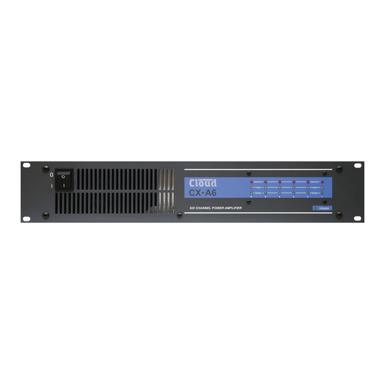
For more detailed information refer to the rear of the manual. General The CX-A6 is a six-channel power amplifier with a maximum output of 120 watts into loads of 4 ohms per channel. The unit features extremely low distortion and low noise together with a high slew rate. - Page 4 CX-A6 I NSTALLATION AND OPERATION MANUAL POWER AMPLIFIER LEVEL CONTROL SOURCE SWITCHES INPUT AMPLFIER INPUT 1 FROM MONO SOURCE SIX CHANNELS DRIVEN FROM ONE MONO SOURCE POWER AMPLIFIER LEVEL CONTROL SOURCE SWITCHES INPUT AMPLFIER INPUT 1 INPUT 2 FROM STEREO SOURCE...
-
Page 5: Output Details
100V Line operation Connecting a CXL-100 100W 100V-line module across an output of the CX-A6 will obtain a 100W 100V-line output from that channel. The CXL-100 has to be mounted externally of the amplifier and 70V or 100V-... -
Page 6: Configuring The Cx-A4 For 100V Line Operation
240 watt 8 ohm outputs. Status Indicators The front panel of the CX-A6 has an array of LED’s that indicate the status of all six channels. The lower green LED illuminates when a signal exceeding 500mW is detected, the yellow 'peak' LED will illuminate when the amplifier output is close to clipping and the top red LED indicates that the protection relay has disconnected the load. -
Page 7: Vca Modules
NSTALLATION AND OPERATION MANUAL VCA Modules A two-channel VCA module is available as a plug-in option for the CX-A6 (see section 13 for installation details) and can be used with either one or two control plates. The unit can operate two channels independently or switched to provide stereo attenuation via one control plate. -
Page 8: Bose Equalisation Modules
EQ: Two 25mm M3 hex spacers. The CX-A6 connectors to install the VCA modules are to the rear of the amplifier on the input PCB clearly marked on the PCB as ‘CON X TO VCA MODULE’ where ‘X’ is 1,2 or 3 see below: - CON 1 = Channel 1&2... -
Page 9: Field Servicing
VCA Module Orientation (Side View) Field Servicing The CX-A6 is ruggedly built and uses proven reliable circuitry. It requires no more than the occasional removal of any dust that may have built up inside the unit as a result of the forced cooling. -
Page 10: General Specifications
CX-A6 I NSTALLATION AND OPERATION MANUAL General Specifications Inputs Balanced via 3 pin XLR type connector. Outputs Binding Posts for flexible cables up to 2.5mm² Protection VI limiting, DC offset, Thermal and Switch-on Delay Status Indicators LED indicators on each channel for Signal, Peak & Protect Cooling Force cooled using a two speed DC fan. -
Page 11: Safety Considerations And Information
Bose is a registered trademark of The Bose Corporation In the interest of continuing improvements cloud electronics limited reserves the right to alter specifications without prior notice. Cloud Electronics Limited 140 Staniforth Road Sheffield S9 3HF England Telephone +44(0) 114 244 7051 Fax +44(0) 114 242 5462 E-mail: Info@cloud.co.uk...
Need help?
Do you have a question about the CX-A6 and is the answer not in the manual?
Questions and answers