Carrier 58MCA Service And Maintenance Instructions
Deluxe multipoise gas-fired condensing furnaces series 111 sizes 040—120
Hide thumbs
Also See for 58MCA:
- Installation, start-up, and operating instructions manual (48 pages) ,
- Service and maintenance instructions (16 pages) ,
- User's information manual (14 pages)
Table of Contents
Advertisement
Service and Maintenance Instructions
NOTE: Read the entire instruction manual before performing any
service or maintenance.
Index
SAFETY CONSIDERATIONS..................................................1-2
PROCEDURE ...........................................................................2
GENERAL......................................................................................2
CARE AND MAINTENANCE................................................2-13
Clean and/or Replace Air Filter............................................2-3
Blower Motor and Wheel Maintenance................................3-4
Clean Burners ........................................................................4-5
Clean Heat Exchangers .........................................................5-8
Primary Heat Exchangers ................................................5-6
Secondary Heat Exchangers................................................6
Flush Collector Box and Drainage System..............................6
Service Hot Surface Ignitor......................................................6
Electrical Controls and Wiring .............................................6-9
Troubleshooting ...................................................................9-12
Check Heat Tape Operation (If Applicable)..........................12
Winterizing..............................................................................13
WIRING DIAGRAM ......................................................14 and 20
Fixed Capacity ........................................................................14
Variable Capacity....................................................................20
TROUBLESHOOTING ..........................................................15-19
Fixed Capacity...................................................................15-17
Variable-Capacity Service Label ......................................18-19
SAFETY CONSIDERATIONS
Installing and servicing heating equipment can be hazardous due to
gas and electrical components. Only trained and qualified person-
nel should install, repair, or service heating equipment.
Untrained personnel can perform basic maintenance functions
such as cleaning and replacing air filters. All other operations must
be performed by trained service personnel. When working on
heating equipment, observe precautions in the literature, on tags,
and on labels attached to or shipped with the unit and other safety
precautions that may apply.
Follow all safety codes, including NFPA 54/ANSI Z223.1-1992,
National Fuel Gas Code. In Canada, refer to the current edition of
Manufacturer reserves the right to discontinue, or change at any time, specifications or designs without notice and without incurring obligations.
Book 1 4
PC 101
Catalog No. 565-904
Tab 6a 8a
For Sizes 040-120, Series 111
A93040
Page
Printed in U.S.A.
58MCA, 58MXA, 58MVP
Deluxe Multipoise Gas-Fired
Condensing Furnaces
®
ama
A PP R O VED
R
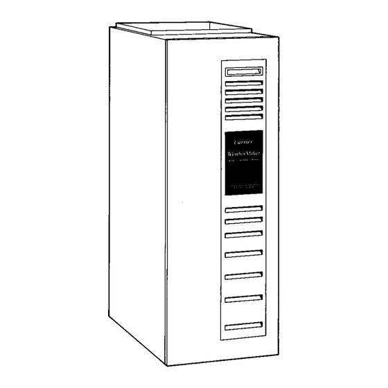
Fig. 1-Multipoise Furnace in Upflow Orientation
the National Standard of Canada CAN/CGA-B-149. Wear safety
glasses and work gloves. Have a fire extinguisher available during
start-up and adjustment procedures and service calls.
Recognize safety information. This is the safety-alert symbol
When you see this symbol on the unit and in instructions or
manuals, be alert to the potential for personal injury.
Understand the signal words DANGER, WARNING, and CAU-
TION. These words are used with the safety-alert symbol. DAN-
GER identifies the most serious hazards which will result in severe
personal injury or death. WARNING signifies hazards which
could result in personal injury or death. CAUTION is used to
identify unsafe practices which would result in minor personal
injury or product and property damage. NOTE is used to highlight
suggestions which will result in enhanced installation, reliability,
or operation.
The ability to properly perform maintenance on this equip-
ment requires certain expertise, mechanical skills, tools, and
equipment. If you do not possess these, do not attempt to
perform any maintenance on this equipment other than those
procedures recommended in the User's Manual. FAILURE
TO FOLLOW THIS WARNING COULD RESULT IN
POSSIBLE DAMAGE TO THIS EQUIPMENT, SERIOUS
PERSONAL INJURY, OR DEATH.
Form 58M-2SM
Pg 1
A93007
.
6-94
Replaces: 58M-1SM
Advertisement
Table of Contents
Troubleshooting

Related Manuals for Carrier 58MCA


Summary of Contents for Carrier 58MCA
-
Page 1: Table Of Contents
58MCA, 58MXA, 58MVP Deluxe Multipoise Gas-Fired Condensing Furnaces Service and Maintenance Instructions For Sizes 040—120, Series 111 NOTE: Read the entire instruction manual before performing any service or maintenance. ® A93040 Index Page SAFETY CONSIDERATIONS..........1-2 A PP R O VED ELECTROSTATIC DISCHARGE (ESD) PRECAUTIONS PROCEDURE ................2... -
Page 2: Electrostatic Discharge (Esd) Precautions Procedure
Never store anything on, near, or in contact with the furnace, such as: 1. Spray or aerosol cans, rags, brooms, dust mops, vacuum cleaners, or other cleaning tools. 2. Soap powders, bleaches, waxes or other cleaning com- pounds, plastic or plastic containers, gasoline, kerosene, cigarette lighter fluid, dry cleaning fluids, or other volatile fluids. -
Page 3: Blower Motor And Wheel Maintenance
Remove bolts holding motor mounts to blower housing and to the control center and transformer. slide motor and mounts out of housing. On fixed-capacity furnaces (58MCA or 58MXA) only, disconnect capacitor 3. Disconnect wires. and ground wire attached to blower housing before remov- a. -
Page 4: Clean Burners
(See Fig. 18.) NOTE: Refer to Table 1 for motor speed lead relocation if leads MANIFOLD MOUNTING were not identified before disconnection. SCREW Table 1—Speed Selector (58MCA or 58MXA Only) COLOR SPEED FACTORY ATTACHED TO Black High... -
Page 5: Clean Heat Exchangers
14. Reinstall burner box pressure tube to gas valve regulator fitting. 15. Reinstall gas supply pipe to gas valve using backup wrench on gas valve to prevent rotation and improper orientation. NOTE: Use propane gas resistant pipe dope to prevent gas leaks. DO NOT use Teflon tape. -
Page 6: Secondary Heat Exchangers
16. Check furnace operation through 2 complete heat operating condensate trap to ensure no condensate leaks occur. If leaks cycles. Look through sight glass in burner enclosure to check are found, correct the problem. burners. Burner flames should be clear blue, almost transpar- 15. - Page 7 3. HORIZONTAL-LEFT installations require the collector box pressure tube to be relocated between the inducer housing and the blower shelf to prevent a trap. Refer to the Installation Instructions for further details. 322093-101 REV. B A94211 Fig. 8—Furnace Pressure and Drain Tubing Diagram (58MCA and 58MXA)
- Page 8 INSTALLATION LEVEL (0") LEVEL (0") This appliance requires a special venting system. Refer to the 1/2" MAX 1/2" MAX installation instructions for parts list and method of installation. Furnace must be installed level, or pitched forward within 1/2 inch of level for proper drainage. Failure will result in equipment or property damage.
-
Page 9: Troubleshooting
Main blower operates at cooling speed for 10 sec, then turns off. 58MCA AND 58MXA FURNACES e. Main blower operates at heating speed for 10 sec, then For an explanation of fault codes, refer to service label located on turns off. - Page 10 A93049 Fig. 13—Field Wiring a. Remove main furnace door. a. Leave 115-v power to furnace turned on. b. Remove blower access panel. b. Remove main furnace door. c. Manually close blower access panel door switch. c. Look into blower access panel sight glass for current LED status.
- Page 11 BLOWER OFF DELAY ADJUSTMENT SWITCH 24V THERMOSTAT TERMINALS TEST/TWIN HUMIDIFIER TERMINAL (24-VAC 0.5 AMP MAX) LED OPERATION & DIAGNOSTIC LIGHT HARNESS CONNECTOR SEC-1 24V TRANSFORMER SEC-2 3-AMP FUSE SPARE 1 COOL BLOWER SPEED HEAT SELECTION TERMINALS SPARE 2 EAC 1 (BLACK) EAC-ELECTRONIC AIR CLEANER TERMINALS (115-VAC 1 AMP MAX) 115-VAC (L1)
-
Page 12: Check Heat Tape Operation (If Applicable)
HOT SURFACE EAC-ELECTRONIC AIR IGNITOR CONNECTOR CLEANER TERMINALS (115-VAC 1 AMP MAX) 115-VOLT CONNECTORS PRESSURE SWITCH CONNECTOR HUM-HUMIDIFIER MAIN BLOWER TERMINAL CONTROL WIRE (24-VAC 0.5 AMP MAX) CONNECTOR 24-VOLT THERMOSTAT TERMINALS TRANSFORMER 24-VOLT CONNECTORS DEHUMIDIFIER (DH) CONNECTOR 3-AMP FUSE STATUS AND DIAGNOSTIC LED LIGHTS AIR CONDITIONING (A/C) SETUP SWITCH... -
Page 13: Winterizing
Step 10—Winterizing Freezing condensate left in the furnace will damage the equipment. If the furnace will be off for an extended period of time in a structure where the temperature will drop to 32°F or below, winterize as follows: 1. Turn off electrical supply to furnace. 2. -
Page 15: Troubleshooting
Briefly short the TEST terminal to the "C" terminal. Status LED will flash code and then turn on the inducer motor, hot surface igniter, blower motor-heat speed, and blower motor-cool speed for 10-15 seconds each. BLOWER OFF DELAY SELECT 320615-102 REV. A A93297 Fig. 19—Service Label for 58MCA and 58MXA... - Page 19 FUSE 1 2 3 4 5 6 7 8 SETUP SW,(SW1-8)
-
Page 20: Wiring Diagram
Copyright 1994 CARRIER Corp. • 7310 W. Morris St. • Indianapolis, IN 46231 35032c Manufacturer reserves the right to discontinue, or change at any time, specifications or designs without notice and without incurring obligations. Book 1 4 PC 101 Catalog No. 565-904 Printed in U.S.A.
Need help?
Do you have a question about the 58MCA and is the answer not in the manual?
Questions and answers