Carrier 58MCA Service And Maintenance Instructions
4-way multipoise fixed-capacity direct-vent condensing gas furnace sizes 040—140, series 131
Hide thumbs
Also See for 58MCA:
- Installation, start-up, and operating instructions manual (48 pages) ,
- Service and maintenance instructions (20 pages) ,
- User's information manual (14 pages)
Table of Contents
Advertisement
Visit www.carrier.com
Service and Maintenance Instructions
NOTE: Read the entire instruction manual before performing any
service or maintenance.
This symbol
indicates a change since the last issue.
Index
SAFETY CONSIDERATIONS..................................................1-2
GENERAL......................................................................................2
CARE AND MAINTENANCE................................................2-11
Cleaning and/or Replacing Air Filter.......................................3
Blower Motor and Wheel Maintenance................................3-4
Cleaning Burners ...................................................................4-5
Cleaning Heat Exchangers ....................................................5-7
Primary Heat Exchangers ................................................5-7
Secondary Heat Exchangers................................................7
Flushing Collector Box and Drainage System ........................7
Servicing Hot Surface Ignitor ...............................................7-8
Electrical Controls and Wiring .............................................8-9
Troubleshooting ...................................................................9-10
Checking Heat Tape Operation (If Applicable) ....................10
Winterizing ........................................................................10-11
WIRING DIAGRAM...................................................................12
SERVICE LABEL .......................................................................13
TROUBLESHOOTING GUIDE ............................................14-15
SAFETY CONSIDERATIONS
Installing and servicing heating equipment can be hazardous due to
gas and electrical components. Only trained and qualified person-
nel should install, repair, or service heating equipment.
Untrained personnel can perform basic maintenance functions
such as cleaning and replacing air filters. All other operations must
be performed by trained service personnel. When working on
heating equipment, observe precautions in the literature, on tags,
and on labels attached to or shipped with the unit and other safety
precautions that may apply.
Follow all safety codes, including NFPA 54/ANSI Z223.1-1996,
National Fuel Gas Code and ANSI/NFPA 90B, Installation Stan-
dards, Warm Air Heating and Air Conditioning Systems. In
Canada, refer to the current edition of the National Standard of
Manufacturer reserves the right to discontinue, or change at any time, specifications or designs without notice and without incurring obligations.
Book 1 4
PC 101
Catalog No. 565-879
Tab 6a 8a
Direct-Vent Condensing Gas Furnace
For Sizes 040-140, Series 131
A93040
Page
Printed in U.S.A.
Form 58MCA-4SM
4-Way Multipoise Fixed-Capacity
®
ama
A PP R O VED
R
SM
As an ENERGY STAR
Partner, Carrier Corporation
has determined that this prod-
uct
meets
the
ENERGY
STAR guidelines for energy
efficiency.
CERTIFICATION OF MANUFACTURING SITE
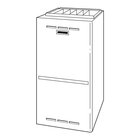
Fig. 1-Multipoise Furnace in Upflow Orientation
Canada CAN/CGA-B-149. Wear safety glasses and work gloves.
Have a fire extinguisher available during start-up and adjustment
procedures and service calls.
Recognize safety information. This is the safety-alert symbol
When you see this symbol on the unit and in instructions or
manuals, be alert to the potential for personal injury.
Understand the signal words DANGER, WARNING, and CAU-
TION. These words are used with the safety-alert symbol. DAN-
GER identifies the most serious hazards which will result in severe
personal injury or death. WARNING signifies hazards which
could result in personal injury or death. CAUTION is used to
identify unsafe practices which would result in minor personal
injury or product and property damage. NOTE is used to highlight
suggestions which will result in enhanced installation, reliability,
or operation.
Pg 1
58MCA
A93278
11-96
Replaces: 58MCA-3SM
.
Advertisement
Table of Contents
Troubleshooting

Subscribe to Our Youtube Channel
Related Manuals for Carrier 58MCA


Summary of Contents for Carrier 58MCA
-
Page 1: Table Of Contents
4-Way Multipoise Fixed-Capacity Direct-Vent Condensing Gas Furnace ® A93040 A PP R O VED Page As an ENERGY STAR Partner, Carrier Corporation has determined that this prod- meets ENERGY STAR guidelines for energy efficiency. CERTIFICATION OF MANUFACTURING SITE Fig. 1—Multipoise Furnace in Upflow Orientation Canada CAN/CGA-B-149. -
Page 2: Electrostatic Discharge (Esd) Precautions
The ability to properly perform maintenance on this equip- ment requires certain expertise, mechanical skills, tools, and equipment. If you do not possess these, do not attempt to perform any maintenance on this equipment other than those procedures recommended in the User’s Manual. FAILURE TO FOLLOW THIS WARNING COULD RESULT IN POSSIBLE DAMAGE TO THIS EQUIPMENT, SERIOUS PERSONAL INJURY, OR DEATH. -
Page 3: Cleaning And/Or Replacing Air Filter
FILTER FILTER RETAINER SUPPORT Fig. 3—Bottom Filter Arrangement Step 1—Cleaning and/or Replacing Air Filter The air filter arrangement may vary depending on the application or orientation. Never operate unit without a filter or with the blower access panel removed. Failure to follow this warning could result in a fire or personal injury. -
Page 4: Cleaning Burners
11. Reinstall condensate trap and tubing if previously removed. a. Reinstall condensate trap in hole in blower shelf. b. Connect condensate trap drain tubes. See Fig. 8 or tubing diagram on main furnace door for proper tube location. (1.) Connect 1 tube (blue or blue and white striped) from collector box. -
Page 5: Cleaning Heat Exchangers
Never use matches, candles, flame, or other sources of ignition to check for gas leakage. Use a soap-and-water solution. Failure to follow this warning could result in a fire, personal injury, or death. 19. Replace main furnace door. Step 4—Cleaning Heat Exchangers The following items should be performed by a qualified service technician. -
Page 6: Installation
This appliance requires a special venting system. Refer to the installation instructions for parts list and method of installation. Furnace must be installed level, or pitched forward within 1/2 inch of level for proper drainage. Failure will result in equipment or property damage. -
Page 7: Secondary Heat Exchangers
BURNER FLAME MANIFOLD Fig. 9—Burner Flame Never use matches, candles, flame, or other sources of ignition to check for gas leakage. Use a soap-and-water solution. Failure to follow this warning could result in a fire, personal injury, or death. 18. Replace main furnace door. SECONDARY HEAT EXCHANGERS NOTE: The condensing side (inside) of the secondary heat exchangers CANNOT be serviced or inspected. -
Page 8: Electrical Controls And Wiring
Allow ignitor to cool before removal. Normal operation temperatures exceed 2000°F. a. Do not remove ignitor from retainer while assembly is in furnace. Using a small pocket straight-blade screwdriver, slowly pry 1 edge of the spring retainer from burner box housing. -
Page 9: Component Test Sequence
TEST/TWIN 3-AMP FUSE 115-VAC (L1) POWER SUPPLY HOT SURFACE IGNITOR CONNECTOR NOTE: If the polarity is not correct, the STATUS LED on the control center will flash rapidly and prevent the furnace from operating. The control system also requires an earth ground for proper operation of the control center and flame sensing. -
Page 10: Checking Heat Tape Operation (If Applicable)
NOTE: Leave blower access panel installed to maintain power to control center to view current LED status. 4. BRIEFLY remove either wire from the main limit switch until the LED goes out, then reconnect it. Make sure limit switch wire does not contact any metallic component such as the gas valve. - Page 11 A94208 A94209 Fig. 14—Inducer Housing Drain Tube Fig. 15—Funnel in Drain and Antifreeze Running Through Trap...
-
Page 12: Wiring Diagram
TRAN... -
Page 13: Service Label
SERVICE LED CODE STATUS CONTINUOUS OFF - Check for 115VAC at L1 and L2, and 24VAC at SEC-1 and SEC-2. CONTINUOUS ON - Control has 24V power. RAPID FLASHING - Line voltage (115V) polarity reversed. If twinned, refer to twinning kit instructions. EACH OF THE FOLLOWING STATUS CODES IS A TWO DIGIT NUMBER WITH THE FIRST DIGIT DETERMINED BY THE NUMBER OF SHORT FLASHES AND THE SECOND DIGIT BY THE NUMBER OF LONG FLASHES. -
Page 16: Service Training
CALL FOR FREE CATALOG 1-800-962-9212 [ ] Packaged Service Training Copyright 1996 CARRIER Corp. • 7310 W. Morris St. • Indianapolis, IN 46231 Manufacturer reserves the right to discontinue, or change at any time, specifications or designs without notice and without incurring obligations.
Need help?
Do you have a question about the 58MCA and is the answer not in the manual?
Questions and answers