Toshiba Satellite A350 Series User Manual
Toshiba satellite notebook user's manual
Hide thumbs
Also See for Satellite A350 Series:
- Maintenance manual (278 pages) ,
- Manual del usuario (238 pages) ,
- User manual (236 pages)
Table of Contents
Advertisement
Quick Links
Advertisement
Table of Contents

Related Manuals for Toshiba Satellite A350 Series


Summary of Contents for Toshiba Satellite A350 Series
- Page 1 TOSHIBA Satellite A350/ Satellite A350D series User's Manual...
-
Page 2: Copyright
Copyright © 2008 by TOSHIBA Corporation. All rights reserved. Under the copyright laws, this manual cannot be reproduced in any form without the prior written permission of TOSHIBA. No patent liability is assumed, with respect to the use of the information contained herein. -
Page 3: Safety Instructions
Dolby and the double-D symbol are trademarks of Dolby Laboratories. Dolby Home Theater is a trademark of Dolby Laboratories. ExpressCard is a trademark of PCMCIA HDMI, the HDMI logo and High-Definition Multimedia Interface are trademarks or registered trademarks of HDMI Licensing LLC. LabelFlash is trademark of YAMAHA Corporation. -
Page 4: When Using Your Computer
When using your computer Do not operate your portable computer for an extended period of time with the base resting directly on your body. With extended operation, heat can potentially build up in the base. Allowing sustained contact with the skin could cause discomfort or, eventually, a burn. -
Page 5: Fcc Information
Only peripherals complying with the FCC class B limits may be attached to this equipment. Operation with non-compliant peripherals or peripherals not recommended by TOSHIBA is likely to result in interference to radio and TV reception. Shielded cables must be used between the external devices and the computer’s external monitor port, Universal Serial Bus... -
Page 6: Eu Declaration Of Comformity
Note that Canadian Department of Communications (DOC) regulations provide, that changes or modifications not expressly approved by TOSHIBA Corporation could void your authority to operate this equipment. This Class B digital apparatus meets all requirements of the Canadian Interference-Causng Equipment Regulations. -
Page 7: Region Selection
Network Compatibility Statement This product is designed to work with, and is compatible with the following networks. It has been tested to and found to conform with the additional requirements conditional in EG 201 121. Germany ATAAB AN005, AN006, AN007, AN009, AN010 and DE03, 04, 05, 08, 09, 12, 14, 17 Greece ATAAB AN005, AN006 and GR01, 02, 03, 04... -
Page 8: Telephone Company Procedures
FCC. In the event repairs are ever needed on your modem, they should be performed by TOSHIBA Corporation or an authorized representative of TOSHIBA Corporation. -
Page 9: Instructions For Ic Cs-03 Certified Equipment
Disconnection If you should ever decide to permanently disconnect your modem from its present line, please call the telephone company and let them know of this change. Fax branding The Telephone Consumer Protection Act of 1991 makes it unlawful for any person to use a computer or other electronic device to send any message via a telephone fax machine unless such a message clearly contains in a margin at the top or bottom of each transmitted page, or on the first page of... -
Page 10: Notes For Users In Australia And New Zealand
2. The user manual of analog equipment must contain the equipment’s Ringer Equivalence Number (REN) and an explanation notice similar to the following: The Ringer Equivalence Number (REN) of the modem can vary - for the REN, please refer to the modem's label. The Ringer Equivalence Number (REN) assigned to each terminal device provides an indication of the maximum number of terminals allowed to be connected to a telephone interface. - Page 11 Notes for use of this device in New Zealand ■ The grant of a Telepermit for a device in no way indicates Telecom acceptance of responsibility for the correct operation of that device under all operating conditions. In particular the higher speeds at which this modem is capable of operating depend on a specific network implementation which is only one of many ways of delivering high quality voice telephony to customers.
-
Page 12: General Conditions
■ When used in Auto Answer mode, the S0 register must be set with to a value of either 3 or 4. This ensures: ■ a person calling your modem will hear a short burst of ringing before the modem answers. This confirms that the call has been successfully switched through the network. -
Page 13: Following Information Is Only For Eu-Member States
For more detailed information about the collection and recycling programmes available in your country, please visit our website (http://eu.computers.toshiba-europe.com) or contact your local city office or the shop where you purchased the product. Disposal of batteries and/or accumulators The crossed out wheeled dust bin symbol indicates that batteries and/or accumulators must be collected and disposed of separately from household waste. - Page 14 ENERGY STAR logo on the computer and the following information applies. TOSHIBA is a partner in the ENERGY STAR Program and has designed this computer to meet the latest ENERGY STAR guidelines for energy efficiency.
- Page 15 Optical disc drive safety instructions ■ The drive employs a laser system. To ensure proper use of this product, please read this instruction manual carefully and retain for future reference. Should the unit ever require maintenance, contact an authorized service location. ■...
- Page 16 HLDS GSA-T50N/GSA-T50F Location of the required label COMPLIES WITH FDA RADIATION PERFORMANCE STANDARDS, 21 CFR SUBCHAPTER J. MANUFACTURED Hitachi-LG Data Storage, Inc. 22-23, Kaigan 3-chome, Minato-Ku, Tokyo, 108-0022 Japan Pioneer DVR-TD08TBM/DVR-TD08TBF Location of the required label COMPLIES WITHFDA RADIATION PERFORMANCE STANDARDS, 21 CFR SUBCHAPTER J MANUFACTURED PIONEER CORPORATION...
- Page 17 PRODUCT IS CERTIFIED BY THE MANUFACTURER TO COMPLY WITH DHHS RULES 21 CFR CHAPTER 1, SUBCHAPTER J, APPLICABLE AT THE DATE OF MANUFACTURE. MANUFACTURED Toshiba Samsung Storage Technology Korea Corporation 416, Maetan-3Dong, Yeongtong-Gu, Suwon City, Gyeonggi-Do, 443-742, Korea User’s Manual...
-
Page 18: International Precautions
International precautions CAUTION: This appliance contains a laser system and is classified as a “CLASS 1 LASER PRODUCT.” To use this model properly, read the instruction manual carefully and keep this manual for your future reference. In case of any trouble with this model, please contact your nearest “AUTHORIZED service station.”... -
Page 19: Important Notice
Dispose of used batteries according to the manufacturer’s instructions. Use only the battery pack that came with the computer or an optional battery pack. Use of wrong battery could damage your computer. TOSHIBA assumes no liability for any damage in such case. User’s Manual... -
Page 20: Table Of Contents
Table of Contents Copyright..........ii Disclaimer . - Page 21 Special features ......... 1-11 TOSHIBA Value Added Package ......1-13 Utilities and Applications.
- Page 22 TOSHIBA support ........
- Page 23 HDD drive capacity ........10-3 LCD .
- Page 24 TECRA M7 Glossary User’s Manual xxiv...
-
Page 25: Preface
This manual tells how to set up and begin using your TOSHIBA Satellite A350/Satellite A350D series computer. It also provides detailed information on configuring your computer, basic operations and care, using optional devices and troubleshooting. -
Page 26: Conventions
Preface Chapter 5, Keyboard, describes special keyboard functions including the keypad overlay and hot keys. Chapter 6, Power and Power-up Modes, gives details on the computer’s power resources and battery save modes. Chapter 7, HW Setup and Passwords, explains how to configure the computer using the HW Setup program. - Page 27 Preface When procedures require an action such as clicking an icon or entering text, the icon's name or the text you are to type in is represented in the typeface you see to the left. Display Names of windows or icons or text generated by the computer that appear on its display screen are presented in the type face you see to the left.
-
Page 28: General Precautions
General Precautions TOSHIBA computers are designed to optimize safety, minimize strain and withstand the rigors of portability. However, certain precautions should be observed to further reduce the risk of personal injury or damage to the computer. Be certain to read the general precautions below and to note the cautions included in the text of the manual. -
Page 29: Heat Injury
General Precautions Heat injury ■ Avoid prolonged physical contact with the computer. If the computer is used for long periods, its surface can become very warm. While the temperature will not feel hot to the touch, if you maintain physical contact with the computer for a long time, for example if you rest the computer on your lap or if you keep your hands on the palm rest, your skin might suffer a low-heat injury. -
Page 30: Introduction
Some of the features described in this manual may not function properly if you use an operating system that was not pre-installed by TOSHIBA. Equipment checklist Carefully unpack your computer, taking care to save the box and packaging materials for future use. - Page 31 (This manual) SD Memory Card Format Utility and other SD functions are packaged into TOSHIBA SD Memory Utilities. When uninstalling the SD utilities, click Start -> Control Panel -> Uninstall a program, and select TOSHIBA SD Memory Utilities. Documentation ■...
-
Page 32: Features
Your computer is equipped with one processor and processor type varies depending on model. To check which type of processor is included in your model, open the TOSHIBA PC Diagnostic Tool Utility by clicking Start -> All programs -> TOSHIBA -> Utilities -> TOSHIBA PC diagnostic Tool. - Page 33 Introduction ■ ® Maximum size of memory can be installed on Mobile Intel GL40 Express Chipset models is 4GB. ■ ® PC2-6400 memory module works as PC2-5300 speed on Mobile Intel GL40 Express Chipset models. ■ PC2-6400 memory module works as PC2-5300 speed on AMD Athlon 64x2 Dual-Core Processor.
-
Page 34: Pointing Device
Introduction Disks Hard disk drive or This computer is equipped with the following types of hard disk drive(HDD). The capacity of Solid state drive each hard disk drive model is different. ■ ■ 120GB ■ 160GB ■ 250GB ■ 320GB ■... - Page 35 Introduction AC adaptor The AC adaptor provides power to the system and recharges the batteries when they are low. It comes with a detachable power cord which will either have a 2-pin or 3-pin plug enclosure. As the AC adaptor is universal, it can receive a range of AC voltages from 100 to 240 volts, however you should note that the output current varies among different models.
- Page 36 Introduction Multimedia Sound system The integrated sound system provides support for the computer's internal speakers and microphone, also allowing an external microphone and headphones to be connected via the appropriate jacks. Web Camera Web Camera is a device that allows you to record video or take photographs with your computer.
- Page 37 Introduction Infrared receiver This is a sensor window that receives signals window from the remote controller which is provided with your computer. Models which do not include a remote controller are not equipped with an infrared receiver so the computer cannot be operated with a remote controller.
- Page 38 Introduction ■ The transmission speed over the wireless LAN and the distance over which wireless LAN can reach may vary depending on surrounding electromagnetic environment, obstacles, access point design and configuration, and client design and software/hardware configurations. The Transmit Rate (at X Mbit/s) is the theoretical maximum speed under the IEEE802.11 (a/b/g/n) standards.
- Page 39 Introduction Optical disc drive DVD Super Multi The drive reads DVD-ROM's at a maximum 8x drive speed and CD-ROM's at a maximum 24x speed, and writes CD-R's at up to 24x speed, CD-RW's at up to 24x speed, DVD-R's and DVD+R's at up to 8x speed, DVD-RW's and DVD+RW's at up to 8x speed, DVD-R (Dual layer) at up to 6x speed, DVD+R (Double Layer) at up to 6x speed and...
-
Page 40: Special Features
Special features The following features are either unique to TOSHIBA computers or are advanced features which make the computer more convenient to use. Access each function using the following procedures. *1 To access the Power Options, click Start -> Control Panel -> System and Maintenance ->... - Page 41 Introduction Keypad overlay A ten-key numeric keypad is integrated into the keyboard. Please refer to the Keypad overlay section in Chapter 5, Keyboard, for information on using this feature. Power on password Two levels of password security, supervisor and user, are available to prevent unauthorized access to your computer.
-
Page 42: Toshiba Value Added Package
TOSHIBA Value Added Package This section describes the TOSHIBA Component features pre-installed on the computer. TOSHIBA Power TOSHIBA Power Saver provides you with the... -
Page 43: Utilities And Applications
Fingerprint security cannot be used in models that do not have a fingerprint module installed. TOSHIBA Face TOSHIBA Face Recognition uses a face Recognition verification library to verify the face data of users when they log in to Windows. If the verification is successful, the user will be logged into Windows automatically. - Page 44 To start the utility, click the Windows Start button, point to All Programs, click TOSHIBA, click Utilities, and select HWSetup icon. TOSHIBA ConfigFree TOSHIBA ConfigFree is a suite of utilities that improve the ease and control of communication devices and network connections, help in the...
- Page 45 In order to determine if the optical disc drive installed in your computer supports Labelflash follow the steps as detailed below: 1. Click Start -> All Programs -> DVD MovieFactory for TOSHIBA -> Ulead DVD MovieFactory for TOSHIBA Launcher to launch DVD MovieFactory.
-
Page 46: Options
Introduction CD/DVD Drive The CD/DVD Drive Acoustic Silencer utility Acoustic Silencer allows you to configure the read speed at which the optical disc drive will operate. In use you can select either Normal Mode, which will operate the drive at its maximum speed for quick data access, or Quiet Mode, which operates the drive at single speed for audio CD playback and which can lessen the operational noise. -
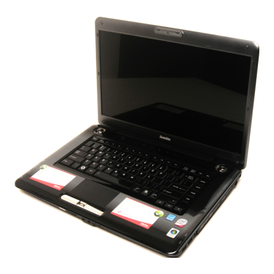
Page 47: Chapter 2 The Grand Tour
Chapter 2 The Grand Tour This chapter identifies the various components of your computer. Become familiar with each component before you operate the computer. Front with the display closed The following figure shows the computer’s front with its display panel in the closed position. - Page 48 The Grand Tour ■ ® Turn Wi-Fi and Bluetooth functionalities off when near a person who may have a cardiac pacemaker implant or other medical electric device. Radio waves may affect pacemaker or medical device operation, possibly resulting in serious injury. Follow the instruction of your medical device when using any Wi-Fi or Bluetooth functionality.
-
Page 49: Left Side
The Grand Tour Headphone (S/PDIF) A 3.5 mm mini headphone jack that lets you jack connect digital speakers or a stereo headphone (16 ohm minimum). When you connect a digital speaker or headphones, the internal speaker is automatically disabled. This jack can be used also as S/PDIF jack and enables connection of optical digital correspondence apparatus. - Page 50 The Grand Tour Vide-out port Plug a 4-pin S-Video connector into this port. HDMI out port HDMI out port can connect with Type A connector HDMI cable.One HDMI cable can send video and audio signals. In addition to this, it can send and receive control signals. By connecting a TV which supports HDMI Control to this port, the remote control for the connected TV can be used to operate some of...
-
Page 51: Right Side
The Grand Tour ExpressCard slot This slot allows you to install a single ExpressCard device. Slim size remote controller is contained in the ExpressCard slot. Some models are equipped with a Slim size remote controller. Keep foreign metal objects, such as screws, staples and paper clips, out of the ExpressCard slot and PC Card slot. - Page 52 The Grand Tour Universal Serial Bus Two Universal Serial Bus ports, which comply (USB 2.0) port with the USB 2.0 standard, are provided on the right side of the computer. Modem jack The modem jack allows you use to attach a modular cable in order to connect the internal modem directly to a telephone line.
-
Page 53: Back Side
The Grand Tour Back side Figure 2-4 shows the computer’s back side. Figure 2-4 The computer’s back side. Underside The following figure shows the underside of the computer. You should ensure that the display is closed before the computer is turned over to avoid causing any damage. -
Page 54: Front With The Display Open
The Grand Tour Battery release latch Slide and hold this latch into its 'Unlock' position in order to release the battery pack ready for removal. For more detailed information on removing the battery pack please refer to Chapter 6, Power and Power-up Modes. - Page 55 The Grand Tour Display hinge The display hinge allows the display panel to be position at a variety of easy-to-view angles. Stereo speakers The speakers emit sound generated by your software as well as audio alarms, such as low battery condition, generated by the system. Keep foreign objects out of the speakers.
- Page 56 The Grand Tour System indicators These LED indicators allow you to monitor the status of various computer functions and are described in more detail within the System indicators section. Web Camera Web Camera is a device that allows you to record video or take photographs with your computer.
-
Page 57: Function Button
CD/DVD button Press this button to launch an application program that allows Windows Media Player / TOSHIBA DVD PLAYER. Play/Pause button Press this button to begin playing an audio CD, a DVD movie or digital audio files. This button also acts as a Pause button. -
Page 58: System Indicators
The Grand Tour System indicators The LED system indicators for specific computer operations glow when those operations are in progress. Figure 2-8 System indicators DC IN The DC IN indicator normally glows white when power is being correctly supplied from the AC power adaptor. - Page 59 The Grand Tour CAPS LOCK indicator Figure 2-9 Keypad indicators CAPS LOCK This indicator glows green when letter keys are locked into their uppercase format. Arrow Mode When the Arrow Mode indicator lights green, you can use the gray labeled keys on the keypad overlay as cursor keys.
-
Page 60: Optical Disc Drives
This section describes the types of writable CD/DVD discs. Check the specifications of your drive to see the types of discs it can write. Use TOSHIBA Disc Creator to write compact discs. Please refer to Chapter 4, Operating Basics for further information. -
Page 61: Remote Controller
The Grand Tour DVDs ■ DVD-R, DVD+R, DVD-R (Dual Layer) and DVD+R (Double Layer) discs can be written only once. The recorded data cannot be erased or changed. ■ DVD-RW, DVD+RW and DVD-RAM discs can be recorded more than once. Some types and formats of DVD-R (Dual Layer) and DVD+R (Double Layer) discs may be unreadable. -
Page 62: Slim Size Remote Controller
The Grand Tour Slim Size Remote Controller Brightness up Brightness down CD/DVD Power DVD Menu Volume + Illumination On/Off Arrows Volume - Back More info Mute Rewind Play/Pause Fast Forward Start Stop Skip Replay Figure 2-10 Slim Size Remote Controller CD/DVD Pressing this button will launch an application program that allows you to watch... - Page 63 The Grand Tour Power Starts or terminates the operating system. This button functions like the Power button of your computer. By default, the Sleep Mode is equivalent to the Power Off state of yourcomputer. To change the setting, click Start, select Control panel ->...
-
Page 64: Using The Remote Controller
The Grand Tour Stop Stops the media currently playing. Skip Moves media forward (30 seconds for videos, one music track or one DVD chapter). Using the Remote Controller Some computers include a remote control unit, which allows you to control some of your computer’s functions from a distant location. -
Page 65: Installing/Removing Batteries
The Grand Tour Even if within the effective scope as described above, the remote control may malfunction or not work correctly in the following cases. ■ When an obstacle stands between the infrared receiver window of your computer and the Remote Controller. ■... -
Page 66: Installing The Battery
The Grand Tour Type of battery that can be used for the Remote Controller When the batteries shipped with the Remote Controller are discharged, replace them with commercially available CR2016 Lithium batteries. Other types or battery should not be used. Slim size remote controller Installing the battery 1. -
Page 67: Placing Slim Size Remote Controller
The Grand Tour Battery Stopper Figure 2-15 Removing the batteries 3. Insert the battery in place. Be sure to place the batteries with correct polarities. Press the battery down to the stopper then push it forward to fit into the battery case. 4. -
Page 68: Ac Adaptor
The Grand Tour ExpressCard slot Slim size remote controller Figure 2-17 Removing a Slim size remote controller AC adaptor The AC adaptor can automatically adjust to any voltage ranging from 90 to 264 volts and to a frequency of either 47 or 63 hertz, enabling you to use this computer in almost any country/region. - Page 69 Always use the TOSHIBA AC adaptor that was included with your computer, or use AC adaptors specified by TOSHIBA to avoid any risk of fire or other damage to the computer. Use of an incompatible AC adaptor could cause fire or damage to the computer possibly resulting in serious injury.
-
Page 70: Chapter 3 Getting Started
Chapter 3 Getting Started This chapter provides basic information to start using your computer. It covers the following topics: ■ If the battery pack is not pre-installed in the computer that you purchased, please install the battery pack before you start using the computer. -
Page 71: Connecting The Ac Adaptor
Getting Started ■ Use a anti-virus software and make sure it is updated regularly. ■ Never format storage media without checking its content - formatting destroys all stored data. ■ It is a good idea to periodically back up the internal hard disk drive or other main storage device to external media. - Page 72 ■ Always use the TOSHIBA AC adaptor that was included with your computer or use AC adaptors specified by TOSHIBA to avoid any risk of fire or other damage to the computer. Use of an incompatible AC adaptor could cause fire or damage to the computer possibly resulting in serious injury.
- Page 73 Getting Started 1. Connect the power cord to the AC adaptor. Figure 3-1 Connecting the power cord to the AC adaptor (2-pin plug) Figure 3-2 Connecting the power cord to the AC adaptor (3-pin plug) Either a 2-pin or 3-pin adaptor/cord will be included with the computer depending on the model.
-
Page 74: Opening The Display
Getting Started Opening the display The display panel can be opened to a wide range of angles for optimal viewing. While holding down the palm rest with one hand so that the main body of the computer is not raised, slowly lift the display panel - this will allow the angle of the display panel to be adjusted to provide optimum clarity. -
Page 75: Turning On The Power
Getting Started ■ As the display panel cannot be flipped to180 degrees, please be careful of the angle when flipping open the display panel. ■ Be careful not to open the display panel too far as this could put stress on the display panel’s hinges and cause damage. -
Page 76: Starting Up For The First Time
Getting Started 1. Open the computer's display panel. 2. Press the computer's power button. Power button Figure 3-5 Turning on the power Starting up for the first time ® The Microsoft Windows Vista Startup Screen will be the first screen displayed when you turn on the power. -
Page 77: Hibernation Mode
Getting Started ■ Make sure the Hard Disk Drive indicator is off. If you turn off the power while a disk (disc) is being accessed, you may lose data or damage the disk. ■ Never turn off the power while an application is running. Doing so could cause loss of data. -
Page 78: Starting Hibernation Mode
Getting Started Starting Hibernation Mode You can also enable Hibernation Mode by pressing FN + F4 - please refer to Chapter 5, Keyboard, for further details. To enter Hibernation Mode, follow the steps below. 1. Click Start. 2. Click the arrow button ( ) in the power management buttons ) and select Hibernate from the menu. - Page 79 Getting Started ■ Before entering Sleep Mode, be sure to save your data. ■ Do not install or remove a memory module while the computer is in Sleep Mode. The computer or the memory module could be damaged. ■ Do not remove the battery pack while the computer is in Sleep Mode (unless the computer is connected to an AC power source).
-
Page 80: Restarting The Computer
Getting Started ■ Close the display panel. Please note that this feature must be enabled within the Power Options (to access it, click Start -> Control Panel -> System and Maintenance -> Power Options). ■ Press the power button. Please note that this feature must be enabled within the Power Options (to access it, click Start ->... - Page 81 Getting Started System Recovery Options The System Recovery Options feature is installed on the hard disk when shipped from the factory. The System Recovery Options menu includes tools to repair startup problems, run diagnostics or restore the system. See the Windows Help and Support content for more information about Startup Repair.
- Page 82 Getting Started A recovery image of the software on your computer is stored on the hard disk drive, and can be copied to DVD media by using the following steps: 1. Select either blank DVD media. 2. The application will allow you to choose from a variety of different media onto which the recovery image can be copied including DVD-R, DVD-R DL, DVD-RW, DVD+R, DVD+R DL and DVD+RW.
- Page 83 Press the F9 key to set to default settings, and select the Yes. ■ When the "In Touch with Tomorrow TOSHIBA" prompt appears, press the F12 key to display the Boot menu. Continue with step 3. 3. Use the up and down cursors key to select the CD-ROM icon from the menu.
-
Page 84: Chapter 4 Operating Basics
Chapter 4 Operating Basics This chapter describes the basic operations of your computer, highlights the precautions that should be taken when using it. Using the Touch Pad To use the Touch Pad, simply touch and move your fingertip across it in the direction you want the on-screen pointer to go. -
Page 85: Using The Fingerprint Sensor
Operating Basics You can also tap the Touch Pad to perform functions similar to those of the left button on a standard mouse. Click: Tap once Double-click: Tap twice Drag and drop: Tap to select the item(s) you want to move, leave your finger on the Touch Pad after the second tap and then move the item(s) to their new destination. -
Page 86: Points To Note About The Fingerprint Sensor
Operating Basics The following illustrations show the recommended way to swipe your finger over the fingerprint sensor. Sensor Sensor Figure 4-2 Swipe the finger ■ Avoid swiping with your finger stiff or pressed too hard onto the sensor, and take care to ensure that the center of the fingerprint is touching the sensor before swiping. -
Page 87: Fingerprint Registration
Operating Basics ■ Clean the sensor with a lint-free cloth - do not use detergent or any other chemicals to clean the sensor. ■ Avoid the following finger conditions for enrollment or recognition as they may result in fingerprint enrollment errors or a drop in the fingerprint recognition success rate ■... - Page 88 Operating Basics ■ In use, the fingerprint authentication system will use the same username and password as defined within the Windows operating system. If no Windows password has been configured, you must do this before starting the fingerprint registration process. ■...
-
Page 89: How To Delete The Fingerprint Data
Toshiba does not guarantee that the fingerprint sensor will recognize the enrolled user or accurately screen out unauthorized users at all times. Toshiba is not liable for any failure or damage that might arise out of the use of this fingerprint recognition software or utility. -
Page 90: Points To Note About The Fingerprint Utility Software
Operating Basics Points to note about the Fingerprint Utility software You are able to backup saved fingerprint data and information within the PasswordBank by using the Import or Export User Data facility under the fingerprint management software. However, please be aware that any encrypted files cannot be backup within FileSafe using this function - in these instances it is recommended that you backup these files to external media using standard file copy processes. - Page 91 Operating Basics ■ You must ensure that you use the TOSHIBA Password Utility to register a User Password before using the Fingerprint Pre-OS Authentication and its extended function to allow fingerprints to be used to access the computer when it is turned on.
-
Page 92: Usb Sleep And Charge Function
TOSHIBA does not guarantee that the fingerprint utility technology will be completely secure or error-free, or that it will accurately screen out unauthorized users at all times. TOSHIBA is not liable for any failure or damage that might arise out of the use of the fingerprint software. -
Page 93: Using Optical Disk Drives
Operating Basics However, the USB Sleep and Charge function may not work with certain external devices even if they are compliant with the USB specification. In those cases, turn the power of the computer ON to charge the device. ■ The USB Sleep and Charge function only works for compatible ports. -
Page 94: Loading Discs
Operating Basics Use the DVD playback application to view DVD-Video discs. Loading discs To load CD/DVD's, follow the steps as listed below and refer to figures 4-4 to 4-6. 1. When the computer's power is on, press the eject button to open the disc tray slightly. - Page 95 Operating Basics 3. Lay the CD/DVD, label side up, in the disc tray. Figure 4-5 Inserting a CD/DVD When the disc tray is fully opened, the edge of the computer will extend slightly over the area where you insert the media. Therefore, when loading a CD or DVD, you will need to turn it slightly at an angle when you place it in the disc tray.
-
Page 96: Removing Discs
Operating Basics Removing discs To remove CD/DVD's, follow the steps as listed below. Do not press the eject button while the computer is accessing the media in the drive, instead wait for the indicator to go out before you open the disc tray. -
Page 97: Function Button
This section describes about Function button. Six buttons are provided with some models. Figure 4-8 Function button Icon Function button *CD/None Mute Mute Mute CD/DVD Launch TOSHIBA Launch Windows DVD PLAYER Media Player Play/Pause Play/Pause Play/Pause Stop Stop Stop Previous... -
Page 98: Writng Cd/Dvd On Dvd Super Multi Drives
CD-R/RW media cannot be accessed using the Create CD/DVD option in Media Center. ■ To write data to CD-R/-RW media, use the TOSHIBA Disc Creator feature that is installed on your computer. When writing information to media using an optical drive, you should always ensure that you connect the AC adaptor to a live power socket. - Page 99 Operating Basics CD-R: TAIYO YUDEN CO., Ltd. MITSUBISHI KAGAKU MEDIA CO., LTD. Ricoh Co., Ltd. Hitachi Maxell,Ltd. CD-RW: (Multi-Speed and High-Speed) MITSUBISHI KAGAKU MEDIA CO., LTD. Ricoh Co., Ltd. CD-RW: (Ultra-Speed) MITSUBISHI KAGAKU MEDIA CO., LTD. DVD-R: DVD Specifications for Recordable Disc for General Version 2.0 TAIYO YUDEN Co.,Ltd.
- Page 100 Operating Basics DVD+RW: Ricoh Co., Ltd. (for 2.4x, 4x and 8x speed media) MITSUBISHI KAGAKU MEDIA CO., LTD. (for 2.4x, 4x and 8x speed media) DVD-RAM: DVD Specifications for DVD-RAM Disc for Version 2.0, Version 2.1 or Version 2.2 Matsushita Electric Industrial Co.,Ltd. (for 3x and 5x speed media) Hitachi Maxell,Ltd.
-
Page 101: When Writing Or Rewriting
CD/DVD - do not try to write from shared devices such as a server or any other network device. ■ Writing with software other than TOSHIBA Disc Creator has not been confirmed, therefore operation with other software applications cannot be guaranteed. -
Page 102: Toshiba Disc Creator
TOSHIBA Disc Creator Please be aware of the following limitations when you use the TOSHIBA Disc Creator: ■ DVD Video cannot be created using TOSHIBA Disc Creator. - Page 103 CD Player' function to record music to DVD-R, DVD-R (Dual Layer), DVD-RW, DVD+R, DVD+R (Double Layer) or DVD+RW media. ■ Do not use the 'Disc Backup' function of TOSHIBA Disc Creator in order to copy DVD Video or DVD-ROM material that has copyright protection. ■...
-
Page 104: Data Verification
Simplified steps for making a Labelflash DVD: 1. Insert a Labelflash disc in optical disc drive. Set PRINTING SIDE for underside. 2. Click Start -> All Programs -> DVD MovieFactory for TOSHIBA -> Ulead DVD MovieFactory for TOSHIBA Lancher to launch DVD MovieFactory. -
Page 105: How To Learn More About Ulead Dvd Moviefactory
How to make a DVD-Video Method 1: Simplified steps for making a DVD-Video from video data captured from a DV-Camcorder: 1. Click Start -> All Programs -> DVD MovieFactory for TOSHIBA -> Ulead DVD MovieFactory for TOSHIBA Launcher to launch DVD MovieFactory. - Page 106 Operating Basics Important information for use Note the following limitations when you write Video DVD: 1. Editing digital video ■ Log in with Administrator rights to use DVD MovieFactory. ■ Make sure that your computer is running on AC power when using DVD MovieFactory.
-
Page 107: Toshiba Dvd Player
If you use an over-used rewritable disc, the full formatting might be locked. Please use a brand new disc. TOSHIBA DVD Player Please be aware of the following limitations when you use the TOSHIBA DVD PLAYER: Notes on use ■... -
Page 108: Starting Toshiba Dvd Player
Fn + F1 keys when running the "TOSHIBA DVD PLAYER". Display Devices & Audio 1. "TOSHIBA DVD PLAYER" will only run when "Colors" is set to "Highest (32 bit)". The "Colors" setting can be adjusted on the "Monitor" tab in the "Display Settings". -
Page 109: Media Care
Operating Basics 2. Touch the CD/DVD panel on the Front operation panel. Or select Start -> All Programs -> TOSHIBA DVD PLAYER to start "TOSHIBA DVD PLAYER". Operating TOSHIBA DVD PLAYER Notes on Using "TOSHIBA DVD PLAYER". 1. Screen display and available features may vary amongst DVD-Videos and scenes. -
Page 110: Sound System
Operating Basics Floppy diskettes The USB floppy diskette drive is available only as an option. 1. Store your floppy diskettes in the container they came in to protect them and keep them clean. If a floppy diskette becomes dirty, clean it with a soft, lightly dampened cloth - do not use cleaning fluid. -
Page 111: Changing System Sounds
Operating Basics Click the Device button to display available playback devices. Select Speakers to use the internal speakers for listening. Adjust speaker volume by moving the slider up or down to raise or lower the volume. Click the Mute button to mute the sound. -
Page 112: Speaker Configuration
Operating Basics Speaker Configuration Click the playback button to confirm the internal speakers or the headphone sound is coming from the right direction. Sound Effects This section explains how to select various sound effects. ■ Environment - simulates reverberations of sound for familiar environments around us. -
Page 113: Using The Web Camera
Operating Basics Using the web camera Some models are equipped with a Web Camera. Web Camera is a device that allows you to record video or take photographs with your computer. You can use it for video chatting or video conferences using a communication tool such as Windows Live Messenger. -
Page 114: Using Toshiba Face Recognition
Toshiba does not guarantee that the face recognition utility will accurately screen out unauthorized users at all times. Toshiba is not liable for any failure or damage that might arise out of the use of the face recognition software or utility. -
Page 115: How To Register The Face Recognition Data
Take a picture for facial verification purposes, and register the data needed when you log in. To register the data needed when you log in, follow the steps as described below: 1. To launch this utility, click Start -> All Programs -> TOSHIBA -> Utilities -> TOSHIBA Face Recognition. ■... -
Page 116: Windows Logon Via Toshiba Face Recognition
How to launch the help file For further information on this utility, please refer to the help file. 1. To launch the help file, click Start -> All Programs -> TOSHIBA -> Utilities -> TOSHIBA Face Recognition Help. Windows Logon via TOSHIBA Face Recognition This section explains how to login to Windows with TOSHIBA Face Recognition. -
Page 117: Modem
Operating Basics 6. Windows Welcome screen will be displayed, and will be logged in automatically to Windows. 1:1 Mode Login screen 1. Turn on the computer. 2. The Select Tiles screen will be displayed. 3. Select Start face recognition ( 4. -
Page 118: Properties Menu
Check the specified areas carefully before using it. To select a region, follow the steps as detailed below: 1. Click Start -> All Programs -> TOSHIBA -> Networking -> Modem Region Select. If it is available, do not use the Country/Region Select function included as... -
Page 119: Modem Selection
Operating Basics Location list for region selection Displays a sub-menu appears which details location information. Open dialog box, if the modem and Telephony Current Location region code do not match Displays a warning if the current settings for both region code and telephony location are different. -
Page 120: Using The Fm Tuner
Operating Basics 2. Plug the other end of the modular cable into a telephone jack. RJ11 Figure 4-10 Connecting the internal modem Do not pull on the cable or move the computer while the cable is connected. Disconnecting the modular cable To disconnect the modular cable, follow the steps as detailed below: 1. -
Page 121: Wireless Communications
Operating Basics 2. Select Start -> All Programs -> NXP FM Tuner to start FM software. Wireless communications The computer's wireless communication function supports both Wireless LAN and Bluetooth devices. All models are provided with Wireless Communication switch. Some models are equipped with both Wireless LAN and Bluetooth functions. Wireless LAN The Wireless LAN is compatible with other LAN systems based on Direct Sequence Spread Spectrum/Orthogonal Frequency Division Multiplexing... -
Page 122: Bluetooth Wireless Technology
■ TOSHIBA is not liable for the loss of data due to eavesdropping or illegal access through the wireless LAN and the damage thereof. Bluetooth wireless technology Bluetooth™... -
Page 123: Product Support
The latest information regarding operating system support, language support or available upgrades can be found on our web site http://www.toshiba-europe.com/computers/tnt/bluetooth.htm in Europe or www.pcsupport.toshiba.com in the United States. Wireless communication switch You can enable or disable Wireless communication (Wireless LAN and Bluetooth) function, with the on/off switch. -
Page 124: Lan
Operating Basics Wireless communication indicator The wireless communication indicator shows the status of the computer's wireless communication functions. Indicator status Indication Indicator off The wireless communication switch is off - no wireless functionality is available. Indicator glows Wireless communication switch is on. Wireless LAN or Bluetooth is turned on by an application. -
Page 125: Connecting The Lan Cable
Operating Basics Connecting the LAN cable To connect the LAN cable, follow the steps as detailed below: ■ Connect the AC adaptor before connecting the LAN cable. The AC adaptor must remain connected during LAN use. If you disconnect the AC Adaptor while the computer is accessing a LAN, the system may hang up. -
Page 126: Cleaning The Computer
Operating Basics Make sure the LAN Active indicator (amber LED) is out before you disconnect the computer from the LAN. 1. Pinch the lever on the connector in the computer’s LAN jack and pull out the connector. 2. Disconnect the cable from the LAN hub or router in the same manner. Check with your LAN administrator and hardware or software vendor before disconnecting from the hub. -
Page 127: Moving The Computer
Operating Basics Moving the computer While the computer is designed for rugged durability you should exercise a few simple precautions when moving it in order to help ensure trouble-free operation. ■ Make sure all disk/disc activity has ended before moving the computer - check that the HDD and other indicators on the front of the computer are off. -
Page 128: Chapter 5 The Keyboard
Chapter 5 The Keyboard The computer's keyboard layouts are compatible with a 104/105-key enhanced keyboard - by pressing some keys in combination, all of the 104/105-key enhanced keyboard functions can be performed on the computer. The number of keys available on your keyboard will depend on which country/region your computer is configured for, with keyboards being available for numerous languages. -
Page 129: Function Keys: F1
Soft keys: FN key combinations The FN (function) is unique to TOSHIBA computers and is used in combination with other keys to form soft keys. Soft keys are key combinations that enable, disable or configure specific features. -
Page 130: Hot Keys
The Keyboard Press FN + F10 or FN + F11 to access the computer's integrated keypad. When activated, the keys with grey markings on their bottom edge become either numeric keypad keys (FN + F11) or cursor control keys (FN + F10). Please refer to the Keypad overlay section in this chapter for more... - Page 131 The Keyboard Sleep: Pressing FN + F3 switches the system to Sleep mode. Hibernate: Pressing FN + F4 switches the system to Hibernate mode. Output: Pressing FN + F5 changes the active display device. Brightness (Down): Pressing FN + F6 decreases the computer's display panel brightness in individual steps.
-
Page 132: Windows Special Keys
FN Sticky key You can use the TOSHIBA Accessibility Utility to make the FN key sticky, that is, you can press it once, release it, and then press an "F Number" key. To start the TOSHIBA Accessibility utility, click Start -> All Programs ->... -
Page 133: Keypad Overlay
The Keyboard Keypad overlay Your computer's keyboard does not have a separate numeric keypad but includes a numeric keypad overlay which functions like one - this is located in the center of the keyboard with the relevant keys having grey letters at their front edge. -
Page 134: Generating Ascii Characters
The Keyboard Temporarily using normal keyboard (overlay on) While using the overlay, you can temporarily access the normal keyboard functions without having to turn the overlay off: 1. Hold FN and press any other key - this key will operate as if the overlay were off. -
Page 135: Chapter 6 Power And Power-Up Modes
Chapter 6 Power and Power-up Modes The computer°Øs power resources include the AC adaptor and internal batteries. This chapter gives details on making the most effective use of these resources including charging and changing batteries, tips for saving battery power, and power-up modes. Power conditions The computer's operating capability and battery charge status are affected by different power conditions, including whether an AC adaptor is... -
Page 136: Power Indicators
Power and Power-up Modes Table 6-1 Power conditions continued Power on Power off (no operation) Battery charge • Operates adaptor is above low • LED: Battery off battery trigger DC IN off connected point Battery charge • Operates is below low •... -
Page 137: Battery Types
Power and Power-up Modes DC IN indicator Check the DC IN indicator to determine the power status with the AC adaptor connected - the following indicator conditions should be noted: Indicates the AC adaptor is connected and is White correctly supplying power to the computer. Under any other conditions, the indicator does not No light light. -
Page 138: Real Time Clock Battery
Press <F1> to resume, <F2> to Setup. The computer's RTC battery is a lithium battery and should be replaced only by your dealer or by a TOSHIBA service representative. The battery can explode if not properly replaced, used, handled or disposed of. -
Page 139: Care And Use Of The Battery Pack
The battery pack is lithium ion battery, which can explode if not replaced, used, handled or disposed of properly. Dispose of the battery as required by local ordinances or regulations. Use only batteries recommended by TOSHIBA as replacements. ■ Charge the battery pack only in an ambient temperature between 5 and 35 degrees Celsius. -
Page 140: Battery Charging Notice
Power and Power-up Modes Use only the computer connected to an AC power source or the optional TOSHIBA Battery charger to charge the battery pack. Never attempt to charge the battery pack with any other charger. Time The following table shows the approximate time required to fully charge a discharged battery. -
Page 141: Monitoring Battery Capacity
Power and Power-up Modes Repeat these steps two or three times until the battery recovers normal capacity. Monitoring battery capacity Remaining battery power can be monitored using the following methods. ■ Clicking the battery icon on the task bar ■ Via the Battery Status in the Windows Mobility Center window ■... -
Page 142: Retaining Data With Power Off
Power and Power-up Modes Retaining data with power off When you turn off your computer with fully charged batteries, the batteries retain data for the following approximate time periods. Retention Time Battery type State and Retention Time Battery pack 1.5day for 9cell, 1day for 6cell, 0.5day for 3cell (sleep mode) 15day for 9cell, 10day for 6cell, 5day for 3cell (shut down mode) -
Page 143: Replacing The Battery Pack
Power and Power-up Modes Replacing the battery pack Please be aware that the battery pack is classified as a consumable item. The operating life of the battery pack will gradually reduce through repeated charging and discharging, and will need to be replaced when it reaches the end of its operating life. - Page 144 Power and Power-up Modes 5. Slide the battery safety lock towards the release ( ) position to make the battery release latch movable. Battery Pack Figure 6-1 Releasing the battery pack (1) 6. Slide and hold the battery release latch (1) to disengage the battery pack and then remove it from the computer (2).
- Page 145 Power and Power-up Modes To install a battery, follow the steps as detailed below: 1. Insert the battery pack as far as it will go into the computer (1). 2. Ensure that the battery pack is securely in place and the battery safety lock (2) is in its position.
-
Page 146: Toshiba Password Utility
Power and Power-up Modes TOSHIBA Password Utility The TOSHIBA Supervisor Password Utility provides two levels of password security: User and Supervisor. Passwords set in TOSHIBA Supervisor Password Utility are different from ® the Windows login password. User Password To start the utility, point to or click the following items:... -
Page 147: Power-Up Modes
Power and Power-up Modes To enter a password manually, follow these steps: 1. Turn on the power as described in Chapter 3, Getting Started. The following message will appear in the LCD: Enter Password [xxxxxxxx] At this point, the hotkeys Fn + F1 to F9 do not work. They will function after you enter the password. -
Page 148: System Auto Off
Power and Power-up Modes System auto off This feature turns the system off automatically if it is not used for a set duration. The system shuts down in sleep mode or hibernation mode. User’s Manual 6-14... -
Page 149: Chapter 7 Hw Setup And Passwords
Accessing HW Setup Start, point to All Programs, point to TOSHIBA, point to Utilities and click HWSetup. HW Setup Window The HW Setup window contains the following tabs: General, Password,Display, Boot Priority, CPU, Keyboard, LAN, and USB. -
Page 150: User Password
HW Setup and Passwords General This window displays the BIOS version and contains two buttons: Default Return all HW Setup values to the factory settings. About Display the HW Setup version. Setup This field displays BIOS Version and date. When finish BIOS update, please restart your computer and press F2 into BIOS setup manual and load BIOS default one time. -
Page 151: Boot Priority
HW Setup and Passwords Not registered If they do not match, the following message appears. You must repeat step 1. Incorrect Password!!! If you enter the password incorrectly three times in a row, the computer need to shut off. You will not be able to access the password option in the HW Setup. In this case you must turn the power off and back on to retry the procedure. -
Page 152: Legacy Usb Support
HW Setup and Passwords Keyboard Wake-up on Keyboard When this feature is enabled and the computer is in Sleep mode, you can turn on the computer by pressing any key. It is effective only for the internal keyboard and only when the computer is in Sleep mode. Enabled Enables the Wake-up on Keyboard feature. - Page 153 HW Setup and Passwords Enabled Enables Wake-up on LAN. Disabled Disables Wake-up on LAN (Default). The Wake-up on LAN function consumes power even when the system is off. Leave the AC adaptor connected while using this feature. Do not install or remove an optional memory module while Wake-up on LAN is enabled.
-
Page 154: Chapter 8 Optional Devices
Chapter 8 Optional Devices Optional devices can expand the computer's capabilities and its versatility. This chapter describes the connection or installation of the following devices: To connect optional devices (such as USB device or External monitor) to the computer, be sure to check the shape and orientation of the connector before connecting. -
Page 155: Expresscard
The computer is equipped with a single ExpressCard slot into which any ExpressCard device that meets industry standards, either manufactured by TOSHIBA or another vendor, can be installed. The slot supports hot plug connection and utilizes the PCI Express interface that supports the reading and writing of data at a theoretical maximum rate of 2.5Gbps. -
Page 156: Bridge Media Slot
Optional Devices Removing an ExpressCard To remove an ExpressCard, follow the steps as detailed below. 1. Open the Safely Remove Hardware icon on the Windows Task Bar. 2. Point to ExpressCard and click the left Touch Pad control button. 3. Press the ExpressCard eject button to partially extend it out of the computer. -
Page 157: Memory Media
Optional Devices ■ This Bridge media slot supports the following memory media. ■ Secure Digital (SD) Card (SD memory card, SDHC memory card, miniSD Card, microSD Card) ■ Memory Stick (Memory Stick, Memory Stick PRO, Memory Stick PRO Duo) ■ xD picture card ■... -
Page 158: Additional Memory Module
Optional Devices ■ The SD memory card logo is ( ■ The SDHC memory card logo is ( ■ The maximum capacity of SD memory cards is 2GB. The maximum capacity of SDHC memory cards is 16G. Card Type Capacities 8MB, 16MB, 32MB, 64MB, 128MB, 256MB, 512MB, 1GB, 2GB SDHC... -
Page 159: Installing A Memory Module
Optional Devices ■ Use only memory modules approved by TOSHIBA. ■ Do not try to install or remove a memory module under the following conditions. a. The computer is turned on. b. The computer was shut down in either Sleep or Hibernation Mode. - Page 160 Optional Devices 3. Turn the computer upside down and remove the memory module cover. Memory module cover Screws Slot B Slot A Figure 8-4 Removing the memory module cover 4. Align the notch of the memory module with that of the memory module slot and gently insert the module into the slot at about a 45 degree angle before holding it down until the latches on either side snap into place.
-
Page 161: Removing A Memory Module
Optional Devices ■ Never allow metal objects, such as screws, staples and paper clips, to enter the computer or keyboard. Foreign metal objects can create a short circuit, which can cause computer damage and fire, possibly resulting in serious injury. ■... -
Page 162: Battery Packs
Optional Devices 3. Turn the computer upside down and remove the battery pack (refer to Replacing the battery pack section in Chapter 6, Power and Power-up Modes, if required). 4. Push the latches away from the module in order to release it. 5. - Page 163 Optional Devices USB connector Disk-In-Use Floppy diskette slot Indicator Eject button Figure 8-6 USB floppy diskette drive USB connector Insert this connector into one of the free USB ports of your computer. Disk-In-Use Indicator This indicator glows when the floppy diskette is being accessed.
-
Page 164: Esata (External Serial Ata)
Optional Devices Make sure the connector is right side up and properly aligned with the socket. Do not try to force the connection; doing so can damage the connecting pins. USB Port USB connector Figure 8-7 Connecting the USB floppy diskette drive If you connect the USB floppy diskette drive after the computer has already been turned on, it will take about ten seconds for it to be recognized by the computer. -
Page 165: Disconnecting An Esata Device
Optional Devices Connecting the eSATA device To connect an eSATA device, follow the steps as detailed below: 1. Connect an eSATA cable to the eSATA/USB combo port. Make sure the connector is properly aligned with the socket.Do not try to force the connection, doing so can damage the connecting pins. -
Page 166: External Monitor
Optional Devices 4. Carefully pull an eSATA device's USB (eSATA combo) connector out from within the computer's USB (eSATA combo) port. External monitor An external analog monitor can be connected to the computer's external monitor port, with the computer supporting WUXGA video mode. In order to connect a monitor, follow the steps as detailed below: 1. -
Page 167: Connecting The Hdmi Out Port
Optional Devices You can use the hotkeys FN + F5 to change the display device. Refer to Chapter 5, Keyboard. As the port operation of all HDMI (High-Definition Multimedia Interface) monitors have not been confirmed, some HDMI monitors may not function properly. -
Page 168: Settings For Display Video On Hdmi
Optional Devices Settings for display video on HDMI To view video on the HDMI device, be sure to configure the following settings otherwise you may find that nothing is displayed. ■ Be sure to use the FN + F5 HotKey to select the display device before starting to play video. -
Page 169: Television
Optional Devices Some models are supported with the REGZA Link. Using REGZA Link (PC Control) Toshiba notebooks with REGZA Link include a Toshiba utility dedicated to take advantage of its capabilities which can allow you to: ■ Use the TV remote control to output the computer screen onto the TV screen. -
Page 170: I.link (Ieee1394)
Make a back-up of your data before transferring it to the computer. There is a possibility that the original data will be damaged. There is a particular risk that some frames will be deleted in the case of digital video transfer. TOSHIBA assumes no liability for such loss of data. ■... -
Page 171: Connecting The I.link (Ieee1394) Cable
Optional Devices Connecting the i.LINK (IEEE1394) cable To connect the i.LINK (IEEE1394) cable, follow the steps as detailed below: 1. Make sure the connectors are properly aligned and plug the i.LINK (IEEE1394) cable into the computer. i.LINK (IEEE1394) port Figure 8-12 Connecting the i.LINK (IEEE1394) cable into the computer 2. -
Page 172: Security Lock
Optional Devices Security lock A security locks enable you to anchor your computer a desk or other heavy object in order to help prevent unauthorized removal or theft. The computer has a security lock slot on its right side into which you can attach one end of the security cable, while the other end attaches to a desk or similar object. - Page 173 Optional Devices User’s Manual 8-20...
-
Page 174: Troubleshooting
Chapter 9 Troubleshooting TOSHIBA have designed this computer for durability, however, should problems occur you are able to use the procedures detailed in this chapter to help determine the cause. All users should become familiar with this chapter as knowing what might go wrong can help prevent problems from occurring in the first place. -
Page 175: Preliminary Checklist
Troubleshooting Preliminary checklist You should always consider the simplest solution first - the items detailed in this checklist are easy to fix and yet can cause what appears to be a serious problem: ■ Make sure you turn on all peripheral devices before you turn on the computer - this includes your printer and any other external device you are using. -
Page 176: Hardware And System Checklist
Before using a peripheral device or application software that is not an authorized Toshiba part or product, make sure the device or software can be used with your computer. Use of incompatible devices may cause injury or may damage your computer. -
Page 177: Self Test
This message remains on the screen for a few seconds. If the self test is successful, the computer tries to load the operating system according to how the Boot Priority option is set within the TOSHIBA HW Setup program. If any of the following conditions are present, the self test has failed: ■... -
Page 178: Overheating Power Down
Troubleshooting Overheating power down If the processor's temperature reaches an unacceptably high level with either setting, the computer will automatically shuts down to prevent any damage - in this instance all unsaved data in memory will be lost. Problem Procedure Computer shuts down Leave the computer off until the DC IN indicator and DC IN indicator... - Page 179 Troubleshooting Battery If you suspect a problem with the battery, you should check the status of the DC IN indicator as well as the Battery indicator. Please refer to Chapter Power and Power-up Modes for more information on these indicators, together with general battery operation.
-
Page 180: Real Time Clock
[F2] key to set Date/Time. Password Problem Procedure Cannot enter Please refer to the TOSHIBA Password Utility password section in Chapter 6, Power and Power-up Modes for further information. Keyboard Keyboard problems can be caused by the setup and configuration of the... -
Page 181: Hard Disk Drive
Alternatively you may wish to run the TOSHIBA PC Diagnostic Tool to check the general operation of the computer. If you are still unable to resolve the problem, contact your reseller, dealer or service provider. -
Page 182: Dvd Super Multi Drive
Troubleshooting Problem Procedure Slow performance The files on the hard disk drive may be fragmented - in this instance you should run the disk Defragmentation utility to check the condition of your files and the hard disk drive. Please refer to the operating system's documentation or online Help File for further information on operating and using the Defragmentation utility. - Page 183 Troubleshooting Problem Procedure Some CD/DVD/DVDs The computer's software or hardware run correctly, but others configuration may be causing a problem - ensure do not that these configurations match the requirements of the CD/DVD media (refer to the CD's or DVD's documentation if available).
-
Page 184: Sd/Sdhc Memory Card, Minisd/Microsd Card
Troubleshooting ExpressCard For further information, please refer to Chapter 8, Optional Devices. Problem Procedure ExpressCard error Remove the ExpressCard from the computer and occurs then reinsert it in order to ensure it is firmly connected. In the event that the ExpressCard is attached to an external peripheral device, ensure that this connection is properly made. -
Page 185: Xd Picture Card
Troubleshooting Memory Stick/Memory Stick PRO/Memory Stick PRO Duo For further information, please refer to Chapter 8, Optional Devices. Problem Procedure Memory Stick/Memory Remove the Memory Stick/Memory Stick Stick PRO/Memory PRO/Memory Stick PRO Duo from the computer Stick PRO Duo error and then reinsert it in order to ensure it is firmly occurs connected. -
Page 186: Infrared Receiver Window
Troubleshooting MultiMediaCard For further information, please refer to Chapter 8, Optional Devices. Problem Procedure MultiMediaCard error Remove the MultiMediaCard from the computer occurs and then reinsert it in order to ensure it is firmly connected. If the problem persists, then you should refer to the documentation supplied with your MultiMediaCard for further information. - Page 187 Troubleshooting Problem Procedure Double-tapping does In this instance, you should initially try changing not work the double-click speed setting within the Mouse Control utility. 1. To access this utility, click Start -> Control Panel -> Hardware and Sound -> Mouse icon.
-
Page 188: Usb Mouse
Troubleshooting USB mouse Problem Procedure On-screen pointer In this instance the system might be busy - Try moving the mouse again after waiting a short does not respond to while. mouse operation Remove the mouse from the computer and then reconnect it to a free USB port it in order to ensure it is firmly attached. -
Page 189: Fingerprint Sensor
USB, you are still able to use a USB mouse and/or USB keyboard by setting the USB KB/Mouse Emulation option within the TOSHIBA HW Setup utility to Enabled. If you are still unable to resolve the problem, contact your reseller, dealer or service provider. - Page 190 Troubleshooting USB Sleep and Charge function For more information and settings, please refer to the USB Sleep and Charge function section in Chapter 7, HW Setup and Passwords. Problem Procedure I cannot use the "USB The setting of "USB Sleep and Charge function" may be [Disabled].
-
Page 191: Esata Device
Troubleshooting Problem Procedure External devices Some external devices may not work when connected to a compatible port when the "USB connected to the Sleep and Charge function" is [Enabled]. compatible ports do not work when Reconnect the external device after turning ON connected to a the computer. - Page 192 Troubleshooting Additional memory module Please also refer to Chapter 8, Optional Devices, for further information on installing and removing memory modules. Problem Procedure If there is a memory In the event of Power indicator flashes when the malfunction, the Power computer is turned on you should initially ensure indicator will repeatedly that the installed memory module(s) are...
-
Page 193: Volume Control
Troubleshooting Problem Procedure Check within the Windows Device Manager application to ensure the sound function is enabled. If you are still unable to resolve the problem, contact your reseller, dealer or service provider. Annoying sound is In this instance you may be experiencing heard feedback from either the internal microphone or an external microphone connected to the... - Page 194 Troubleshooting Problem Procedure No display Try adjusting the contrast and brightness controls on the external monitor. Press the FN + F5 hot key in order to change the display priority and ensure that it is not set for the internal display panel only. Check to see if the external monitor is connected.
- Page 195 Troubleshooting Problem Procedure You place a call, but a Make sure that the settings are correct within connection can’t be your communication application. made After making a call you Ensure that the communication application's tone can’t hear a ring or pule dialling selection feature is set correctly. Communication is cut The computer will automatically cut off off unexpectedly...
-
Page 196: Hdmi Monitor Output Function
Troubleshooting Wireless LAN If the following procedures do not restore LAN access, consult your LAN administrator. For more information on wireless communication, refer to Chapter 4, Operating Basics. Problem Procedure Cannot access Make sure the computer’s wireless Wireless LAN communication switch is set to on. Bluetooth For further information on Bluetooth wireless communication, please refer to Chapter 4,... -
Page 197: Video Playback
Troubleshooting i.LINK (IEEE1394) device Problem Procedure i.LINK device does not Check that the cable connecting the external function device to the computer is firmly attached. Check to ensure that power is being supplied to the device and that the device is turned on. Reinstall the drivers required for the device - this can be achieved by clicking Start, Control Panel, Hardware and Sound and then clicking... -
Page 198: Toshiba Support
TOSHIBA support If you require any additional help using your computer or if you are having problems operating the computer, you may need to contact TOSHIBA for additional technical assistance. Before you call... - Page 199 Troubleshooting Outside of Europe In Europe Australia Germany & Austria TOSHIBA Australia Pty. Ltd. TOSHIBA Europe (I.E.) GmbH Information Systems Division 84-92 Geschäftsbereich, Talavera Road North Ryde N.S.W. Deutschland-Österreich 2113 Sydney Hammfelddamm 8, D-41460 Neuss, Germany Canada France TOSHIBA of Canada Ltd.
-
Page 200: Cpu
95°F) or >25°C (77°F) at high altitude (all temperature references are approximate and may vary depending on the specific computer model - please refer to your computer documentation or visit the Toshiba website at www.pcsupport.toshiba.com for details). CPU performance may also vary from specifications due to design configuration. -
Page 201: Memory (Main System)
Read additional restrictions under "Environmental Conditions" in your computer documentation. Contact Toshiba Technical Service and Support for more information. 64-Bit Computing 64-bit processors are designed to take advantage of 32 and 64 bit computing. -
Page 202: Battery Life
Published battery life numbers are achieved on select models and configurations tested by Toshiba at the time of publication. Recharge time varies depending on usage. Battery may not charge while computer is consuming full power. -
Page 203: Usb Sleep & Charge
Disclaimers The actual transmission speed will be lower than the theoretical maximum speed. New wireless network adapter "AR9281" supports IEEE802.11b/g/draft-n but does not support IEEE02.11a. The wireless adapter is based on a draft 2.0 release version of the IEEE 802.11n specification and;... - Page 204 TECRA M7 Appendix A Specifications 1 Appendix B Display Controller 1 Appendix C V.90/V.92 1 Appendix D Wireless LAN 1 Appendix E AC Power Cord and Connectors 1 User’s Manual Appendixes-1...
-
Page 205: Specifications
Appendix A Specifications This appendix summarizes the computer’s technical specifications. Environmental requirements Operating Non-operating Ambient 5°C to 35°C -20°C to 60°C temperature Relative humidity 20% to 80% 10% to 90% Altitude (from -30 to 3,000 meters -30 to 10,000 meters sea level) Power Requirements AC adaptor... - Page 206 Built-in Modem The ability of this feature is depending on the model you purchased. Network control unit (NCU) Type of NCU Type of line Telephone line (analog only) Type of dialing Pulse Tone Control command AT commands EIA-578 commands Monitor function Computer’s speaker Communication specifications Communication...
-
Page 207: Appendix B Display Controller
Appendix B Display Controller Display controller The display controller interprets software commands into hardware commands that turn particular pixels on or off. The controller is an advanced Video Graphics Array (VGA) that provides Super VGA (SVGA) and Extended Graphics Array (XGA) support for the internal LCD and external monitors. -
Page 208: V.90/V.92 Mode
Appendix C V.90/V.92 The TOSHIBA internal modem uses V.90 technology. The modem is capable of downstream speeds of 56Kbps (kilobits per second) when connected to an Internet service provider that supports V.90/V.92. As with any modem, the actual throughput (speed of data transfer) depends on analog telephone line conditions, which can vary considerably. - Page 209 Table Result codes for a V.90 connection Result code Description CONNECT 32000 EC* Connection at 32000 bits/s CONNECT 36000 EC* Connection at 36000 bits/s CONNECT 40000 EC* Connection at 40000 bits/s CONNECT 44000 EC* Connection at 44000 bits/s CONNECT 48000 EC* Connection at 48000 bits/s CONNECT 52000 EC* Connection at 52000 bits/s...
-
Page 210: At Command
AT Command -V90=* V.90 Dial Line Rate -V90 sets the maximum V.90 downstream that the modem attempts to connect -V90=0 V.90 disabled -V90=1 V.90 enabled: automatic speed selection - maximum modem speed(default) User’s Manual... -
Page 211: Wireless Lan
Appendix D Wireless LAN This appendix is intended to help you get your Wireless LAN network up and running, with a minimum of parameters. Card Specifications Form Factor Mini Card ■ IEEE 802.11 Standard for Wireless LANS Compatibility ■ Wi-Fi (Wireless Fidelity) certified by the Wi-Fi Alliance. -
Page 212: Radio Characteristics
Subject to the radio regulations that apply in the countries/regions, your Wireless LAN card may support a different set of 5 GHz/2.4 GHz channels. Consult your Authorized Wireless LAN or TOSHIBA Sales office for information about the radio regulations that apply in the countries/regions. - Page 213 Table Wireless IEEE 802.11 Channels Sets (Revision B and G) Frequency Range Channel ID 2400-2483.5 MHz 2412 2417 2422 2427 2432 2437 2442 2447 2452 2457* 2462 2467* 2472* When installing Wireless LAN cards, the channel configuration is managed as follows: ■...
- Page 214 Table Wireless IEEE 802.11 Channels Sets (Revision A) Frequency Range Channel ID 5150-5850 MHz Note 5180 5200 5220 5240 5260 5280 5300 5320 5500 5520 5540 5560 5580 5600 5620 5640 5660 5680 5700 5745 US only 5765 US only 5785 US only 5805...
- Page 215 *1 Factory-set default channels *2 Refer to the sheet Approved Countries/Regions for use for the countries/regions that in which these channels can be used. *3 These channels are available to A/B/G combo type only. *4 Available Area: US (USA, CANADA) only. User’s Manual...
-
Page 216: Ac Power Cord And Connectors
Appendix E AC Power Cord and Connectors The AC input plug of power cord must be compatible with various international AC power outlets. Power cords need to meet the local standards and the specifications listed as below: Length: Minimum 1.7 meters Wire size: Minimum 0.75 mm Current rating:... -
Page 217: Certification Agencies
Certification agencies Europe: Austria: Italy: Belgium: CEBEC The Netherlands: KEMA Denmark: DEMKO Norway: NEMKO Finland: FIMKO Sweden: SEMKO France: LCIE Switzerland: Germany: United Kingdom: Outside of Europe: U.S. and Canada: UL listed and CSA certified No. 18 AWG, Type SVT or SPT-2 China: CCC, CQC India:... - Page 218 United Kingdom Australia Europe Canada China User’s Manual...
- Page 219 Glossary The terms in this glossary cover topics related to this manual. Alternate naming is included for reference. Abbreviations AACS: advanced access content system AC: Alternating current ACPI: Advanced Configuration and Power Interface ASCII: American Standard Code for Information Interchange BIOS: basic input/output system bps: bits per second CD: compact disc...
- Page 220 Glossary IDE: integrated drive electronics IEEE: Institute of Electrical and Electronics Engineers I/O: input/output IrDA: Infrared Data Association IRQ: interrupt request KB: kilobyte LAN: local area network LCD: liquid crystal display LED: light emitting diode MB: megabyte MMC: multi media card OCR: optical character recognition (reader) PCB: printed circuit board PCI: peripheral component interconnect...
- Page 221 Glossary analog signal: A signal whose characteristics such as amplitude and frequency vary in proportion to (are an analog of) the value to be transmitted. Voice communications are analog signals. application: A group of programs that together are used for a specific task such as accounting, financial planning, spreadsheets, word processing and games.
- Page 222 Glossary byte: The representation of a single character. A sequence of eight bits treated as a single unit; also the smallest addressable unit within the system. cache memory: A section of very fast memory in which frequently used information is duplicated for quick access. Accessing data from cache is faster than accessing it from the computer's main memory.
- Page 223 Glossary components: Elements or parts (of a system) which make up the whole (system). Composite Video (YUV): A standard video signal used to transmit images, e.g. from a VCR to a TV. computer program: A set of instructions written for a computer that enable it to achieve a desired result.
- Page 224 Glossary Digital Audio: An audio compression standard that enables high-quality transmission and real-time playback of sound files. disk drive: The device that randomly accesses information on a disk and copies it to the computer°¶s memory. It also writes data from memory to the disk.
- Page 225 (FDD): An electromechanical device that reads and writes to floppy diskettes. Fn-esse: A TOSHIBA utility that lets you assign functions to hot keys. folder: An icon in Windows used to store documents or other folders. format: The process of readying a blank disk for its first use. Formatting establishes the structure of the disk that the operating system expects before it writes files or programs onto the disk.
- Page 226 FN, can be used to set system parameters, such as speaker volume. HW Setup: A TOSHIBA utility that lets you set the parameters for various hardware components. icon: A small graphic image displayed on the screen or in the indicator panel.
- Page 227 Glossary interrupt request: A signal that gives a component access to the processor. I/O: Input/output. Refers to acceptance and transfer of data to and from a computer. I/O devices: Equipment used to communicate with the computer and transfer data to and from it. IrDA 1.1: An industry standard that enables cableless infrared serial data transfer at speeds of up to 4 Mbps.
- Page 228 Glossary memory: Typically refers to the computer's main memory, where programs are run and data is temporarily stored and processed. Memory can be volatile and hold data temporarily, such as RAM, or it can be nonvolatile and hold data permanently, such as ROM. A computer's main memory is RAM.
- Page 229 The electrical connection through which the computer sends and receives data to and from devices or other computers. Power Saver: A TOSHIBA utility that lets you set the parameters for various power-saving functions. program: A set of instructions a computer can execute that enables it to achieve a desired result.
- Page 230 A Class A device is sufficient for office use. Class B provides a more stringent classification for home equipment use. TOSHIBA portable computers comply with Class B computing device regulations. Random Access Memory (RAM): Volatile memory that can be written to as well as read.
- Page 231 TFT display: A liquid crystal display (LCD) made from an array of liquid crystal cells using active-matrix technology with thin film transistor (TFT) to drive each cell. Touch Pad: A pointing device integrated into the TOSHIBA computer palm rest. USB: Universal Serial Bus. This serial interface lets you communicate with several devices connected in a chain to a single port on the computer.
- Page 232 Glossary window: A portion of the screen that can display its own application, document or dialog box. Often used to mean a Microsoft Windows window. Wireless LAN: Local Area Network (LAN) through wireless communication. write protection: A method for protecting a floppy diskette from accidental erasure.
- Page 233 6-3 Battery Charger, 8-11 Battery pack, 1-5, 2-8 additional, 8-11 replacing, 6-9 Bluetooth, 1-8, 4-39 Bluetooth Stack for Windows by Toshiba, 1-14 problems, 9-23 Bridge media slot, 1-6, 2-2, 8-3 indicator, 2-12 using, 8-3 Cache memory, 1-3 Cleaning the computer, 4-43 Connecting the i.LINK (IEEE1394) cable, 8-20...
- Page 234 External monitor, 1-6, 2-3, 8-15 problems, 9-20 Fingerprint Sensor problems, 9-16 FN + 1 (TOSHIBA Zooming Utility reduce), 5-5 FN + 2 (TOSHIBA Zooming Utility enlarge), 5-5 FN + ENTER, 5-3 FN + ESC (Mute), 5-3 FN + F1 (Lock), 5-3...
- Page 235 TECRA M7 Lock, 5-3 Mute, 5-3 Output, 5-4 Power Plan, 5-3 Sleep, 5-4 TOSHIBA Zooming Utility (enlarge), 5-5 TOSHIBA Zooming Utility (reduce), 5-5 Touch Pad, 5-4 Wireless, 5-4 Zoom, 5-5 HW Setup accessing, 7-1 general, 7-2 HW Setup utility, 1-15 i.LINK, 1-6, 2-5, 8-19...
- Page 236 TECRA M7 LAN, 1-8, 4-41 cable types, 4-41 connecting, 4-42 disconnecting, 4-42 jack, 2-4 problems, 9-22 Media care, 4-26 CD/DVDs, 4-26 Memory, 1-3 expansion, 1-17 installing, 8-8 removing, 8-10 Modem, 1-8, 4-34 connecting, 4-36 disconnecting, 4-37 jack, 2-6 problems, 9-21 properties menu, 4-35 region selection, 4-35 Moving the computer, 4-44...
- Page 237 Pointing device, 9-13 Power, 9-4 SD/SDHC memory card, miniSD/microSD Card, 9-11 Self test, 9-4 Sound system, 9-19 System start-up, 9-4 TOSHIBA support, 9-25 Touch Pad, 9-13 USB device, 9-16 USB floppy diskette drive, 9-10 USB mouse, 9-15 USB Sleep and Charge, 9-7...
- Page 238 2-11 microphone jack, 1-7, 2-2 Stereo speakers, 2-9 Volume control, 2-3 TOSHIBA Assist, 1-15 TOSHIBA ConfigFree, 1-15 TOSHIBA Disc Creator, 1-15, 4-19 TOSHIBA PC Diagnostic Tool, 1-13 TOSHIBA support, 9-25 TOSHIBA Zooming Utility, 1-13 Touch Pad, 1-5 using, 4-1...
- Page 239 TECRA M7 Volume control, 2-3 Web Camera, 1-7 Wireless communication, 4-38 indicator, 4-41 Wireless communication switch, 1-9, 2-1, 4-40 Wireless LAN, 1-8, 4-38 problems, 9-23 xD picture card problems, 9-12 User’s Manual...
Need help?
Do you have a question about the Satellite A350 Series and is the answer not in the manual?
Questions and answers