Blackmagicdesign SmartView Installation And Operation Manual
Smartview
Hide thumbs
Also See for SmartView:
- Operation manual (25 pages) ,
- Installation and operation manual (36 pages) ,
- Installation and operation manual (37 pages)
Table of Contents
Advertisement
Quick Links
Advertisement
Table of Contents

Related Manuals for Blackmagicdesign SmartView


Summary of Contents for Blackmagicdesign SmartView
- Page 1 Installation and Operation Manual SmartView Mac OS X ™ Windows ™ December 2011...
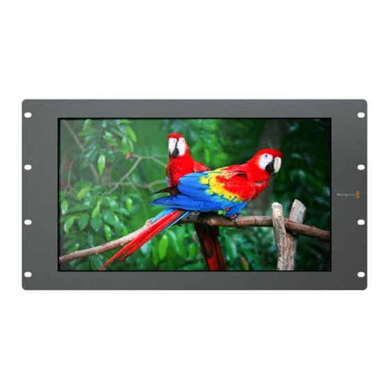
- Page 2 Video monitoring is needed everywhere in a facility. SmartView Duo provides two completely independent and beautiful 8 inch LCD screens in a 3RU rack housing less than an inch thick. SmartView HD provides an amazing 17" LCD screen in a 6RU rack housing less than an inch thick. All SmartView monitors support SD,...
-
Page 3: Table Of Contents
SmartView HD Connection Diagram Connecting SmartView to a Network Direct Ethernet Connection Ethernet Network Switch Installing the Blackmagic SmartView Utility Software Updating the Firmware in Your SmartView Configuring Blackmagic SmartView Utility Software Network Settings Pane: Device Name Network Settings Pane: Configure Address... -
Page 4: Planning Your Smartview Installation
Network configuration is performed using a direct USB 2.0 connection to a computer. You will need to provide a standard USB 2.0 type A-B male cable to connect SmartView to your computer. A laptop computer with a USB 2.0 port would be ideal for this task. - Page 5 If SmartView is to be installed high up in an equipment rack, you may wish to physically invert the LCDs for the optimum viewing angle. The images on the LCDs will automatically flip to the correct orientation when they sense an inversion.
-
Page 6: Smartview Duo Product Diagram
Getting Started SmartView Duo Monitor 1 Monitor 2 Monitor 2 Tally Ethernet Monitor 1 SD/HD-SDI with loop SD/HD-SDI In & Out through In & Out +12V main power supply connection... - Page 7 Getting Started SmartView HD Tally Ethernet SD/HD-SDI with loop In & Out through +12V main power supply connection...
-
Page 8: Optimizing The Viewing Angle
Optimizing the Viewing Angle Before you install SmartView high up in a rack, it is a good idea to check the optimum viewing angle by connecting an SDI video signal and then temporarily inverting the unit. The unit will automatically sense the inversion and flip the video images to the correct orientation. - Page 9 Step 5. Reinstate the screws in the SmartView chassis. SmartView is now ready to be installed in a high position in a rack. Once bolted into a rack, SmartView will continue to display the optimum viewing angle, even if bumped, as there are no external knobs or...
-
Page 10: Plugging In Sdi Monitoring
The illustration on the following page shows the dual-link HD-SDI outputs of a Sony HDCAM SR deck converted to a 3 Gb/s SDI signal, by HDLink Pro, and then connected to an SDI IN port on SmartView Duo. Connecting an SDI or HD-SDI source to SmartView HD As with SmartView Duo, you can connect a YUV 4:2:2 or RGB 4:4:4 signal to the SDI input of SmartView HD and SmartView HD will accept standard definition, high definition or even 2K video via SDI. -
Page 11: Smartview Duo Connection Diagram
Getting Started SmartView Duo Connection Diagram HyperDeck Shuttle disk recorder This illustration shows two examples of different SDI hardware connected to SmartView Duo simultaneously. +12V POWER HDMI IN HDMI OUT SDI IN SDI OUT The HyperDeck Shuttle disk recorder is providing a YUV 4:2:2 signal at the same time that the HDCAM SR deck is providing an RGB 4:4:4 signal. -
Page 12: Smartview Hd Connection Diagram
Getting Started SmartView HD Connection Diagram This illustration shows the multi-view SDI output of an ATEM switcher connecting to the SDI input of the SmartView HD. SmartView HD Note: All SDI and HDMI video AES/EBU IN connections are SD/HD switchable. -
Page 13: Connecting Smartview To A Network
Ethernet port on your computer. This is also a fast way to connect SmartView units via Ethernet as you don't need to run any cables back to a network switch. -
Page 14: Direct Ethernet Connection
Getting Started Direct Ethernet Connection You can connect the Ethernet port of a computer directly to a SmartView without needing a network switch. Additional SmartView units can be daisy-chained to each other so you don't have to run multiple cables... -
Page 15: Ethernet Network Switch
If you want to connect several SmartView units to your studio's existing network, you only need to connect one SmartView to the network switch. The rest can be daisy-chained to each other so you don't have to run multiple cables back to a network switch. Power must be supplied to all units. -
Page 16: Installing The Blackmagic Smartview Utility Software
Blackmagic SmartView Utility software. The Blackmagic SmartView Utility software runs on the latest Snow Leopard and Lion versions of Mac OS X. On the Windows platform, SmartView Utility software runs on both 32 and 64-bit versions of Windows 7 with the latest service packs installed. -
Page 17: Updating The Firmware In Your Smartview
Getting Started Updating the Firmware in Your SmartView Once the software installation has been completed and SmartView is powered on, it is a good idea to check that the firmware in the SmartView is up to date. Step 1. Launch the Blackmagic SmartView Utility. -
Page 18: Configuring Blackmagic Smartview Utility Software
Any discovered units will be listed in the SmartView Monitors pane with an Ethernet network icon next to their name. Select the name of the desired SmartView and you will be able to change the device name and also the monitor settings for each monitor on each SmartView. Network settings will remain grayed out and can only be changed via USB. -
Page 19: Network Settings Pane: Device Name
USB-attached unit. Network Settings Pane: Device Name It is a good idea to change the default "device name" of SmartView so each unit is easy to identify on a network, e.g. "Field Cameras 1&2", "Multi-View Output", "2K feeds", etc. -
Page 20: Monitor Settings Pane: Brightness, Contrast, Saturation
SmartView HD monitor. Leave this option disabled when viewing traditional 4:3 aspect ratio standard definition video otherwise the video will appear to be stretched. You can use Blackmagic SmartView Utility to enable or disable the "Always display SD in 16:9" setting when connected to SmartView HD hardware via Ethernet or USB. -
Page 21: Monitor Settings Pane: Identify Monitor
SmartView Monitors list. If the Blackmagic SmartView Utility does not find a SmartView at the specified address, it will not add the unit to the list and will instead present a warning, "A SmartView Monitor could not be found."... -
Page 22: Copy/Paste Display Settings
Getting Started Copy/Paste Display Settings If you have already set up one SmartView unit with monitor settings that you would like to apply to other SmartView units, you can copy and paste the settings to those other units. To do so: • select the already configured unit from the SmartView Monitors pane... -
Page 23: Tally Port Pin Connections
Getting Started Tally Port Pin Connections It is not necessary to connect the tally port of SmartView and you can skip this section if you do not intend to use the tally feature. Each SmartView Duo screen features independent tally borders in red, green or blue which can be used to indicate the status of a video signal such as on-air, preview or recording. - Page 24 Help There Are Four Steps To Getting Help. Step 1. Check out the Blackmagic Design web site www.blackmagic-design.com and click on the “Support” page for the latest support information. Step 2. Call your dealer. Your dealer will have the latest technical updates from Blackmagic Design and should be able to give you immediate assistance.
-
Page 25: Developer Information
The Blackmagic SmartView Ethernet Protocol is a text-based status and control protocol. Downloading the Free SmartView Ethernet Protocol The Blackmagic SmartView Ethernet Protocol is free. It is included in the SmartView manual and can be downloaded from http://www.blackmagic-design.com/support/ Joining the Blackmagic Design Developer List The Blackmagic Developer mailing list is designed for technical questions regarding technologies used by Blackmagic Design, eg QuickTime, Core Media, DirectShow, codecs, APIs, SDKs, etc. -
Page 26: Blackmagic 2K Format
Developer Information Blackmagic 2K Format – Overview Frame Structure ‚ Transmitted at 23.98, 24 or 25 frames per second as a Progressive Segmented Frame. The latest Blackmagic Design products use the new ‚ Active video is 2048 pixels wide by 1556 lines deep. 3 Gb/s SDI video, which allows twice the data rate of ‚... - Page 27 Developer Information Blackmagic 2K Format – Vertical Timing Reference FIELD 1 ACTIVE LINE # 1650 … … … FIELD 2 ACTIVE LINE # … … 1617 1618 … 1650...
- Page 28 Developer Information Blackmagic 2K Format – Data Stream Format DATA ANC/AUDIO STREAM DATA DATA ANC/AUDIO STREAM DATA DATA STREAM DATA STREAM WORD# 23.98/24 WORD# 25 PsF...
-
Page 29: Smartview Hd Product Diagram 7 Blackmagic Smartview Ethernet Protocol V1.1
The Blackmagic SmartView Ethernet Protocol is a text-based status and control protocol, very similar in structure to the Videohub protocol, that is accessed by connecting to TCP port 9992 on a SmartView device. Upon connection, the SmartView device sends a complete dump of the state of the device. After the initial dump, state changes are sent asynchronously. - Page 30 Monitor Settings Finally there is a configuration block for each monitor, i.e. for each LCD panel. The monitor header indicates the number of the monitor e.g. A or B for SmartView Duo, and always A for SmartView HD. MONITOR A:↵...
- Page 31 Developer Information Changing Networking Settings The network can be configured to use either DHCP or a static configuration. To enable DHCP: NETWORK:↵ Dynamic IP: true↵ ↵ To set a fixed IP address, supply all static parameters, thus: NETWORK:↵ Dynamic IP: false↵ Static address: 192.168.2.2↵...
- Page 32 Developer Information Identification and Tally Settings The Identify flag is transient, and will cause a white border to be displayed around the entire picture for a duration of 15 seconds, after which it will be reset. This feature is primarily aimed at identifying which monitor is currently being configured when it is mounted in a rack comprising multiple units.
- Page 33 Warranty 12 Month Limited Warranty Blackmagic Design warrants that this product will be free from defects in materials and workmanship for a period of 12 months from the date of purchase. If a product proves to be defective during this warranty period, Blackmagic Design, at its option, either will repair the defective product without charge for parts and labor, or will provide a replacement in exchange for the defective product.
Need help?
Do you have a question about the SmartView and is the answer not in the manual?
Questions and answers