Table of Contents
Advertisement
Quick Links
Solutions for Demanding Applications
VarTech Systems Inc.
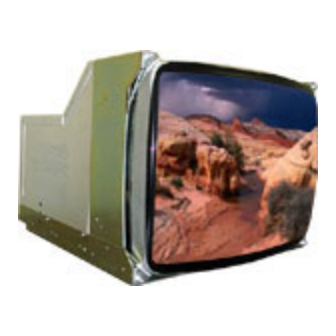
Industrial CRT and Flat Panel Displays
VT20A
20" Auto Sync Color Monitor 15 to 50kHz
For Models:
VT20A-C · VT20A-CH · VT20A-CY
VT20A-R · VT20A-RH · VT20A-M
User's Guide
Read these instructions completely before attempting to operate your new Color Display.
20" Slow Scan User Guide
150-082
Advertisement
Table of Contents

Subscribe to Our Youtube Channel
Related Manuals for VarTech Systems VT20A


Summary of Contents for VarTech Systems VT20A
- Page 1 Industrial CRT and Flat Panel Displays VT20A 20” Auto Sync Color Monitor 15 to 50kHz For Models: VT20A-C · VT20A-CH · VT20A-CY VT20A-R · VT20A-RH · VT20A-M User’s Guide Read these instructions completely before attempting to operate your new Color Display.
-
Page 2: Table Of Contents
Warning and Caution FCC Statement Connections Video Connectors Timing Controls User Controls Screen Control Definitions Power Management Troubleshooting Mechanical Drawings 10-17 VT20A-C Mechanical 11-12 VT20A-CH Mechanical VT20A-CY Mechanical VT20A-R Mechanical VT20A-RH Mechanical VT20A-M Mechanical 16-17 Specifications 20” Slow Scan User Guide 150-082... -
Page 3: Fcc Statement
Section WARNINGS and FCC Statement WARNINGS and FCC Statement WARNING TO PREVENT FIRE OR SHOCK HAZARD, DO NOT EXPOSE THIS MONITOR TO RAIN OR MOISTURE. “HIGH VOLTAGE EXISTS ON THE CATHODE-RAY TUBE ANODE LEAD OF THIS MONITOR. BEFORE SERVICING, DETERMINE THE PRESENCE OF HIGH VOLTAGE BY CONNECTING THE H.V. - Page 4 IMPORTANT SAFETY INSTRUCTIONS Prior to using this product, please ensure that you have carefully followed all the procedures outlined in the user’s manual for this product. 1. Read all of these instructions. 2. Save these instructions for later use. 3. Follow all warnings and instructions marked on the product. 4.
- Page 5 Federal Communications Commission Requirements The equipment has been tested and found to comply with the limits for a Class A digital device, pursuant to part 15 of FCC rules. These limits are designed to provide reasonable protection against harmful interference in an industrial installation. This equipment generates, uses and can radiate radio frequency energy and, if not installed and used in strict accordance with the instructions, may cause harmful interference to radio communications.
-
Page 6: Connections
Red Return Horizontal sync Green Return Vertical sync 9 Pin D CONNECTOR: CGA Function EGA Function Ground Ground Red Intensity CGA/EGA TTL INPUT Standard for VT20A-CH and VT20A-RH Green Green Blue Blue Intensity Green Intensity Blue Intensity Horizontal Sync Horizontal Sync... -
Page 7: Timing
Timings VGA1 640 X 350 VGA2 720 X 400 VGA3 640 X 480 MAC35k Mode Hor. Freq (kHz) 31.468 31.468 31.468 34.975 Vert. Freq. (Hz) 70.09 70.09 59.94 66.62 Dot Clock (MHz) 25.175 28.322 25.175 31.3344 Hor. Total Time 31.778 31.778 31.778 28.59... -
Page 8: Controls
Section CONTROLS CONTROLS CONTROL LOCATION NOTE: VT20A-C, VT20A-CH, VT20A-R, All controls are located on the right side of the monitor. VT20B-R, VT20A-RH, VT20A-M All controls are located on the front of the monitor. VarTech OSD (On Screen Display menu) CONTROLS AND ADJUSTMENTS:... -
Page 9: Screen Control Definitions
SCREEN CONTROL DEFINITIONS Feature Function To adjust the overall screen intensity Brightness To adjust the intensity difference between the video image and the background Contrast display raster To adjust the vertical position of the display image V-center To adjust the vertical size of the display image V-size To adjust the horizontal position of the display image H-phase... -
Page 10: Power Management
Section POWER MANAGEMENT POWER MANAGEMENT POWER MANAGEMENT FUNCTION The Power Management function, which is controllable through the required software, provides four distinct power states: DISPLAY POWER MANAGEMENT SIGNALING (DPMS) Mode Function Normal operation; screen stays on. Power LED is green. Standby Screen blanks after preset idle time. -
Page 11: Troubleshooting
In the event that you experience trouble with your Display, check the following items before contacting Vartech Systems. The most common problems usually involve an incorrectly configured Video Card or an incorrect connection from the Video Card to the Display. Do not exceed the maximum refresh rate recommended for the display. -
Page 12: Mechanical Drawings
Section MOUNTING INSTRUCTIONS MOUNTING INSTRUCTIONS Mechanical Drawings Model Description Page(s) VT20A-C 20” Chassis Mount Mechanical Drawing 11-12 VT20A-CH 20” Honeywell Configured Chassis Mount Mechanical Drawing VT20A-CY 20” Yokogawa Configured Chassis Mount Mechanical Drawing VT20A-R 20” Rack Mount Mechanical Drawing VT20A-RH 20”... -
Page 13: Specifications
15kHz to 50kHz Vertical Frequency 45Hz to100Hz Bandwidth 90MHz Video Input Connector HD15(F) and 5BNC DB9 (VT20A-CH and VT20A-RH) Video Input Signal Analog 0.7 Vp-p Sync Separate Horizontal and Vertical TTL Syncs Or Composite TTL Syncs Or Sync on Green 0.3V p-p Temperature Operating: 0 to 50ºC... - Page 14 VARTECH SYSTEMS INC. HEADQUARTERS 11529 Sun Belt Ct. Baton Rouge, Louisiana 70809 Toll-Free: 800.223.8050 International Phone: 001.225.298.0300 Fax: 225.297.2440 E-mail: sales@vartechsystems.com 150-082-004 4.27.04 www.vartechsystems.com 20” Slow Scan User Guide 150-082...
Need help?
Do you have a question about the VT20A and is the answer not in the manual?
Questions and answers