Advertisement
Table of Contents
- 1 Instructions for Use
- 2 Installation and Servicing
- 3 Guarantee Registration
- 4 Table of Contents
- 5 Important Information
- 6 General Data
- 7 Water Systems
- 8 Flue & Ventilation
- 9 Installation
- 10 Electrical Wiring
- 11 Commissioning
- 12 Instructions to the User
- 13 Servicing
- 14 Fault Finding
- 15 Replacement of Parts
- 16 Spare Parts
- Download this manual
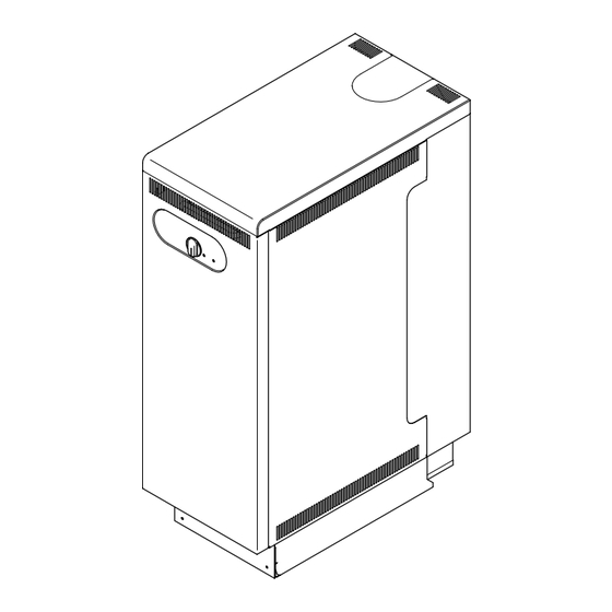
Installation and Servicing
Hideaway 40C FF
G.C. No. 41-047-38
Hideaway 50C FF
G.C. No. 41-047-39
Hideaway 60C FF
G.C. No. 41-047-40
Chimney
Fanned Flue Boiler
This is a Cat I
Reference in these instructions to British Standards and Statutory
Regulations/Requirements apply only to the United Kingdom.
For Ireland the rules in force must be used.
The instructions consist of three parts, User, Installation and Servicing Instructions, which includes the Guarantee Registration
Card. The instructions are an integral part of the appliance and must, to comply with the current issue of the Gas Safety
(Installation and Use) Regulations, be handed to the user on completion of the installation.
Thank you for installing a new Glow-worm appliance in your home.
Glow-worm appliances' are manufactured to the very highest standard so we are pleased
In the centre pages are to be found your Guarantee Registration Card, which we recommend you complete and
If this card is missing you can obtain a copy or record your registration by telephoning the Heatcall Customer
Our Guarantee gives you peace of mind plus valuable protection against breakdown by covering the cost of:
❏
✔
All replacement parts
❏
✔
All labour charges
❏
✔
All call-out charges
One Contact Local Service
Instructions for Use
To b e l e f t w i t h t h e u s e r
Appliance
2H
Guarantee Registration
to offer our customers' a Comprehensive First Year Guarantee.
return as soon as possible.
Service number 01773 828100.
REGISTER YOUR GLOW-WORM APPLIANCE
FOR 1ST YEAR GUARANTEE PROTECTION
CALL 0208 247 9857
Customer Services:
Tel: (01773) 828100
Fax: (01773) 828070
Hepworth Heating Ltd.,
Nottingham Road, Belper, Derbyshire. DE56 1JT
General/Sales enquiries:
Tel: (01773) 824141 Fax: (01773) 820569
2000225005B.03.02
Advertisement
Table of Contents

Related Manuals for Glow-worm Hideaway 40C FF


Summary of Contents for Glow-worm Hideaway 40C FF
-
Page 1: Instructions For Use
Guarantee Registration Thank you for installing a new Glow-worm appliance in your home. Glow-worm appliances' are manufactured to the very highest standard so we are pleased to offer our customers' a Comprehensive First Year Guarantee. In the centre pages are to be found your Guarantee Registration Card, which we recommend you complete and return as soon as possible. -
Page 2: Table Of Contents
Important Information TESTING AND CERTIFICATION This boiler is tested and certificated for safety and performance. It is therefore important that no alteration is made to the boiler, without permission, in writing, from Hepworth Heating Ltd. Any alteration not approved by Hepworth Heating Ltd., could invalidate the certification, boiler warranty and may also infringe the current issue of the Statutory Requirements, see Section 1.3. - Page 3 The frequency of servicing will depend upon The Glow-worm Hideaway C FF series are fanned flue boilers the particular installation conditions and usage, but in general with a chimney flue adapter.
- Page 4 Instructions for Use To Turn the Appliance On Turn the electrical supply on to the boiler and check that all BOILER remote controls are calling for heat. TEMPERATURE Turn the boiler temperature control clockwise to any position CONTROL between “0” and "Max", see diagram 1. "Max"...
-
Page 5: General Data
1 General Data NOTE: The boiler casing can be set at two heights, MAX.or MIN. WATER CONNECTIONS Rc1 reduced with DISTRIBUTOR TUBE to in. B.S.P.T.) (pumped return) WATER CONNECTIONS Rc1 (1in. B.S.P.T.) GAS CONNECTION in. B.S.P.T.) INSIDE DIAMETER OF ADAPTOR FOR 100mm (4in.) NOMINAL DIAMETER FLUE TO BS567 GENERAL DIMENSIONS - given in millimetres... - Page 6 1 General Data 1.3 Statutory Requirements The installation of this appliance must be carried out by a competent person and must be in accordance with the relevant requirements of the current issue of: Manufacturer’s instructions supplied. The Gas Safety (Installation and Use) Regulations, Building Regulations, Local Water Company Bye-laws, The Building Standards (Scotland) Regulations, (applicable in Scotland), Health and Safety at Work Act, Control of Substances Hazardous...
- Page 7 1 General Data 1.8 Boiler Location This boiler is not suitable for outside installation. The boiler casing can be fitted at two heights. Refer to WORKTOP 320 MIN. diagram 1.5. The boiler is assembled at the factory with the control box and heat shield fitted in the lower position.
-
Page 8: Water Systems
2 Water Systems 2.1 Water Pressure Head REFER TO BS 5546 The boiler shall only be connected to a cistern water supply with 22mm VENT a minimum head of 1metre (3ft3in) and a maximum head of 27metres (90ft) which has an open vent in the system. 15mm COLD FEED The working pressure must be within the range 0.1bar to 2.7bar INDIRECT... -
Page 9: Flue & Ventilation
3 Flue and Ventilation Important Notes The flue must be installed in accordance with the rules in force SEALING AND in the countries of destination. CLAMPING The flue must be in accordance with the current issue of PLATE BS5440 Part 1. The Chimney Flue Adapter Kit (Pt. - Page 10 3 Flue and Ventilation 3.4 Timber Frame Buildings AIR VENT TABLE - FOR ROOM/ SPACE INSTALLATIONS If the boiler is to be installed in a timber frame building it should be fitted in accordance with the Institute of Gas Engineers EFFECTIVE AREA OF VENT document IGE/UP/7/1998.
-
Page 11: Installation
4 Installation General Installation Notes ALTERNATIVE The appliance pack contains :- HEATING OR DOMESTIC Boiler. HOT WATER Casing panels, packed seperately. FLOW Loose items fittings pack, see list in pack. The chimney flue adapter with flue extension is supplied ALTERNATIVE seperately. - Page 12 4 Installation 4.4 Pipework When the front tappings are used, it is essential that any pipework or fittings do not project more than shown in diagram 4.4. When using a rear tapping with Rc (1in BSP) fitting for 28mm od UPPER CASING pipework, it is recommended that a short nipple and an Rc BRACKET...
- Page 13 4 Installation 4.6 Side Casings SIDE Fit the side casings by locating their lugs into the appropriate CASING SPRING slot in the boiler plinth, see diagram 4.7, depending on the (R.H.SHOWN) CLIP required height, there are two options, see section 1.7. Secure the casing sides to the front and rear upper casing brackets with self-tapping screws supplied, see diagrams 4.7 and 4.8.
- Page 14 4 Installation 4.8 Flue / Boiler Connection Remove the three self-tapping screws from the lower part of the control box support bracket, see diagram 4.10. Undo the wing nut that secures the top of the heat shield and ACCESS carefully hinge down control box and heat shield, see diagram DOOR 4.10.
- Page 15 4 Installation 4.9 Water & Gas connections Replace fan access door, heat shield and control box. Note: When replacing the fan access door make sure the lip at the top of door fits into and behind the slotted bracket located at the top of the boiler.
-
Page 16: Electrical Wiring
5 Electrical Wiring SECURING CONTROL SCREWS COVER TERMINAL BLOCK CONTROL BOILER TEMPERATURE CONTROL TERMINAL BLOCK CONNECTIONS Diagram 5.1 HEAT RESISTANT CABLE 5.1 Control Box Access Remove control box cover by undoing the four securing screws (two on control box, two on the heat shield) and lift off, see diagram 5.1. -
Page 17: Commissioning
6 Commissioning Turn the boiler temperature control clockwise to “Max”. IMPORTANT NOTE The ignition system will operate to light the boiler. After a pre- The WARNING NOTICE attached to the front casing must only be removed by the user. set time if ignition has not taken place the boiler will shutdown. To re-start the lighting sequence, turn the boiler temperature Please ensure the “Benchmark”... - Page 18 10 minutes after the burner has lit, making sure that all other gas burning appliances and pilot lights are off. The gas rates: Hideaway 40C FF : 1.7m /h (49ft BOTTOM PLINTH Hideaway 50C FF : 2.1m...
-
Page 19: Instructions To The User
7 Instructions to the User Instruct and demonstrate the safe and efficient operation of the boiler, heating system and domestic hot water system. Advise the user, that to ensure the continued efficient and safe operation of the boiler, it is recommended that it is checked and serviced at regular intervals. - Page 20 8 Servicing 8.1 Access SECURING SCREWS Remove the boiler front casing panel, refer to section 6.8. Remove the bottom plinth panel by unscrewing the two dog point screws securing the panel to the boiler plinth, see diagram 8.4. Disconnect gas valve from gas cock and unplug electrical plug from gas valve, firstly removing electrical plug securing screw, see diagram 8.2.
- Page 21 8 Servicing 8.2 Boiler Flueways WING NUT Remove flueway baffles noting that there are 1 centre and 2 side flueway baffles, see diagram 8.8. Place a sheet of paper in the combustion chamber to catch any flue debris. Thoroughly clean boiler flueways and fins with a suitable stiff brush.
- Page 22 8 Servicing 8.4 Service Checks Inspect the spark electrode and clean and replace as necessary, see diagram 8.12. Check the condition of the side and rear insulation panels in the combustion chamber. Check the condition of the seals on the boiler access door and the combustion chamber cover.
-
Page 23: Fault Finding
9 Fault Finding IMPORTANT. On completion of the Fault Finding task which has required the breaking and remaking of the electrical BOILER connections, the continuity, polarity, short circuit and resistance TEMPERATURE to earth checks must be repeated using a suitable multimeter. CONTROL WARNING. - Page 24 9 Fault Finding 9.2 Electrical Supply Failure Failure of the electrical supply will cause the burner to go out. Operation will normally resume on the restoration of the electrical supply. If the burner does not relight after an electrical supply failure and the reset neon on the control panel is lit, turn the burner temperature control to “0”, wait 30 seconds, then fully clockwise to “Max.”...
- Page 25 9 Fault Finding NEON KEY (see P.C.B) PRESSURE SWITCH NEON 1 = = MAINS ON NEON 2 = = DEMAND ON NEON 3 = = FAN RUNNING NEON 4 = = BURNER LIT = SAFETY NEON 5 = TEMPERATURE LIMITER NEON 6 = = FLAME FAILURE CONTROL...
-
Page 26: Replacement Of Parts
10 Replacement of Parts IMPORTANT NOTES Carefully pull the boiler temperature control knob away from the P.C.B. REMEMBER, When replacing a part on this appliance, use only Disconnect the electrical plugs from the control board (PCB) spare parts that you can be assured conform to the safety and slightly bending back the retaining latches to allow withdrawal, performance specification that we require. - Page 27 10 Replacement of Parts 10.3 Electrode When re-assembling, make sure that the air pressure tubes are fitted as before and that the fan duct engages fully into the flue Remove front panel to gain access, see section 6.8. duct extension piece. Refer to the relevant paragraphs of the servicing section to The polarity of the electrical connections is not important.
-
Page 28: Spare Parts
11 Spare Parts 11.1 Part Identification 11.2 Ordering The key number in diagram 11.1 and the first column of the list When ordering any spare part please quote the part number will help identify the spare part. and the description from the list together with the model name and serial number information from the data label.
Need help?
Do you have a question about the Hideaway 40C FF and is the answer not in the manual?
Questions and answers