Advertisement
Quick Links
Installation & Servicing Instructions
40
GC No. 41 319 20
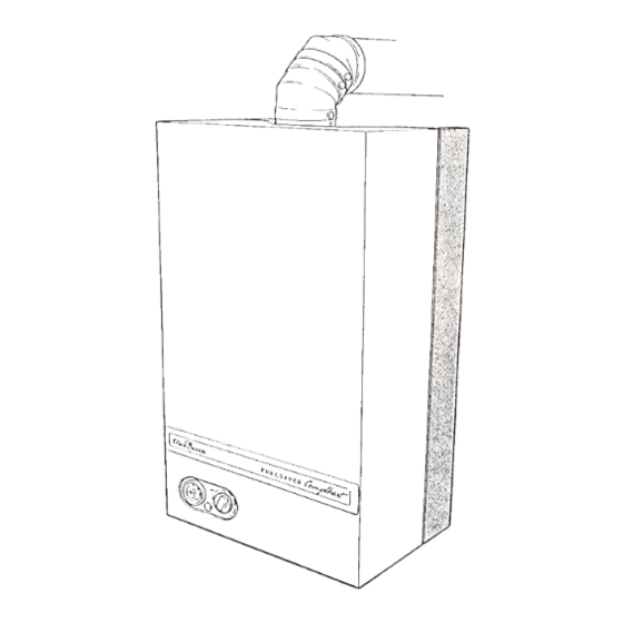
Fanned Flue Sealed System Boiler
Reference in these instructions to British Standards and Statutory
Regulations/Requirements apply only to the United Kingdom.
For Ireland the rules in force must be used.
One Contact Total Service
Supplied By www.heating spares.co Tel. 0161 620 6677
To b e l e f t w i t h t h e u s e r
T h i s i s a C a t I
Customer Services:
Tel: (01773) 828100
Fax: (01773) 828070
55
GC No. 41 319 19
BS 6332
a p p l i a n c e
BS 5258
2 H
Hepworth Heating Ltd.,
Nottingham Road, Belper, Derbyshire. DE56 1JT
General/Sales enquiries:
Tel: (01773) 824141 Fax: (01773) 820569
220677A.05.95
COSHH
Advertisement

Related Manuals for Glow-worm 40 GC 41 319 20


Summary of Contents for Glow-worm 40 GC 41 319 20
- Page 1 220677A.05.95 COSHH Installation & Servicing Instructions To b e l e f t w i t h t h e u s e r GC No. 41 319 20 GC No. 41 319 19 Fanned Flue Sealed System Boiler BS 6332 T h i s i s a C a t I a p p l i a n c e BS 5258...
- Page 2 1 General All dimensions in millimetres SAFETY VALVE KEY: DISCHARGE 22mm COMPRESSION CENTRAL HEATING in. BSPT) GAS CONNECTION STD FLUE TERMINAL = 63 LONG FLUE TERMINAL = 61 Diagram 1.1 OVERALL DIMENSIONS The instructions consist of two parts, Installation and competent person in accordance with the relevant Servicing and Instructions for Use.
- Page 3 1 General CE Mark DATA TABLE 1 The CE mark on this appliance shows compliance with MODEL Directive 90/396/EEC on the approximation of the Laws of the Member States relating to appliances burning 33.3kg 33.3kg LIFTING gaseous fuels. (73.4lb) (73.4lb) WEIGHT The CE mark on this appliance shows compliance with Directive 73/23/EEC on the harmonization of the Laws...
-
Page 4: Water System
2 Water System 2.1 General Notes WATER FLOW RATE AT 11 C (20 F) DIFFERENTIAL The installation of the boiler must comply with the requirements of the current issue of BS6798. UNIT litre/min. 15.3 21.0 2.2 Safety Valve gal/min. The safety valve, preset at 3bar, is an integral part of the boiler and cannot be adjusted. -
Page 5: Water Systems
2 Water Systems 2.8 Water Make Up 2.14 Domestic Hot Water Cylinder Provision should be made for replacing water lost from SINGLE FEED INDIRECT CYLINDERS ARE NOT the system using a make up bottle mounted in a position SUITABLE AND SHOULD NOT BE USED. higher than the top point of the system, connected The domestic hot water cylinder must be of the indirect through a non-return valve to the return side of the... -
Page 6: Boiler Location
3 Boiler Location 3.1 General A compartment used to enclose the boiler must be designed and constructed specifically for this purpose. The boiler may be installed in any room although An existing cupboard or compartment modified for the particular attention is drawn to the requirements of the purpose may be used, refer to the current issue of current issue of BS7671 with respect to the installation BS6798 for guidance. - Page 7 4 Flue The flue must be installed in accordance with the current STANDARD FLUE TERMINAL ILLUSTRATED issue of BS5440 Part 1. The air and flue ducting connect to the top of the boiler using an elbow which can be positioned to the left or right hand side or the rear.
- Page 8 4 Flue 4.1 Terminal Position The minimum acceptable siting dimensions for the terminal from obstructions, other terminals and ventilation openings are shown in diagram 4.3. The terminal must be exposed to the external air, the position allowing free passage of air across it at all times.
- Page 9 5 Preparation 5.1 Unpacking Remove the top carton from the boiler. To remove the outer case, slide the information plate up to access and remove the single securing screw, see diagram 5.1, unhook the case at the top and lift it off. Remove the cover of the inner case, secured with four screws, see diagram 5.2.
- Page 10 5 Preparation Remove the two boiler securing screws, see diagram 5.4 BOILER then separate the boiler from the mounting frame, by SECURING SCREW (2) pulling the location studs/clips apart then unhook it at the top. BOILER LOCATION MOUNTING FRAME STUD(S) and CLIP(S) BOILER MOUNTING FRAME Diagram 5.4...
- Page 11 6 Installing the Flue Make sure that the isolation valves are at the bottom facing forward and that the frame top is horizontal, then WALL mark the four fixing points through the holes in the two SLEEVE horizontal straps, do not drill the holes, see diagram 6.4. Position the flue template on the wall, the arrow points on the centres of the two upper fixing points previously marked, see diagram 6.1 which also gives dimensions.
- Page 12 6 Installing the Flue 6.6 Flue Preparation STANDARD FLUE TERMINAL ILLUSTRATED Rear Flue FLUE Mark and cut the air duct terminal assembly, see diagram DUCT 6.5 and the flue duct, see diagram 6.6 to the lengths required, cutting square and removing any burrs. Refer to diagram 6.9, mark through the holes in the flue 'R' + 107 elbow assembly and drill the flue duct as shown.
- Page 13 6 Installing the Flue Mark the position of the air duct terminal assembly From outside, place the air duct/terminal assembly and securing holes and drill two 3mm diameter holes through flue duct into the flue hole. Make sure that the flue the air duct/terminal assembly.
- Page 14 6 Installing the Flue Locate the flue duct into the flue elbow assembly and STD FLUE TERMINAL = 63 WALL SLEEVE secure with the screws provided. LONG FLUE TERMINAL = 61 Secure the air duct terminal to the flue elbow with the two self tapping screws supplied in the loose items pack, making sure that the flue duct is correctly located into FLUE...
- Page 15 7 Gas, Water and Electrical Connections 7.4 Electrical Connections WARNING. The boiler must be earthed. Take the electrical connector from the loose items pack and remove the two screws and cover, see diagram 7.3. Using cable at to the current issue of BS6500 Table 16 of a suitable length connect the mains supply cable to the appropriate terminals of the connector, see diagram 7.3.
- Page 16 8 Boiler and Flue Fixing 8.1 Mounting the Boiler After installing the boiler mounting frame, gas and water, making the electrical connections and preparing the flue components continue as below: Lift the boiler into position, hooking it onto the boiler mounting frame at the top, see diagram 8.1 then loosely fit the two, previously removed, boiler securing screws at the top, see diagram 5.4.
- Page 17 8 Boiler and Flue Fixing 8.2 Flue Assembly to Boiler - Connection NOTE. The fan could be fitted with transit clips, see diagram 8.6 which will need removing. Slacken but do not remove the fan securing screws and flue hood wing nuts, see diagram 8.4. Secure the flue assembly to the spigot on top of the boiler, see diagram 8.5.
- Page 18 9 Completion and Commissioning 9.1 System Commissioning Commissioning must only be carried out by a competent person in accordance with the current issue of BS6798. BLEED IMPORTANT SCREW Check that the boiler is isolated from the electrical THE CAP ON THIS AIR VENT SHOULD supply at the external isolator.
- Page 19 9 Completion and Commissioning 9.2 Initial Lighting and Testing and Adjustment The set pointer on the pressure gauge should be set to coincide with the cold fill pressure. Refit the inner case, securing it with the four screws previously removed. Make sure that the case is correctly fitted and sealed.
- Page 20 9 Commissioning and Completion 9.4 Testing - Gas 9.3 Testing - Electrical Checks to ensure electrical safety should be carried out Test for gas soundness around the boiler gas by a competent person. components, using a suitable leak detection fluid. In the event of an electrical fault after installation of the Check the main burner gas pressure at least 10 minutes after the burner has lit, refer to Data label or Appliance...
-
Page 21: Instructions To The User
9 Commissioning and Completion 9.5 Heating System TABLE 4 Check that all remote controls are calling for heat. APPROX.GAS RATE Allow the system to reach maximum working temperature and examine for water leaks. The boiler MODEL 40 should then be turned off and the system drained as 37.7 43.4 48.8... - Page 22 11 Servicing 11.1 Notes To ensure the continued efficient and safe operation of the boiler it is recommended that it is checked and serviced at regular intervals. The frequency of servicing will depend upon the particular installation conditions and usage, but in general once a year should be enough. 12 to 14 FLAME LENGTH It is the Law that any servicing must be carried out by a competent person.
- Page 23 11 Servicing 11.4 Main Burner ELECTRODE SECURING Slacken the flue hood securing angle wing nuts, see SCREW diagram 11.2. PILOT BURNER ASSEMBLY Remove the combustion chamber front panel, secured ELECTRODE SECURING with four screws and a wing nut, see diagram 11.2. SCREW (2) Disconnect the pilot pipe union connector and ignition lead, see diagram 11.3.
-
Page 24: Fault Finding
11 Servicing 11.6 Cleaning Heat Exchanger. 11.7 Pilot Injector Disconnect the two electrical connections at the fan, see If the pilot flame is not burning correctly, it may be diagram 11.2. It is not necessary to disconnect the green necessary to remove the pilot injector. and yellow earth cable. - Page 25 12 Fault Finding Neon Indicators - An Aid to Fault Finding THE NEON INDICATORS ARE AN AID TO FAULT FINDING ONLY. FAILURE OF ANY OF THE NEON INDICATORS DOES NOT WARRANT THE REPLACEMENT OF AN OTHERWISE SATISFACTORY PRINTED CIRCUIT BOARD (PCB). IF RED NEON ON FASCIA IS ILLUMINATED FILL CENTRAL HEATING SYSTEM, PRESSURE 0.7bar MIN.
- Page 26 12 Fault Finding Before detailed checking of electrical components ensure that remote controls are calling for heat. Check that the gas supply is free of obstructions and purged of air. Isolate the elctrical supply, check all cables, connections and the printed circuit board (PCB) fuse.
- Page 27 12 Fault Finding MAIN TERMINAL STRIP Is there 240V ~ between Replace thermostat yellow connection on thermostat and 2 ? Check yellow cable between Is there 240V~between N/c printed circuit board and air Is neon 3 lit ? on air pressure pressure switch.
- Page 28 12 Fault Finding MAIN TERMINAL STRIP Is there 240V ~ between Inspect air tubes for leaks (N/o) on air pressure kink and correct fitting. switch and 2 ? If satisfactory replace faulty air pressure switch. Isolate supply, test harness Is there 240V~between continuity.
- Page 29 12 Fault Finding INFORMATION MAIN TERMINAL STRIP CONNECTIONS PLATE CONTROL THERMOSTAT CONNECTIONS CONTROL BOARD CONNECTIONS LOW WATER PRESSURE SWITCH RESET BUTTON PUMP 3 POLE CONNECTOR NEON RESET BUTTON Diagram 12.4 INDICATOR SPARK ELECTRODE WATER DIFFERENTIAL PRESSURE SWITCH FUSE TYPE OVERHEAT CUT-OFF CONTROL THERMOSTAT...
- Page 30 12 Fault Finding CIRCULATION BLUE PUMP FAN ASSEMBLY L N E GREEN/ YELLOW SPARK PURPLE CHASSIS FUSE ELCTRODE EARTH TYPE F1A WATER PRINTED 1 AMP PRESSURE CIRCUIT BOARD BLUE WARNING NEON BLUE B R O W N CHASSIS BLUE EARTH BROWN AIR PRESSURE BLUE...
-
Page 31: Replacement Of Parts
13 Replacement of Parts 13 Replacement of Parts 13.9 Pilot Injector 13.1 Replacement of parts must only be carried out by a Gain access as the relevant part of Section 11.4 and competent person. proceed as Section 11.7. Before replacing any part isolate the gas and electrical When relighting check that the flame length is as shown supplies. - Page 32 13 Replacement of Parts 13.10 Control Thermostat Gain access as Section 13.2 Remove the control knob and fascia by removing the screws, see diagram 8.2. Remove the thermostat securing nut, see diagram 13.1. Remove the electrical connections from the thermostat PLASTIC body.
- Page 33 13 Replacement of Parts 13.14 Safety Valve: diagram 13.3 Release the water pressure and drain the boiler, refer to Section 13.3. Remove the pressure gauge connection as Section 13.3. Disconnect the union nut to release the discharge pipe. Place a spanner on the hexagon on the volume vessel and break the union nut connection to release and then unscrew the safety valve.
- Page 34 13 Replacement of Parts 13.17 Control Board (PCB): diagram 13.6 13.18 Multifunctional Control and Pilot Solenoid: diagram 13.7 Disconnect all multi-pin connectors. Disconnect all electrical connections at the Remove the blue and brown cables from terminals 4 and multifunctional control. 5 also disconnect the yellow cable from the control thermostat and the white cable from the overheat cutoff Remove the four securing screws from the left hand side...
- Page 35 13 Replacement of Parts 13.19 Pump: diagram 13.8 AUTOMATIC Release the water pressure and drain, refer to AIR VENT Section 13.3. Disconnect the “in-line” connections at the pump. Disconnect the pump at the union connections. HEAT EXCHANGER Discard the sealing washers and fit the new ones supplied.
- Page 36 13 Replacement of Parts 13.22 Combustion Chamber Insulation: INSULATION diagram 13.10 PANEL Remove the securing clip and insulation panel. Take care when sliding the replacement insulation into position securing it with the original clip. The rear insulation cannot be removed until the heater exchanger is removed, see Section 13.21, then slide the insulation from behind the heat exchanger.
- Page 37 13 Replacement of Parts 13.26 Air Pressure Switch: diagram 13.13 When refitting make sure that the coloured tube is fitted as shown and that the electrical connections are made as Remove the pressure tubes and electrical connections. shown in diagram 12.5. Release the air pressure switch from its bracket by The polarity of the electrical connections is important.
-
Page 38: Spare Parts
14 Spare Parts 14.1 Part Identification 14.2 Ordering The key number in diagram 14.1 and the first column of When ordering any spare part, please quote the part the list will help to identify the spare part. number and the description from the list together with the model name and serial number information from the data label. - Page 39 14 Spare Parts Diagram 14.1 220677A Supplied By www.heating spares.co Tel. 0161 620 6677...
- Page 40 Control of Substances Hazardous to Health Information for the Installer and Service Engineer. Under Section 6 of The Health and Safety at Work Act 1974, we are required to provide information on substances hazardous to health. The adhesives and sealants used in this appliance are cured and give no known hazard in this state.
Need help?
Do you have a question about the 40 GC 41 319 20 and is the answer not in the manual?
Questions and answers