
Related Manuals for Glow-worm 12 hxi G.C.No. 41-019-01


Summary of Contents for Glow-worm 12 hxi G.C.No. 41-019-01
-
Page 1: And Servicing
Installation and Servicing Condensing Boilers/Ultracom hxi 12 hxi G.C.No. 41-019-01 15 hxi G.C.No. 41-019-02 18 hxi G.C.No. 41-019-03 24 hxi G.C.No. 41-019-04 30 hxi G.C.No. 41-019-05 38 hxi G.C.No. 41-019-06... -
Page 2: Guarantee Registration
Guarantee Registration Thank you for installing a new Glow-worm appliance in your home. Glow-worm appliances are manufactured to the very highest standard so we are pleased to offer our customers a Comprehensive Guarantee. This product is guaranteed for 24 months from the date of installation or 30 months from the date of manufacture, whichever is the shorter, for parts and labour. -
Page 3: Table Of Contents
Table of ConTenTS These instructions consist of, Installation, Servicing, fault finding, Replacement of Parts and Spares. The instructions are an integral part of the appliance and must, to comply with the current issue of the Gas Safety (Installation and Use) Regulations, be handed to the user on completion of the installation. -
Page 4: Warnings
Glow- The following handling techniques and precautions should be worm. considered: Any alteration not approved by Glow-worm, could invalidate - Grip the boiler at its base the certification, boiler warranty and may also infringe the - Be physically capable current issue of the statutory requirements. -
Page 5: Statutory Requirements
Building Regulations, approved document L1 ( in the UK) and the following current issues of: 1) Central heating system specification (CheSS) 2) Controls for domestic central heating system and hot water. BRECSU. 0020107233_00 - 06/11 - Glow-worm - 5 -... -
Page 6: Boiler Design
Section 35. authorised by Glow-worm. Servicing/maintenance should be carried out by a competent If a part is required contact Glow-worm’s own service person approved at the time by the Health and Safety organisation using the telephone number on the inside front... -
Page 7: Boiler Specification
TECHNICAL DATA 1 boiler Specification SEDBUK rating % 2005 90.5 90.5 90.4 SEDBUK rating % 2009 88.7 88.7 88.6 SEDBUK rating % 2005 90.5 90.6 90.8 SEDBUK rating % 2009 88.9 88.7 89.2 0020107233_00 - 06/11 - Glow-worm - 7 -... -
Page 8: Boiler Dimensions
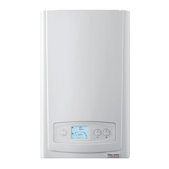
The general arrangement of the boiler is shown in diagram 2.1. and the hydraulic and gas schematic, diagram 2.2. Diagram 2.1 The data label is positioned on the front of the inner casing panel. 0020107233_00 - 06/11 - Glow-worm - 8 -... -
Page 9: Boiler Location, Clearances And Ventilation
If the boiler is to be installed in a timber frame building it should be fitted in accordance with the Institute of Gas Engineers document IGE/UP/7/1998. If in doubt seek advice from local gas undertaking or Glow-worm. 3.4 Combustible Material Diagram 3.1... -
Page 10: Evacuation Of Combustion Gas
4.1 Regulation homeowner to check the flue outlet and clear visible insects from the terminal end. Only flue accessories supplied by Glow-worm H* and J* See diagram 4.2. These dimensions comply with must be used. the building regulations, but they may need to be increased to Different flue outlet configurations can be carried out. - Page 11 (2) These dimensions comply with the building regulations, from surface or a boundary facing the terminal but they may need to be increased to avoid wall staining and nuisance from pluming depending on site conditions. 0020107233_00 - 06/11 - Glow-worm - 11 -...
- Page 12 Each time an additional 90° bend is necessary (or 2 at 45°), the length (L) must be reduced by 1 m. 1 Gasket (fitted) Type Max length Ø 60/100 10 m Ø 80/125 25 m 0020107233_00 - 06/11 - Glow-worm - 12 -...
- Page 13 7.10 8.75 11.30 13.25 18.30 Load (80C°/60°C) exhaust temperature (ºC) At Min Thermal 56.0 56.0 56.0 44.0 44.0 46.0 Load (40C°/30°C) At Max Thermal 69.0 70.0 69.0 66.0 57.0 73.0 Load (80C°/60°C) 0020107233_00 - 06/11 - Glow-worm - 13 -...
- Page 14 INSTALLATION Diagram 5.1 0020107233_00 - 06/11 - Glow-worm - 14 -...
-
Page 15: Water Systems
Health and Safety Executive, as defined in the for Ie: The current edition of I.S.813 “Domestic Gas approved document G3. Installations”. for Ie: The current edition of I.S.813 “Domestic Gas Installations”. 0020107233_00 - 06/11 - Glow-worm - 15 -... - Page 16 A pressure gauge with a set pointer and covering at least 0 to 4 bar (0 to 60 lb/in2) shall be fitted permanently to the system in a position where it can be seen when filling the system. 0020107233_00 - 06/11 - Glow-worm - 16 -...
- Page 17 CONNECTION VALVE UNION HEATING CIRCUIT AIR GAP DRAIN POINT DRAIN TUNDISH Method 1 POINT Method 2 Diagram 5.4 BOILER TYPE CA BACKFLOW FLOW RETURN PREVENTION DEVICE CONTROL CONTROL 0020107233_00 - 06/11 - Glow-worm VALVE VALVE SUPPLY - 17 - PIPE...
-
Page 18: Installation Preparation
If flue extension pipes are to be used then a core drill size of 125mm is required. This will allow the extension pieces to slope at 44mm/metre (2.5°) towards the boiler. Diagram 6.2 0020107233_00 - 06/11 - Glow-worm - 18 -... -
Page 19: Boiler Fixing
Lower the boiler slowly and engage onto the hanging bracket, see diagram 7.2. Remove the polystyrene base support. Diagram 7.1 Diagram 7.2 0020107233_00 - 06/11 - Glow-worm - 19 -... -
Page 20: Gas/Water & Condensate Connection
8.3. It is recommended that any external condensate drain pipe is protected and also preferably of 32mm diameter, to prevent 0020107233_00 - 06/11 - Glow-worm - 20 -... - Page 21 INSTALLATION Diagram 8.3 0020107233_00 - 06/11 - Glow-worm - 21 -...
-
Page 22: Electrical Connection
Slacken the cable strain relief and route the pump electrical supply cable and connect as shown in diagrams 9.1 and 9.2. 9.3 System Controls If you are fitting the Glow-worm Options Board Kit, please refer to the instructions supplied with the kit for the system wiring. -
Page 23: Commissioning
Sealed system only - fill the system to a pressure of 1.0bar. 2. Vent all air from the system - repeat as necessary until the system is full and all the air has been vented. 0020107233_00 - 06/11 - Glow-worm - 23 -... - Page 24 0.53 18.7 0.39 1.29 45.6 0.95 12hxi noTe: If you have fitted a Glow-worm Options Board Kit, please refer to the instructions supplied with the kit for 15hxi 0.53 18.7 1.61 0.39 1.19 completion of commissioning. Do not operate the boiler without water.
-
Page 25: Instruct The User
● It is the Law that any servicing is carried out by a ● Leave these instructions and the ‘Benchmark’ Installation, competent person approved at the time by the Health and Commissioning and Service Record with the user. Safety Executive. 0020107233_00 - 06/11 - Glow-worm - 25 -... - Page 26 As an option, a chargeable boiler performance and function and immediately press and hold in the “+” button. After service can be provided by Glow-worm Service by calling approximately 5 seconds “Hi” will be displayed. Pressing telephone No. 01773 828100.
-
Page 27: Servicing 11
● Remove the front casing panel, see diagram 11.2 and hinge down the control box. Taking care not to touch any internal components, proceed as follows: ● Connect the CO2 combustion analyser to the relevant test point, see diagram 11.1. 0020107233_00 - 06/11 - Glow-worm - 27 -... -
Page 28: Gas Rate Check
CO/CO2 ratio is acceptable. Advice can circuit seals have been verified and the inlet gas pressure be sought from the Glow-worm Technical Helpline. (and gas rate) have been verified, then, it will necessary to adjust the combustion rate of the appliance. -
Page 29: Spark Electrode
Remove the five combustion chamber/burner door securing nuts, see diagram 11.7, these should be discarded and replaced with the new nylocs nuts supplied in the burner door seal kit. Diagram 11.4 Diagram 11.6 Diagram 11.5 0020107233_00 - 06/11 - Glow-worm - 29 -... -
Page 30: Inner Casing Panel Seal Check
Ensure the seal is fitted correctly giving an airtight joint. 11.6 Service Completion Re-check the combustion as described at the beginning of this section. On completion of the service the “Benchmark” Service Record should be completed. 0020107233_00 - 06/11 - Glow-worm - 30 -... -
Page 31: Fault Finding
See diagram 12.7 for available parameters. 12.5 Status Codes The status codes provide information about the current operating condition of the boiler and can be accessed through the diagnostic display, refer to diagram 12.8. Diagram 12.3 0020107233_00 - 06/11 - Glow-worm - 31 -... - Page 32 MAINTENANCE Diagram 12.4 0020107233_00 - 06/11 - Glow-worm - 32 -...
-
Page 33: Central Heating
MAINTENANCE CenTRal HeaTInG Diagram 12.5 0020107233_00 - 06/11 - Glow-worm - 33 -... -
Page 34: Fault Codes
MAINTENANCE fault Codes Diagram 12.6 0020107233_00 - 06/11 - Glow-worm - 34 -... -
Page 35: Diagnostic Menu
The change is saved by pressing ‘MODE’ once more. (NOTE: Only certain parameters can be adjusted) To exit the diagnostic menu press and hold the ‘MODE’ button for 5 seconds. 0020107233_00 - 06/11 - Glow-worm - 35 -... - Page 36 1: CH Off, DHW On 2: CH On, DHW Off 3: CH On, DHW On d.99 State List (see State Lists table) Indicates read and write function - all other diagnostics are read only Diagram 12.7 0020107233_00 - 06/11 - Glow-worm - 36 -...
- Page 37 MAINTENANCE State list - Accessed through Diagnostic Codes - Level 1, Installer Access d.99 STaTe lISTS Diagram 12.8 0020107233_00 - 06/11 - Glow-worm - 37 -...
-
Page 38: Replacement Of Parts
Remove the three securing screws, which fix the gas valve and plastic swirl plate to the venturi on the fan, see diagram 13.2. Withdraw the gas valve. After re-fitting check the combustion CO and adjust if necessary, refer to section 11. 0020107233_00 - 06/11 - Glow-worm - 38 -... - Page 39 For access, refer to section 13.1. SECURING SCREW Diagram 13.4 Refer to diagram 13.5. Remove circlip. Remove steel washer. GLASS Remove glass. FIBRE WASHER Remove fibre washer. Replace in reverse order. CIRCLIP STEEL WASHER Diagram 13.5 0020107233_00 - 06/11 - Glow-worm - 39 -...
-
Page 40: Heat Exchanger
(two at the top and one at the bottom) to remove the heat exchanger, see diagram 13.8. CaUTIon: There will be water in the heat exchanger. Remove condense pipe connector from bottom of heat Diagram 13.7 exchanger. Carefully ease heat exchanger out. Diagram 13.8 0020107233_00 - 06/11 - Glow-worm - 40 -... -
Page 41: Flue Hood
Remove the retaining clip from the return pipe. noTe: When reconnecting, the polarity of the wiring to thermistors is not important. RETURN FLOW THERMISTOR THERMISTOR FLOW PIPE DRAIN POINT RETURN PIPE Diagram 13.10 0020107233_00 - 06/11 - Glow-worm - 41 -... - Page 42 To replace remove the old seal, thoroughly clean the casing surfaces. Fit the new seal, it is supplied to the correct length. Refit the inner casing panel. noTe: Ensure the seal is fitted correctly giving an airtight joint. Diagram 13.13 0020107233_00 - 06/11 - Glow-worm - 42 -...
-
Page 43: Spare Parts
14 Spare Parts When ordering spare parts, contact Glow-worm’s own service organisation using the telephone number on the inside front cover of this booklet. Please quote the name of the appliance and serial number, to be found on the data label. If ordering from British Gas also quote the G.C. -
Page 44: Manual Handling
0020107233_00 - 06/11 - Glow-worm - 44 -... - Page 45 MAINTENANCE 0020107233_00 - 06/11 - Glow-worm - 45 -...
-
Page 47: Service Interval Record
SERVICE INTERVAL RECORD It is recommended that your heating system is serviced regularly and that you complete the appropriate Service Interval Record Below . Service Provider. Before completing the appropriate Service Interval Record below, please ensure you have carried out the service as described in the boiler manufacturer’s instructions. - Page 48 0020107233 GLOW-WORM Nottingham Road, Because of our constant endeavour for Belper, Derbyshire. improvement, details may vary slightly DE56 1JT from those shown in these instructions. www.glow-worm.co.uk...
Need help?
Do you have a question about the 12 hxi G.C.No. 41-019-01 and is the answer not in the manual?
Questions and answers