Table of Contents
Advertisement
SPLIT-TYPE, AIR CONDITIONERS
SPLIT-TYPE, HEAT PUMP AIR CONDITIONERS
SERVICE MANUAL
Wireless type
Models
MSC-A07WV -
MSC-A09WV -
MSC-A12WV -
Multi system type
Models
MSC-A07WV -
MSC-A09WV -
MSC-A12WV -
Inverter-controlled multi system Model
MSC-A07WV -
MSC-A09WV -
MSC-A12WV -
Remote
controller
E1
( WH )
( WH )
E1
E1
( WH )
E1
( WH )
E1
( WH )
E1
( WH )
( WH )
E1
E1
( WH )
E1
( WH )
Indication of
E1
model name
E1
E1
Revision:
MXZ-A18WV -
MSC-A07/09/12WV -
VARISTOR (NR11& NR12)
E02 336 385
Please void OB307.
HFC
utilized
R410A
· MU-A07WV -
· MU-A09WV -
· MU-A12WV -
· MUH-A07WV -
· MUH-A09WV -
· MUH-A12WV -
· MUX-A10WV -
· MUX-A19WV -
· MUX-A20WV -
· MUX-A25WV -
· MUX-A26WV -
· MXZ-A18WV -
CONTENTS
1. TECHNICAL CHANGES ····································2
2. PART NAMES AND FUNCTIONS······················6
3. INDOOR/OUTDOOR
CORRESPONDENCE TABLE ···························8
4. INDOOR UNITS COMBINATION ·······················9
5. SPECIFICATION···············································10
6. NOISE CRITERIA CURVES ···························· 17
7. OUTLINES AND DIMENSIONS ······················ 20
8. WIRING DIAGRAM ··········································25
9. REFRIGERANT SYSTEM DIAGRAM ··············32
10. PERFORMANCE CURVES ······························45
11. MICROPROCESSOR CONTROL·····················84
12. SERVICE FUNCTIONS···································102
13. TROUBLESHOOTING····································104
14. DISASSEMBLY INSTRUCTIONS···················129
15. PARTS LIST····················································144
16. OPTIONAL PARTS·········································157
have been added.
E1
Part No. . have changed.
E1
E02 749 385
No. OB307
REVISED EDITION-A
E1
E1
E1
E1
E1
E1
E1
E1
E1
E1
E1
E1
Advertisement
Table of Contents
Troubleshooting

Related Manuals for Mitsubishi Electric MSC-A07WV


Summary of Contents for Mitsubishi Electric MSC-A07WV
-
Page 1: Service Manual
SPLIT-TYPE, HEAT PUMP AIR CONDITIONERS Please void OB307. No. OB307 REVISED EDITION-A utilized SERVICE MANUAL R410A Wireless type Models MSC-A07WV - · MU-A07WV - ( WH ) MSC-A09WV - · MU-A09WV - ( WH ) MSC-A12WV - · MU-A12WV - ( WH ) MSC-A07WV - ·... -
Page 2: Technical Changes
TECHNICAL CHANGES MSC-07RV- MSC-A07WV- MSC-09RV- MSC-A09WV- MSC-12RV- MSC-A12WV- 1. Rated voltage has changed. (220-240V 230V) 2. Indoor model has changed. MU-07RV- MU-A07WV- 1. Refrigerant has changed. (R22 R410A) 2. Compressor has changed. (RH130VGCT RN092VHSHT) MU-09RV- MU-A09WV- 1. Refrigerant has changed. (R22 R410A) 2. - Page 3 INFORMATION FOR THE AIR CONDITIONER WITH R410A REFRIGERANT • This room air conditioner adopts an HFC refrigerant (R410A) which never destroys the ozone layer. • Pay particular attention to the following points, though the basic installation procedure is same as that for R22 conditioners. 1 As R410A has working pressure approximate 1.6 times as high as that of R22, some special tools and piping parts/ materials are required.
- Page 4 Conversion chart of refrigerant temperature and pressure (MPa [Gauge]) R410A NOTE : The unit of pressure has been changed to MPa on the international system of units(SI unit system). The conversion factor is: 1(MPa [Gauge]) =10.2(kgf/f f [Gauge]) -0.5 -30 -20 -10 1.Tools dedicated for the air conditioner with R410A refrigerant The following tools are required for R410A refrigerant.
- Page 5 2 Flaring work and flare nut Flaring work for R410A pipe differs from that for R22 pipe. For details of flaring work, refer to Installation manual “FLARING WORK”. Dimension of flare nut Pipe diameter R410A 6.35 9.52 12.7 3.Refrigerant oil Apply the special refrigeration oil (accessories: packed with indoor unit) to the flare and the union seat surfaces.
-
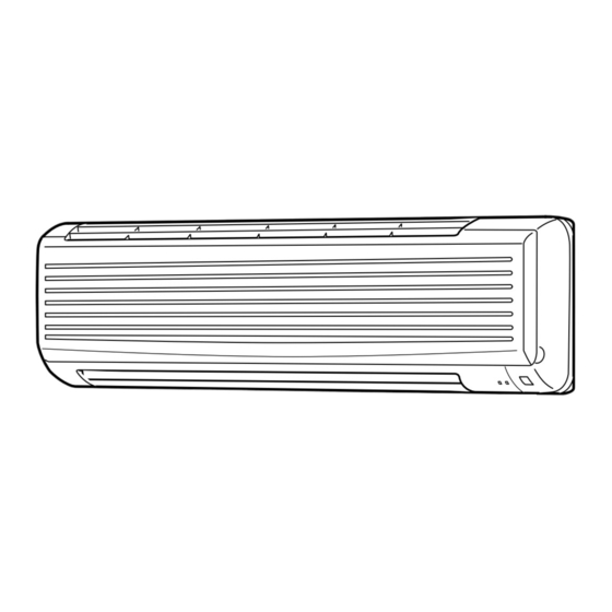
Page 6: Part Names And Functions
PART NAMES AND FUNCTIONS INDOOR UNIT MSC-A07WV - MSC-A09WV - MSC-A12WV - Front panel Air cleaning filter (White bellows type) Air inlet Deodorizing filter to Breaker (Gray sponge type) Power supply cord Panel Air filter Remote control receiving section Air outlet... -
Page 7: Outdoor Unit
Drainage hose Drainage hose Drain outlet Drain outlet MXZ-A18WV- Air inlet (Back and side) Air outlet Drain outlet ACCESSORIES MSC-A07WV- MUH-A07WV- MUH-A09WV- MSC-A09WV- MUH-A12WV- MSC-A12WV- <Outdoor unit: MUH type> <Indoor unit> Drain socket Installation plate Installation plate fixing screw 4 o 25 mm... -
Page 8: Remote Controller
MIN. button ECONO COOL MIN. ECONO COOL button (TIME SET button) RESET CLOCK CLOCK SET button RESET button VANE CONTROL button INDOOR/ OUTDOOR CORRESPONDENCE TABLE MSC-A07WV - MSC-A09WV - MSC-A12WV - OUTDOOR UNIT MUX-A19WV- MUX-A26WV- MUX-A10WV- MUX-A20WV- MUX-A25WV- A: MSC-A12WV-... -
Page 9: Indoor Units Combination
MXZ-A18WV - OUTDOOR UNIT MXZ-A18WV- 07+07 07+09 07+12 09+09 09+12 12+12 There is no combination other than this table. INDOOR UNITS COMBINATION MXZ-A18WV - NOTE: Electrical data is for outdoor unit only. Cooling capacity (kW) Outdoor unit Current Power Indoor units power consumption factor Total... - Page 10 SPECIFICATION Indoor model MSC-A07WV - MSC-A09WV - MSC-A12WV - Cooling Cooling Cooling Function Single phase Single phase Single phase Indoor unit power supply 230V,50Hz 230V,50Hz 230V,50Hz Capacity 474/372 /276 474/384 /306 Air flow(High/Med. /Low ) K /h 582/444 /324 Power outlet Running current 0.17...
- Page 11 Indoor model MSC-A07WV - MSC-A09WV - MSC-A12WV - Cooling Heating Cooling Heating Cooling Heating Function Single phase Single phase Single phase Indoor unit power supply 230V,50Hz 230V,50Hz 230V,50Hz Capacity Air flow(High/Med. /Low ) K /h 474/372 /276 510/420 /342 474/384 /306...
- Page 12 MSC-A07WV - MSC-A07WV - MSC-A12WV - Indoor model Cooling Cooling Cooling Function Single phase Single phase Single phase Indoor unit power supply 230V,50Hz 230V,50Hz 230V,50Hz 582/444 /324 Air flow (High/Med./Low) K /h 474/372 /276 474/372 /276 Capacity Power outlet 0.17 0.17...
- Page 13 Indoor model MSC-A09WV - Cooling Function Single phase Indoor unit power supply 230V,50Hz 474/384 /306 Air flow (High/Med./Low) K /h Capacity Power outlet 0.17 Running current Power input Power factor — Starting current 0.17 Fan motor current RC4V19-LA Model WHT-BLK 413 Winding "...
- Page 14 (Unit A ,B) Indoor model MSC-A12WV - Cooling Function Single phase 230V,50Hz Indoor unit power supply 582/444 /324 K /h Capacity Air flow (High/Med./Low) Power outlet Running current 0.19 Power input Power factor — Starting current 0.19 Fan motor current RC4V19-KA Model WHT-BLK 316...
- Page 15 (Unit C ,D) (Unit A ,B) Indoor model MSC-A09WV - MSC-A12WV - Cooling Cooling Function Single phase 230V,50Hz Single phase 230V,50Hz Indoor unit power supply Air flow (High/Med./Low) K /h 474/384 /306 582/444 /324 Capacity Power outlet Running current 0.17 0.19 Power input Power factor...
- Page 16 Outdoor model MXZ-A18WV - Single phase Outdoor unit power supply 230V,50Hz Indoor units number Total model name 24 Indoor units total capacity (Connectable) Total model name 24 indoor units total capacity (Simultaneous operation) Max. 30 (chargeless 20) Piping total length Max.
-
Page 17: Noise Criteria Curves
NOISE CRITERIA CURVES MSC-A09WV- MSC-A07WV- SPL(dB LINE SPL(dB LINE FAN SPEED FUNCTION FAN SPEED FUNCTION COOL COOL High High HEAT HEAT Test conditions. Test conditions, Cooling : DB27: WB19: Cooling : DB27: WB19: Heating : DB20: WB -: Heating : DB20:... - Page 18 MU-A12WV- MUH-A07WV- SPL(dB LINE SPL(dB LINE FUNCTION FUNCTION COOL COOL HEAT Test conditions, Test conditions, Cooling :DB35: WB24: Cooling :DB35: WB24: Heating :DB 7: WB 6: NC-70 NC-70 NC-60 NC-60 NC-50 NC-50 NC-40 NC-40 NC-30 NC-30 APPROXIMATE APPROXIMATE TERESHOLD OF TERESHOLD OF HEARING FOR HEARING FOR...
- Page 19 MUX-A19WV - MUX-A26WV - SPL(dB LINE FUNCTION SPL(dB LINE FUNCTION MUX-A20WV - COOL COOL MUX-A25WV - Test conditions. Test conditions. Cooling :DB35: WB24: Cooling :DB35: WB24: NC-70 NC-70 NC-60 NC-60 NC-50 NC-50 NC-40 NC-40 NC-30 NC-30 APPROXIMATE APPROXIMATE TERESHOLD OF TERESHOLD OF HEARING FOR HEARING FOR...
-
Page 20: Outlines And Dimensions
OUTLINES AND DIMENSIONS Unit: mm MSC-A07WV - 81.5 133.5 MSC-A09WV - Installation plate INDOOR UNIT Indoor unit 81.5 81.5 Wall hole Installation plate Liquid line 6.35-0.5m Gas line 9.52-0.43m Insulation 37 O.D Air in 21 I.D Drain hose (Connected part O,D) - Page 21 Unit: mm MU-A07WV - MUH-A07WV - REQUIRED SPACE MU-A09WV - MUH-A09WV - MU-A12WV - MUH-A12WV - OUTDOOR UNIT Air in Air in Drainage 3holes [33 Air out Service panel Liquid refrigerant pipe joint Refrigerant pipe (flared) [6.35 Gas refrigerant pipe joint Refrigerant pipe (flared) [9.52 (MU-A07/A09WV ) (MUH-A07/A09WV )
- Page 22 Unit: mm OUTDOOR UNIT REQUIRED SPACE MUX-A10WV- Air in Air in Drainage 3holes [33 Air out Service panel Liquid refrigerant pipe joint Refrigerant pipe (flared) [6.35 Gas refrigerant pipe joint Refrigerant pipe (flared) [9.52 MUX-A19WV- Open as a rule 500mm or more if the front and both sides are open 100mm or more...
- Page 23 Unit: mm OUTDOOR UNIT Open as a rule MUX-A20WV- 500mm or more if the front and both sides are open 100mm or more 200mm or more if 100mm or more Drainage there are obstacles 3holes {33 Air in to both sides Air in Open as a rule 500mm or more if the back,...
- Page 24 Unit: mm OUTDOOR UNIT Open as a rule 500mm or more if the front and both MUX-A26WV- sides are open 100mm or more 200mm or more if Drainage 100mm or more there are obstacles 3 holes Air in to both sides Air in Open as a rule Air out...
-
Page 25: Wiring Diagram
WIRING DIAGRAM MSC-A07WV - MSC-A09WV - MSC-A12WV - MODELS WIRING DIAGRAM INDOOR UNIT TO OUTDOOR UNIT TAB12 RT12 CONNECTING CN201 RT11 MUH OR MXZ TYPE NR11 CN202 MU OR MUX TYPE SR141 CN211 POWER LD103 ELECTRONIC CONTROL P.C. BOARD SUPPLY... - Page 26 MU-A07WV - MU-A09WV - MU-A12WV - MODELS WIRING DIAGRAM OUTDOOR UNIT FROM INDOOR UNIT CONNECTING DSAR CIRCUIT BREAKER NO COM POWER SUPPLY 230V 50Hz GRN/YLW SYMBOL NAME SYMBOL NAME SYMBOL NAME COMPRESSOR(INNER PROTECTOR) CONTACTOR COMPRESSOR CAPACITOR OUTDOOR FAN MOTOR(INNER FUSE) OUTDOOR FAN CAPACITOR DSAR TERMINAL BLOCK...
- Page 27 MUX-A10WV - MODEL WIRING DIAGRAM OUTDOOR UNIT POWER SUPPLY ~ / N 230V 50Hz S MC CIRCUIT BREAKER 21R1 FROM INDOOR UNIT No.A CONNECTING 21R2 FROM INDOOR UNIT No.B CONNECTING SYMBOL NAME SYMBOL NAME SYMBOL NAME COMPRESSOR CAPACITOR OUTDOOR FAN MOTOR(INNER FUSE) 21R1 SOLENOID COIL(A) OUTDOOR FAN CAPACITOR...
- Page 28 MUX-A19WV - MUX-A25WV - MODELS WIRING DIAGRAM OUTDOOR UNIT POWER SUPPLY 230V 50Hz CIRCUIT BREAKER CN90 OUTDOOR CONTROL X521 P.C. BOARD FROM INDOOR X522 UNIT A CONNECTING X522 X521 NR61 FROM INDOOR UNIT B CONNECTING CN91 2 3 4 MF61 SYMBOL NAME SYMBOL...
- Page 29 MUX-A20WV - MODEL WIRING DIAGRAM OUTDOOR UNIT...
- Page 30 MUX-A26WV - MODEL WIRING DIAGRAM OUTDOOR UNIT...
- Page 31 MODEL MXZ-A18WV- OUTDOOR UNIT TO INDOOR UNIT No.A CONNECTING DS61 TAB61 TAB63 TO INDOOR UNIT No.B CONNECTING F912 R64A R64B CIRCUIT BREAKER POWER NR63 TAB1 SUPPLY DS62 TAB62 230V 50Hz TAB2 CT61 TAB4 CN602 CN601 TAB64 CT761 ELECTRONIC CONTROL TAB65 TAB67 P.C.BOARD T801...
-
Page 32: Refrigerant System Diagram
REFRIGERANT SYSTEM DIAGRAM Unit:mm MSC-A07WV - MU-A07WV - MSC-A09WV - MU-A09WV - INDOOR UNIT OUTDOOR UNIT Refrigerant pipe [9.52 (with heat insulator) Stop valve (with service port) Muffler Indoor coil Indoor thermistor heat Outdoor exchanger RT12 heat Flared connection exchanger... -
Page 33: Indoor Unit
Unit:mm MSC-A07WV - MUH-A07WV - MSC-A09WV - MUH-A09WV - INDOOR UNIT OUTDOOR UNIT Refrigerant pipe [ 9.52 4-way valve (with heat insulator) Indoor coil Defrost Indoor Stop valve thermistor thermistor heat Outdoor (with service RT12 RT61 exchanger heat port) Flared connection... - Page 34 MAX. REFRIGERANT PIPING LENGTH Refrigerant piping Piping size O.D : mm Length of connecting pipe : m Model Max. length : m Outdoor unit Liquid Indoor unit MSC-A07WV - MU-A07WV - Gas 0 Gas 0.43 9.52 MSC-A09WV - 6.35 MU-A09WV - Liquid 0.5...
-
Page 35: Piping Preparation
Unit : mm MSC-A07WV- MUX-A10WV- INDOOR UNIT OUTDOOR UNIT Room Refrigerant pipe temperature Solenoid 9.52 thermistor (With insulation) valve RT11 Strainer Indoor Capillary tube Stop valve Muffler [3.0 x [1.4 x 1000 heat with service port UNIT A exchanger Flared connection... - Page 36 Unit : mm MSC-A07WV- MUX-A19WV- MSC-A12WV- INDOOR UNIT OUTDOOR UNIT Refrigerant pipe Room 12.7 temperature (With insulation) thermistor RT11 Indoor Stop valve Muffler heat with service port UNIT A exchanger MSC-A12WV Flared connection Indoor coil Compressor(A) Stop valve thermistor RT12...
- Page 37 MSX-A19WV- MAX.REFRIGERANT PIPING LENGTH & MAX. HEIGHT DIFFERENCE Indoor unit A Indoor unit B MSC-A12WV - E1 MSC-A07WV - E1 Outdoor unit MUX-A19WV - E1 UNIT No. Pipe length Height difference (H) No. of bends Max. limits ADDITIONAL REFRIGERANT CHARGE (R410A:g)
- Page 38 Unit : mm MSC-A09WV- MUX-A20WV- INDOOR UNIT OUTDOOR UNIT Refrigerant pipe Room 9.52 temperature (With insulation) thermistor RT11 Indoor Stop valve Muffler heat with service port UNIT A exchanger MSC-A09WV Flared connection Indoor coil Compressor(A) Stop valve thermistor RT12 Refrigerant pipe Capillary tube Strainer 6.35...
- Page 39 MSX-A20WV- MAX.REFRIGERANT PIPING LENGTH & MAX. HEIGHT DIFFERENCE Indoor unit A Indoor unit B Indoor unit C MSC-A09WV - E1 MSC-A09WV - E1 MSC-A09WV - E1 Outdoor unit MUX-A20WV - E1 UNIT No. Pipe length Height difference (H) No. of bends Max.
- Page 40 Unit : mm MSC-A12WV- MUX-A25WV- INDOOR UNIT OUTDOOR UNIT Refrigerant pipe Room 12.7 temperature (With insulation) thermistor RT11 Indoor Stop valve Muffler heat with service port UNIT A exchanger MSC-A12WV Flared connection Indoor coil Compressor(A) Stop valve thermistor RT12 Capillary tube Refrigerant pipe Strainer 6.35...
- Page 41 MSX-A25WV- MAX.REFRIGERANT PIPING LENGTH & MAX. HEIGHT DIFFERENCE Indoor unit A Indoor unit B MSC-A12WV - E1 MSC-A12WV - E1 Outdoor unit MUX-A25WV - E1 UNIT No. Pipe length Height difference (H) No. of bends Max. limits ADDITIONAL REFRIGERANT CHARGE (R410A:g) Refrigerant piping length (one way) Outdoor unit precharged...
- Page 42 MSC-A09WV- MUX-A26WV- Unit : mm MSC-A12WV- INDOOR UNIT OUTDOOR UNIT Refrigerant pipe Room {12.7 temperature Solenoid (With insulation) thermistor valve RT11 21RA Strainer Indoor Capillary tube Stop valve Muffler [3.0 x [1.4 x 1000 heat with service port UNIT A exchanger MSC-A12WV- E1 Flared connection...
- Page 43 MSX-A26WV- MAX.REFRIGERANT PIPING LENGTH & MAX. HEIGHT DIFFERENCE Indoor unit A Indoor unit B Indoor unit C Indoor unit D MSC-A12WV- E1 MSC-A12WV- E1 MSC-A09WV- E1 MSC-A09WV- E1 Outdoor unit MUX-A26WV- E1 UNIT No. Pipe length Height difference (H) No. of bends Total Total Max.
- Page 44 MXZ-A18WV - Unit:mm R.V. coil heating ON Discharge cooling OFF Compressor temperature Refrigerant flow in cooling thermistor Refrigerant flow in heating Muffler Stop valve (with service port) 4-way valve Gas pipe temperature B thermistor Indoor Muffler Unit B Indoor Gas pipe temperature Unit A A thermistor Stop valve...
-
Page 45: Performance Curves
PERFORMANCE CURVES MSC-A07WV - MU-A07WV - MUH-A07WV - MUX-A10WV - MUX-A25WV - MSC-A09WV - MU-A09WV - MUH-A09WV - MUX-A19WV - MUX-A26WV - MSC-A12WV - MU-A12WV - MUH-A12WV - MUX-A20WV - MXZ-A18WV - The standard data contained in these specifications apply only to the operation of the air conditioner under normal conditions, since operating conditions vary according to the areas where these units are installed. - Page 46 10.6 19.2 20.4 25.2 18.8 23.3 17.8 21.4 16.3 17.2 19.4 14.8 15.7 14.1 17.5 13.3 12.5 15.5 11.8 10.4 11.0 13.6 11.7 NOTE:The above curves are for the heating operation without any frost. 10-2.OUTDOOR LOW PRESSURE AND OUTDOOR UNIT CURRENT COOL operation Both indoor and outdoor unit are under the same temperature/humidity condition.
- Page 47 MU-A09WV - MU-A09WV - (kgf/F[Gauge])(MPa[Gauge]) 230V 230V 35(:) 35(:) 70(%) 70(%) Ambient temperature(˚C) Ambient temperature(˚C) Ambient humidity(%) Ambient humidity(%) MU-A12WV - MU-A12WV - (kgf/F[Gauge])(MPa[Gauge]) 230V 230V 35(:) 35(:) 70(%) 70(%) Ambient temperature(˚C) Ambient temperature(˚C) Ambient humidity(%) Ambient humidity(%) MUH-A07WV - MUH-A07WV - (kgf/F[Gauge])(MPa[Gauge]) 230V...
- Page 48 MUH-A12WV - MUH-A12WV - (kgf/F[Gauge])(MPa[Gauge]) 230V 230V 35 (:) 35(:) 70(%) 70(%) Ambient temperature(˚C) Ambient temperature(˚C) Ambient humidity(%) Ambient humidity(%) HEAT operation Condition indoor:Dry bulb temperature 20.0°C Outdoor:Dry bulb temperature 7,15,20°C Wet bulb temperature 14.5°C Wet bulb temperature 6,12,14.5°C MUH-A09WV - MUH-A07WV - 230V 230V...
- Page 49 MSC-A07WV - MUX-A10WV - MUX-A25WV - MSC-A09WV - MUX-A19WV - MUX-A26WV - MSC-A12WV - MUX-A20WV - 10-3.CAPACITY AND THE INPUT CURVES (ONE INDOOR UNIT WITH ONE OUTDOOR UNIT) 10.3 10.2 10.2 10.8 10.2 10-4.OUTDOOR LOW PRESSURE AND OUTDOOR UNIT CURRENT COOL operation Both indoor and outdoor unit are under same temperature/humidity condition.
- Page 50 MUX-A20WV- (kgf/F[Gauge])(MPa[Gauge]) Single operation (Unit A) (kgf/F[Gauge])(MPa[Gauge]) Single operation (Unit B or C) 230V 230V 230V 230V (˚C) (˚C) (˚C) (˚C) Ambient temperature(˚C) Ambient temperature(˚C) Ambient temperature(˚C) Ambient temperature(˚C) Ambient humidity(%) Ambient humidity(%) Ambient humidity(%) Ambient humidity(%) MUX-A25WV- Single operation (Unit A or B) (kgf/F[Gauge])(MPa[Gauge]) 230V 230V...
- Page 51 23.7 22.6 22.9 21.9 20.9 21.2 20.1 19.2 19.4 18.2 17.4 17.6 16.4 15.7 15.9 14.6 13.9 14.1 12.8 12.2 12.4 10.9 10.4 10.6 10-6. Capacity and input correction by inverter output frequency (OUTDOOR UNIT : MXZ-A18WV) NOTE 1 : Compressor running frequency at 33Hz (COOL) or 45Hz (HEAT). NOTE 2 : The dotted line on graphs connects the frequency range in normal operation shown by the full line and the frequency in test run shown by the point.
- Page 52 10-7. Outdoor low pressure and outdoor unit current 1. 07-class unit in single operation (OUTDOOR UNIT : MXZ-A18WV) NOTE:The unit of pressure has been changed to MPa on the international system of units(SI unit system). The converted score against the traditional unit system can be gotten according to the formula below. 1(MPa •...
- Page 53 2. 09-class unit in single operation (OUTDOOR UNIT : MXZ-A18WV) NOTE:The unit of pressure has been changed to MPa on the international system of units(SI unit system). The converted score against the traditional unit system can be gotten according to the formula below. 1(MPa •...
- Page 54 3. 12-class unit in single operation (OUTDOOR UNIT : MXZ-A18WV) NOTE:The unit of pressure has been changed to MPa on the international system of units(SI unit system). The converted score against the traditional unit system can be gotten according to the formula below. 1(MPa •...
- Page 55 PERFORMANCE DATA COOL operation (230V) MSC-A07WV - : MU-A07WV - CAPACITY : 2.3(kW) SHF : 0.74 INPUT : 710(W) DB( : ) OUTDOOR INDOOR INDOOR DB( : ) WB( : ) SHC SHF INPUT SHC SHF INPUT SHC SHF INPUT SHC SHF INPUT 2.70 1.51 0.56...
- Page 56 PERFORMANCE DATA COOL operation (230V) MSC-A07WV - : MU-A07WV - CAPACITY : 2.3(kW) SHF : 0.74 INPUT : 710(W) OUTDOOR DB( : ) INDOOR INDOOR DB( : ) WB( : ) SHC SHF INPUT SHC SHF INPUT SHC SHF INPUT 2.25 1.26 0.56...
- Page 57 PERFORMANCE DATA COOL operation (230V) MSC-A09WV - : MU-A09WV - CAPACITY : 2.55(kW) SHF : 0.70 INPUT : 780(W) DB( : ) OUTDOOR INDOOR INDOOR DB( : ) WB( : ) SHC SHF INPUT SHC SHF INPUT SHC SHF INPUT SHC SHF INPUT 3.00 1.56 0.52 2.87 1.49 0.52...
- Page 58 PERFORMANCE DATA COOL operation (230V) MSC-A09WV - : MU-A09WV - CAPACITY : 2.55(kW) SHF : 0.70 INPUT : 780(W) DB( : ) OUTDOOR INDOOR INDOOR DB( : ) WB( : ) SHC SHF INPUT SHC SHF INPUT SHC SHF INPUT 2.50 1.30 0.52 2.30 1.19 0.52 2.21 1.15 0.52...
- Page 59 PERFORMANCE DATA COOL operation (230V) MSC-A12WV - : MU-A12WV - CAPACITY : 3.45(kW) SHF : 0.67 INPUT : 1140(W) DB( : ) OUTDOOR INDOOR INDOOR DB( : ) WB( : ) SHC SHF INPUT SHC SHF INPUT SHC SHF INPUT SHC SHF INPUT 4.05 1.99 0.49 3.88 1.90 0.49...
- Page 60 PERFORMANCE DATA COOL operation (230V) MSC-A12WV - : MU-A12WV - CAPACITY : 3.45(kW) SHF : 0.67 INPUT : 1140(W) DB( : ) OUTDOOR INDOOR INDOOR DB( : ) WB( : ) SHC SHF INPUT SHC SHF INPUT SHC SHF INPUT 3.38 1.66 0.49 1117 3.11 1.52 0.49...
- Page 61 PERFORMANCE DATA COOL operation (230V) MSC-A07WV - : MUH-A07WV - CAPACITY : 2.3(kW) SHF : 0.74 INPUT : 710(W) DB( : ) OUTDOOR INDOOR INDOOR DB( : ) WB( : ) SHC SHF INPUT SHC SHF INPUT SHC SHF INPUT SHC SHF INPUT 2.70 1.51 0.56...
- Page 62 PERFORMANCE DATA COOL operation (230V) MSC-A07WV - : MUH-A07WV - CAPACITY : 2.3(kW) SHF : 0.74 INPUT : 710(W) DB( : ) OUTDOOR INDOOR INDOOR DB( : ) WB( : ) SHC SHF INPUT SHC SHF INPUT SHC SHF INPUT 2.25 1.26 0.56...
- Page 63 PERFORMANCE DATA COOL operation (230V) MSC-A09WV - : MUH-A09WV - CAPACITY : 2.55(kW) SHF : 0.70 INPUT : 780(W) DB( : ) OUTDOOR INDOOR INDOOR DB( : ) WB( : ) SHC SHF INPUT SHC SHF INPUT SHC SHF INPUT SHC SHF INPUT 3.00 1.56 0.52 2.87 1.49 0.52...
- Page 64 PERFORMANCE DATA COOL operation (230V) MSC-A09WV - : MUH-A09WV - CAPACITY : 2.55(kW) SHF : 0.70 INPUT : 780(W) DB( : ) OUTDOOR INDOOR INDOOR DB( : ) WB( : ) SHC SHF INPUT SHC SHF INPUT SHC SHF INPUT 2.50 1.30 0.52 2.30 1.19 0.52 2.21 1.15 0.52...
- Page 65 PERFORMANCE DATA COOL operation (230V) MSC-A12WV - : MUH-A12WV - CAPACITY : 3.40(kW) SHF : 0.67 INPUT : 1060(W) DB( : ) OUTDOOR INDOOR INDOOR DB( : ) WB( : ) SHC SHF INPUT SHC SHF INPUT SHC SHF INPUT SHC SHF INPUT 4.00 1.96 0.49 3.83 1.87 0.49...
- Page 66 PERFORMANCE DATA COOL operation (230V) MSC-A12WV - : MUH-A12WV - CAPACITY : 3.40(kW) SHF : 0.67 INPUT : 1060(W) DB( : ) OUTDOOR INDOOR INDOOR DB( : ) WB( : ) SHC SHF INPUT SHC SHF INPUT SHC SHF INPUT 3.33 1.63 0.49 1039 3.06 1.50 0.49...
- Page 67 PERFORMANCE DATA HEAT operation (230V) MSC-A07WV - : MUH-A07WV - CAPACITY : 2.5 kW INPUT : 690 W OUTDOOR WB(;) INDOOR DB(;) INPUT INPUT INPUT INPUT INPUT INPUT INPUT 1.58 1.90 2.23 2.55 2.88 3.18 3.50 1.50 1.80 2.13 2.43 2.75...
- Page 68 PERFORMANCE DATA COOL operation (230V) MSC-A07WV - (Single) : MUX-A10WV - CAPACITY : 2.4(kW) SHF : 0.74 INPUT : 760(W) OUTDOOR DB( : ) INDOOR INDOOR DB( : ) WB( : ) SHC SHF INPUT SHC SHF INPUT SHC SHF INPUT SHC SHF INPUT 2.82 1.58 0.56...
- Page 69 PERFORMANCE DATA COOL operation (230V) MSC-A07WV - (Single) : MUX-A10WV - CAPACITY : 2.4(kW) SHF : 0.74 INPUT : 760(W) DB( : ) OUTDOOR INDOOR INDOOR DB( : ) WB( : ) SHC SHF INPUT SHC SHF INPUT SHC SHF INPUT 2.35 1.32 0.56...
- Page 70 PERFORMANCE DATA COOL operation (230V) MSC-A07WV - (Single : Room B) : MUX-A19WV - CAPACITY : 2.4(kW) SHF : 0.74 INPUT : 820(W) DB( : ) OUTDOOR INDOOR INDOOR DB( : ) WB( : ) SHC SHF INPUT SHC SHF INPUT...
- Page 71 PERFORMANCE DATA COOL operation (230V) MSC-A07WV - (Single : Room B) : MUX-A19WV - CAPACITY : 2.4(kW) SHF : 0.74 INPUT : 820(W) DB( : ) OUTDOOR INDOOR INDOOR DB( : ) WB( : ) SHC SHF INPUT SHC SHF INPUT SHC SHF INPUT 2.35 1.32 0.56...
- Page 72 PERFORMANCE DATA COOL operation (230V) MSC-A12WV - (Single : Room A) : MUX-A19WV - CAPACITY : 3.5(kW) SHF : 0.73 INPUT : 1320(W) OUTDOOR DB( : ) INDOOR INDOOR DB( : ) WB( : ) SHC SHF INPUT SHC SHF INPUT SHC SHF INPUT SHC SHF INPUT 4.11 2.25 0.55...
- Page 73 PERFORMANCE DATA COOL operation (230V) MSC-A12WV - (Single : Room A) : MUX-A19WV - CAPACITY : 3.5(kW) SHF : 0.73 INPUT : 1320(W) DB( : ) OUTDOOR INDOOR INDOOR DB( : ) WB( : ) SHC SHF INPUT SHC SHF INPUT SHC SHF INPUT 3.43 1.88 0.55 1294...
- Page 74 PERFORMANCE DATA COOL operation (230V) MSC-A09WV - (Single : Room A) : MUX-A20WV - CAPACITY : 2.6(kW) SHF : 0.75 INPUT : 850(W) DB( : ) OUTDOOR INDOOR INDOOR DB( : ) WB( : ) SHC SHF INPUT SHC SHF INPUT SHC SHF INPUT SHC SHF INPUT 3.06 1.74 0.57...
- Page 75 PERFORMANCE DATA COOL operation (230V) MSC-A09WV - (Single : Room A) : MUX-A20WV - CAPACITY : 2.6(kW) SHF : 0.75 INPUT : 850(W) DB( : ) OUTDOOR INDOOR INDOOR DB( : ) WB( : ) SHC SHF INPUT SHC SHF INPUT SHC SHF INPUT 2.55 1.45 0.57 2.34 1.33 0.57...
- Page 76 PERFORMANCE DATA COOL operation (230V) MSC-A09WV - (Single : Room B) : MUX-A20WV - CAPACITY : 2.9(kW) SHF : 0.71 INPUT : 1110(W) DB( : ) OUTDOOR INDOOR INDOOR DB( : ) WB( : ) SHC SHF INPUT SHC SHF INPUT SHC SHF INPUT SHC SHF INPUT 3.41 1.82 0.53...
- Page 77 PERFORMANCE DATA COOL operation (230V) MSC-A09WV - (Single : Room B) : MUX-A20WV - CAPACITY : 2.9(kW) SHF : 0.71 INPUT : 1110(W) DB( : ) OUTDOOR INDOOR INDOOR DB( : ) WB( : ) SHC SHF INPUT SHC SHF INPUT SHC SHF INPUT 2.84 1.51 0.53 1088...
- Page 78 PERFORMANCE DATA COOL operation (230V) MSC-A12WV - (Single) : MUX-A25WV - CAPACITY : 3.5(kW) SHF : 0.73 INPUT : 1340(W) DB( : ) OUTDOOR INDOOR INDOOR DB( : ) WB( : ) SHC SHF INPUT SHC SHF INPUT SHC SHF INPUT SHC SHF INPUT 4.11 2.25 0.55 1072...
- Page 79 PERFORMANCE DATA COOL operation (230V) MSC-A12WV - (Single) : MUX-A25WV - CAPACITY : 3.5(kW) SHF : 0.73 INPUT : 1340(W) DB( : ) OUTDOOR INDOOR INDOOR DB( : ) WB( : ) SHC SHF INPUT SHC SHF INPUT SHC SHF INPUT 3.43 1.88 0.55 1313 3.15 1.72 0.55...
- Page 80 PERFORMANCE DATA COOL operation (230V) MSC-A09WV - (Single : Room C ) : MUX-A26WV - CAPACITY : 2.75(kW) SHF :0.73 INPUT : 1050(W) OUTDOOR DB( : ) INDOOR INDOOR DB( : ) WB( : ) SHC SHF INPUT SHC SHF INPUT SHC SHF INPUT SHC SHF INPUT 3.23 1.76 0.55...
- Page 81 PERFORMANCE DATA COOL operation (230V) MSC-A09WV - (Single : Room C ) : MUX-A26WV - CAPACITY : 2.75(kW) SHF : 0.73 INPUT : 1050(W) DB( : ) OUTDOOR INDOOR INDOOR DB( : ) WB( : ) SHC SHF INPUT SHC SHF INPUT SHC SHF INPUT 2.70 1.47 0.55 1029...
- Page 82 PERFORMANCE DATA COOL operation (230V) MSC-A12WV - (Single : Room A) : MUX-A26WV - CAPACITY : 3.4(kW) SHF : 0.77 INPUT : 1220(W) DB( : ) OUTDOOR INDOOR INDOOR DB( : ) WB( : ) SHC SHF INPUT SHC SHF INPUT SHC SHF INPUT SHC SHF INPUT 4.00 2.37 0.59...
- Page 83 PERFORMANCE DATA COOL operation (230V) MSC-A12WV - (Single : Room A) : MUX-A26WV - CAPACITY : 3.4(kW) SHF : 0.77 INPUT : 1220(W) DB( : ) OUTDOOR INDOOR INDOOR DB( : ) WB( : ) SHC SHF INPUT SHC SHF INPUT SHC SHF INPUT 3.33 1.98 0.59 1196...
-
Page 84: Microprocessor Control
MICROPROCESSOR CONTROL MSC-A07WV - MU-A07WV - MUH-A07WV - MUX-A10WV - MUX-A25WV - MSC-A09WV - MU-A09WV - MUH-A09WV - MUX-A19WV - MUX-A26WV - MSC-A12WV - MU-A12WV - MUH-A12WV - MUX-A20WV - Once the operation mode are set, the same operation mode can be repeated by simply turning the OPERATE/STOP (ON/OFF) button ON. - Page 85 3. Coil frost prevention Temperature control When the indoor coil thermistor RT12 reads 4°C or below(MSC-A07/A09WV) / 0°C or below(MSC-A12WV) for 5 minutes, the coil frost prevention mode starts. The indoor fan operates at the set speed and the compressor stops for 5 minutes. After that, if RT12 still reads below 4°C (MSC-A07/A09WV) / 0°C (MSC-A12WV), this mode is prolonged until the RT12 reads over 4°C (MSC-A07/A09WV) / 0°C (MSC-A12WV).
- Page 86 Operation time chart Example Thermostat Indoor fan Outdoor fan Compressor 4 min. 8 min. 3 min. 1 min. 4. Coil frost prevention The operation is as same as coil frost prevention during COOL operation.(Refer to 11-1.3.) However when coil frost prevention works while the indoor fan is OFF, its speed becomes set speed. <...
- Page 87 (3) Warm air control. When the following any condition of 1 (a. ~ c.) and the condition of 2 are satisfied at the same time, warm air control works. 1 a.) When outdoor unit starts operating inHEAT mode. b.) When cold air prevention has been released. c.) When defrosting has been finished 2 When the temperature of indoor coil thermistor RT12 is less than 37°C.
- Page 88 4. Defrosting <MUH-A07/A09/A12WV> Defrosting of outdoor heat exchanger is controlled by DEICER P.C. board, with detection by the defrost thermistor RT61. (1) Starting conditions of defrost When all conditions of a) ~ c) are satisfied, the defrosting operation starts. a) The compressor cumulative operation time exceeds 40 minutes without the defrosting operation working. b) RT61 reads - 3°C or less.
- Page 89 5. R.V. coil control <MUH-A07/A09/A12WV> Heating · · · · · ON Cooling · · · · · OFF Dry · · · · · · · · OFF When operation starts, the 4-way valve reverses for 5 seconds right before start-up of the compressor. Operation time chart (HEAT) (COOL/DRY)
- Page 90 (4) The initial set temperature is decided by the initial room temperature. Initial room temperature Mode Initial set temperature MU & MUX type MUH type 26: or more 26: or more COOL mode of "I FEEL CONTROL" Initial room temperature 25: or more, 25: or more, less than 26:...
- Page 91 11-6. FAN MOTOR CONTROL (1) Rotational frequency feedback control The indoor fan motor is equipped with a rotational frequency sensor, and outputs signal to the microprocessor to feedback the rotational frequency. Comparing the current rotational frequency with the target rotational frequency (High,Med.,Low), the microprocessor controls SR141 and adjusts fan motor electric current to make the current rotational frequency close to the target rotational frequency.
- Page 92 < > (7) Cold air prevention in HEAT operation MUH-A07/A09/A12WV When any of the following conditions occurs in HEAT operation, the horizontal vane angle changes to Angle 1 automat- ically to prevent cold air blowing on users. Compressor is not operating. Defrosting is performed.
- Page 93 (4) Press HR. and MIN. button to set the timer. Time setting is 10-minute units. HR. and MIN. button will work when “ ” or “ ” mark is flashing. These marks disappear in 1 minute. After setting the ON timer, check that OPERATION INDICATOR lamp of the indoor unit lights. NOTE1 : Be sure to place the remote controller at the position where its signal can reach the air conditioner even during TIMER operation, or the set time may deviate within the range of about 10 minutes.
- Page 94 11-10. OUTDOOR UNIT ACTUATOR CONTROL MUX-A10WV - MUX-A19WV - MUX-A25WV - INDOOR UNIT INDOOR UNIT ACTUATOR ACTUATOR – COMPRE- COMPRE- – SSOR SSOR – – ANY UNIT ON ANY UNIT ON OUTDOOR OUTDOOR MF61 MF61 FAN MOTOR FAN MOTOR ON (CLOSE) MUX-A26WV - (BALANCE) INDOOR UNIT...
- Page 95 11-11 INVERTER MULTI SYSTEM CONTROL MXZ-18WV - Output signal Input signal Compressor Compressor Compressor power primary secondary factor current current Indoor unit microprocessor Outdoor unit control microprocessor Drive SSR61 circuit Transistor module Fin temperature thermistor RT65 Comp. Discharge temperature x 61 thermistor x 62 RT61...
- Page 96 11-11-1. INVERTER MAIN POWER SUPPLY CIRCUIT NOISE FILTER P.C.BOARD ELECTRONIC CONTROL P.C. BOARD R64A/R64B DS61/DS62 L61/L62 CT761 POWER SUPPLY CT61 11-11-2. Outline of main power supply circuit 1. At the start of operation Rush current is generated the instant the electricity is turned on to the main power supply circuit to operate the compressor.
- Page 97 5. IPM Six power transistors that outputs the direct current waveform as three-phase alternating current waveform, the driving circuit which operates the power transistors, and the overcurrent detecting circuit which protects the power transistors are built into the IPM. It can simplify and miniaturize the control circuit. 6.AFM [Active Filter Module] The circuit that detects power supply voltage waveform, the circuit that detects the current flowing in module, the switching element that short-circuits between plus and minus pole of direct-current circuit, and the switching element driving current...
- Page 98 11-13 LEV control Linear expansion valve (LEV) is controlled by "Thermostat ON" commands given from each unit. Indoor unit status LEV opening Stop of all indoor unit Opening before stop 500 pulse in 15 minutes When outdoor unit is operating, COOL : 5 pulse (full closed) some indoor units stop and HEAT : 59 pulse (slightly opened)
- Page 99 Difference in Difference in Standard opening (pulse) capacity operation number Code2 Code3 COOL HEAT Capacity code Indoor unit <Correction> COOL HEAT 1 Suction super heat (MIN gas pipe temperature thermistor - Evaporation temperature thermistor) • • 2 Each correction w 1 •...
- Page 100 (3) LEV opening correction by discharge temperature When LEV correction output is 0 pulse by the suction super heat at COOL or DRY operation, or HEAT operating, correct LEV is corrected according to the following table. The target discharge temperature is determined according to frequency zone and number of operation unit of the compressor.
- Page 101 11-16.Discharge temperature protection control This protection controls the compressor ON/OFF and operation frequency according to temperature of the discharge temp. thermistor. (1) Compressor ON/OFF When temperature of the discharge temp. thermistor exceeds 116;, the control stops the compressor. When temperature of the discharge temp. thermistor is 80; or less, the controls starts the compressor. (2) Compressor operation frequency When temperature of the discharge temp.
-
Page 102: Service Functions
SERVICE FUNCTIONS MSC-A07WV - MU-A07WV - MUH-A07WV - MUX-A10WV - MUX-A25WV - MSC-A09WV - MU-A09WV - MUH-A09WV - MUX-A19WV - MUX-A26WV - MSC-A12WV - MU-A12WV - MUH-A12WV - MUX-A20WV - MXZ-A18WV - < > 12-1. COMPULSORY DEFROSTING MODE FOR SERVICE MUH-A07/A09/A12WV By short circuit of the connector JPDS and JPSG on the outdoor deicer P.C. - Page 103 How to set the remote controller exclusively for particular indoor unit After you turn the breaker ON, the first remote controller that sends the signal to the indoor unit will be regarded as the remote controller for the indoor unit. The indoor unit will only accepts the signal from the remote controller that has been assigned to the indoor unit once they are set.
-
Page 104: Troubleshooting
Therefore, the special counter-measures are required to prevent the main voltage-drop or the rush of the starting current by adding system that allows the units to start one by one. TROUBLESHOOTING MSC-A07WV - MU-A07WV - MUH-A07WV - MUX-A10WV -... - Page 105 13-2. Instruction of troubleshooting MSC-A07WV - MU-A07WV - MUH-A07WV - MUX-A10WV - MUX-A25WV - MSC-A09WV - MU-A09WV - MUH-A09WV - MUX-A19WV - MUX-A26WV - MSC-A12WV - MU-A12WV - MUH-A12WV - MUX-A20WV - Start Indoor unit OPERATION Indoor unit Indoor unit Indoor unit operates.
- Page 106 MXZ-A18WV - Operation start Check the outdoor unit LED indicator. LED 1 or LED 2 Both LED 1 and has blinked. LED 2 lighting J Check of power supply Refer to indicator list See page 119. on page 108, 109. •...
- Page 107 13-3. Troubleshooting check table • The following indication does not depend on the shape of lamp. flashing Operation Indicator · Flashing of the OPERATION INDICATOR lamp (on the left-hand side) indicates possible abnormalities. · The OPERATION INDICATOR lamp (on the left-hand side) is lighting during normal operation. Before taking measures, make sure that the symptom reappears, for accurate troubleshooting.
- Page 108 MXZ-A18WV - <OUTDOOR UNIT> LED 1 (Red) LED 2 (Yellow) Error mode Lighting Lighting Normal Symptom: Outdoor unit does not operate. Indication Abnormal point Detecting method Check points LED 1 LED 2 (Red) (Yellow) When the drain abnormality is detected in the indoor unit and the indoor •...
- Page 109 8 times Active filter module protection When active filter module self-protection has been performed. Lighting 9 times Service mode When operating unit with compressor relay connector disconnected. 13-4. Trouble criterion of main parts MSC-A07WV - MSC-A09WV - MSC-A12WV - Part name Check method and criterion Figure Room Measure the resistance with a tester.
- Page 110 MU-A07WV - MUH-A07WV - MU-A09WV - MUH-A09WV - MU-A12WV - MUH-A12WV - Part name Check method and criterion Figure Measure the resistance with a tester. Defrost (Part temperature –10°C ~ 40°C) thermistor Normal Abnormal (RT63) MUH-A07/A09/A12WV Open or short-circuit <MUH- 5kΩ...
- Page 111 MUX-A10WV - MUX-A19WV - MUX-A20WV - MUX-A25WV - MUX-A26WV - Part name Check method and criterion Figure Measure the resistance between the terminals with a tester. MUX-A10WV (Coil wiring temperature -10°C ~ 40°C) Outdoor fan motor Normal Abnormal (MF, MF61) MUX-A10WV MUX-A19WV MUX-A20WV...
- Page 112 When OPERATION INDICATOR lamp flashes 3-time. Indoor fan motor doesn’t operate. A A Check of indoor fan motor Turn OFF the power supply. Check connector CN211 visually. Is soldered point of the Reconnect the lead wires. Resolder it. Are lead wires connected? connector correctly soldered? Disconnect lead wires from connector CN211 on indoor electronic control P.C.
- Page 113 The unit doesn’t operate with the remote controller. Also, the OPERATION INDICATOR lamp doesn’t light up by pressing the EMERGENCY OPERATION switch. C C Check of indoor electronic control P.C. board Check the both “parts side” and “pattern side” of indoor electronic control P.C. board visually.
- Page 114 Compressor and/or outdoor fan doesn’t operate. D D Check of outdoor unit <MUX-A19/A20/A25/A26WV> Start Is there 230V AC Check the power supply between L - N on the TB1 and connecting wire. of outdoor unit? Press the EMERGENCY OPEERATION switch of all indoor units.
- Page 115 Compressor and/or outdoor fan motor doesn’t stop. E E Check of outdoor unit <MU-A07/A09/A12WV> Start Turn OFF the power supply. After 1 minute, turn ON power supply again. Is there 230V AC between COM on the Is there 12V DC between Does compressor or Replace the compressor compressor contactor (52C) and N on the...
- Page 116 Unit operates COOL mode even if it is set to HEAT mode. w First, measure the resistance of R.V. coil to confirm it is disconnected or is not short-circuit. F F Check of R.V. coil <MUH-A07/A09/A12WV> Turn ON the power supply and operate the indoor unit in HEAT mode by pressing the EMERGENCY OPERATION switch.
- Page 117 When OPERATION INDICATOR lamp flashes 0.5-second intervals or 1-time. Outdoor unit does not operate. <MUH-A07/A09/A12WV> G G How to check mis-wiring and serial signal error 1 Set the switch(SW2-2) on indoor electronic control P.C. board to MU or MUX type, when the outdoor unit is MU or MUX type. If the setting is MUH or MXZ type, the unit does not work.
- Page 118 When OPERATION INDICATOR lamp flashes 6-time. Thermistors in the outdoor unit are abnormal. H H Check of outdoor thermistor <MUH-A07/A09/A12WV> Start Replace the deicer P.C. board. Defrost thermistor (RT61) Reconnect CN661. Measure Turn ON the power resistance Turn OFF the Is the resistance of supply and press Does the unit operate...
- Page 119 Outdoor unit does not operate. (LED display: display OFF) J J Check of power supply <MXZ-A18WV> Start Check the connecting of main circuit parts . Turn on power supply Is there voltage of 230V AC in the Check the power supply cable. power supply terminal block? Is there voltage of 230V AC across the Replace the noise...
- Page 120 The cooling operation or heating operation does not operate. (LED display: Both LED1 and LED2 lighting) L L Check of R. V. coil <MXZ-A18WV> • When heating operation does not work. Start 1. Disconnect the lead wire leading to the compressor. 2.
- Page 121 • When cooling, heat exchanger of non-operating indoor unit frosts. • When heating, non-operating indoor unit get warm. LED display: LED1 LED2 M M Check of LEV <MXZ-A18WV> Lighting Lighting 6 time Goes out Start Turn on power supply to the outdoor unit after checking LEV coil is mounted to the LEV body securely.
- Page 122 • When thermistor is abnormal. (When the LED display is a table below.) <MXZ-A18WV> O O Check of outdoor unit thermistor Start Abnormal Disconnect the connector in the outdoor electronic control P. C. board (see below table), Replace the thermistor and measure the resistance of thermistor to check whether the thermistor is normal or not.
- Page 123 Q Q The other cases <MXZ-A18WV> Indoor unit dose not operate. (different modes) • When you try to run two indoor unit simultaneously, one for cooling and the other for heating, the unit which transmits signal to the outdoor units earlier decides the operation mode. The other unit indicates as shown in the figure below.
- Page 124 TEST POINT DIAGRAM AND VOLTAGE MSC-A07WV - MSC-A09WV - MSC-A12WV - Indoor electronic control P.C. board Fuse 250V AC 3.15A Indoor fan motor 230 V AC 12V DC Power supply input 230 V AC Varistor (NR11) R132 Indoor coil thermistor (RT12)
- Page 125 MUH-A07WV - MUH-A09WV - MUH-A12WV - Outdoor deicer P.C. board CN711 CN721 Power supply input Outdoor fan motor R.V. coil 230V AC 230V AC 230V AC NR61 Varistor Fuse 2A/250V R601 5~10VDC Defrost interval time short pin (JPDS, JPSG) (Refer to page 102.) Jumper wire for change in defrost setting...
- Page 126 MUX-A19WV - MUX-A20WV - MUX-A25WV - MUX-A26WV - Outdoor control P.C. board To indoor unit B Solenoid coil 21R2 To indoor unit D Solenoid coil 21R4 To fan capacitor To indoor unit A To indoor unit C Solenoid coil 21R1 Solenoid coil 21R3 To solenoid coil 21RA To fan motor...
- Page 127 MXZ-A18WV - Outdoor Electronic control P.C. board Defrost temperature thermistor (RT62) Evaporation temperature thermistor (RT63) Gas pipe temperature thermistor (RT6A,6B) High-pressure protection thermistor (RT68) Fin temperature thermistor (RT65) Discharge temperature thermistor (RT61) 90 100 110 120 -20 -10 10 20 30 40 10 20 30 40 50 60 70 80 Temperature(:) Temperature(:)
- Page 128 MXZ-A18WV - Outdoor Noise filter P.C.board F912 FUSE 230V AC 50Hz 3.15A/250V Input NR63 VARISTOR 230V AC 50Hz Output CN912 R.V. Coil 230V AC CN911 Outdoor Fan Fan speed “High” 230V AC CN911 Outdoor Fan Fan speed “Low” 230V AC...
-
Page 129: Disassembly Instructions
1Hold the sleeve, and 2Pull the terminal while pull out the terminal pushing the locking slowly. lever. NOTE : These photos are MS-A09WV. 14-1. MSC-A07WV - MSC-A09WV - MSC-A12WV - Other models are almost the INDOOR UNIT same as MS-S09WV. OPERATING PROCEDURE PHOTOS 1. - Page 130 OPERATING PROCEDURE PHOTOS Vane motor 3. Removing the electrical box Indoor coil thermistor Photo 3 connector (1) Remove the front panel. (Refer to 1.) connector (2) Remove the electrical cover. (Refer to 2.) Screw of the (3) Remove the V.A. clamp. (Refer to 2.) electrical box (4) Remove the cord clamp.
- Page 131 14-2. MU-A07WV - MU-A09WV - MU-A12WV - OUTDOOR UNIT OPERATING PROCEDURE PHOTOS 1. Removing the cabinet Photo 1 (1) Remove the screws of the top panel. Screws of the front panel and motor support (2) Remove the screw of the service panel. (3) Remove the screws of the cabinet.
- Page 132 OPERATING PROCEDURE PHOTOS 3. Removing the propeller fan and the outdoor fan Photo 5 motor Lead clamps (1) Remove the cabinet. (Refer to 1.) Screws of the (2) Remove the propeller fan nut. Outdoor outdoor fan motor Hook (3) Remove the propeller fan. fan motor NOTE : Loose the propeller fan in the rotating direction for connector...
- Page 133 14-3. MUH-A07WV - MUH-A09WV - MUH-A12WV - OUTDOOR UNIT OPERATING PROCEDURE PHOTOS 1. Removing the cabinet Photo 1 Screws of the front panel and motor support (1) Remove the screws of the top panel. (2) Remove the screw of the service panel. (3) Remove the screws of the cabinet.
- Page 134 OPERATING PROCEDURE PHOTOS 3. Removing the propeller fan and the outdoor fan Photo 5 motor Lead clamps (1) Remove the cabinet. (Refer to 1.) Screws of the (2) Remove the propeller fan nut. Outdoor Hook outdoor fan motor (3) Remove the propeller fan. fan motor NOTE : Loose the propeller fan in the rotating direction for Propeller fan...
- Page 135 14-4. MUX-A10WV - OUTDOOR UNIT OPERATING PROCEDURE PHOTOS 1. Removing the cabinet Photo 1 (1) Remove the screws of the top panel. Set screws of the front panel (2) Remove the screw of the service panel. Screws and motor support (3) Remove the screws of the cabinet.
- Page 136 OPERATING PROCEDURE PHOTOS 3. Removing the propeller fan and the outdoor fan Photo 5 motor (1) Remove the cabinet. (Refer to 1.) (2) Remove the propeller fan nut. Screws of the Screws of the (3) Remove the propeller fan. solenoid coil solenoid coil NOTE : Loose the propeller fan in the rotating direction for (21R)
- Page 137 14-5. MUX-A19WV - MUX-A20WV - MUX-A25WV - MUX-A26WV - OUTDOOR UNIT NOTE : These photos are MUX-A20WV. Other models are almost the same as MUX-A20WV. OPERATING PROCEDURE PHOTOS 1.Removing the cabinet Photo 1 Top panel (1) Remove the screws of the service panel. (2) Remove the screws of the top panel.
- Page 138 OPERATING PROCEDURE PHOTOS 2. Removing the relay panel Photo 4 (1) Remove the cabinet. (Refer to 1) (2) Disconnect the following connectors. Solenoid coil connector . Outdoor fan motor Set screws of the (21RA, 21RB, 21R1, . Only MUX-20WV outdoor fan motor 21R2, 21R3, 21R4) Solenoid coil (21RB, 21R3, 21R4) .
- Page 139 OPERATING PROCEDURE PHOTOS 5. Removing the compressor (A, B) Photo 5 (1) Remove the cabinet. (Refer to 1.) (2) Remove the relay panel. (3) Remove the soundproof felt. (4) Remove the terminal cover on the compressor. Terminal cover (5) Disconnect lead wires from the compressor. Suction pipe (6) Recover gas from the refrigerant circuit.
- Page 140 14-6. MXZ-A18WV - OUTDOOR UNIT OPERATING PROCEDURE PHOTOS 1. Removing the cabinet. Photo 1 1. Removing the cabinet. (1) Remove the screws of the top panel. (2) Remove the top panel. (3) Remove the screw of the service panel. (4) Remove the service panel. (5) Remove the screws of the front panel.
- Page 141 OPERATING PROCEDURE PHOTOS 3. Removing the Outdoor Electronic control P.C. board. Photo 4 Screws of the cover (1) Remove the top panel, service panel and front panel. (2) Remove the connector coming out of the compressor. Screws of fan motor (3) Remove the compressor connector, compressor relay connector on the electronic control P.C.
- Page 142 OPERATING PROCEDURE PHOTOS 5. Removing the thermistor Photo 7 Discharge temperature thermistor, defrost temperature, evaporator temperature, high pressure protector, High pressure protector thermistor gas pipe temperature A and gas pipe temperature B (1) Remove the top panel, service panel, front panel. (2) Remove Indoor/outdoor connecting wire and power supply Defrost cable.
- Page 143 OPERATING PROCEDURE PHOTOS 6. Removing the compressor/4-way valve Photo 10 (1) Collect refrigerant from refrigerant circuit. Caution: If collecting has not been done enough, refrigerating machine oil may spout out or harmful substance may be generated during welding work. (2) Remove Indoor/outdoor connecting wire and power supply cable.
-
Page 144: Parts List
PARTS LIST MSC-A07WV - (WH) MSC-A09WV - (WH) MSC-A12WV - (WH) 15-2. ACCESSORY AND 15-1. INDOOR UNIT STRUCTURAL PARTS REMOTE CONTROLLER 1 (W) 10(W) 8 (See page 127.) 7 (See page 127.) 6 (W) (W) These figures show about MSC-A12WV. - Page 145 MSC-A07WV - (WH) MSC-A09WV - (WH) MSC-A12WV - (WH) 15-4. INDOOR UNIT HEAT EXCHANGER 15-3. INDOOR UNIT ELECTRICAL PARTS AND FUNCTIONAL PARTS 21 (W) SLEEVE BEARING ROOM TEMPERATURE THERMISTOR (W)These figures show about MSC-A12WV. VARISTOR FUSE 15-3. INDOOR UNIT ELECTRICAL PARTS AND FUNCTIONAL PARTS Part number that is circled is not shown in the illustration.
- Page 146 MU-A07WV - MU-A09WV - MU-A12WV - 15-5. OUTDOOR UNIT STRUCTURAL PARTS Part number that is circled is not shown in the illustration. Q'ty/unit Symbol in Wiring Part No. Part name Remarks MU-A07WV- MU-A09WV- MU-A12WV- Diagram E02 336 630 OUTDOOR HEAT EXCHANGER E02 336 232 CABINET E02 336 521...
- Page 147 MU-A07WV - MU-A09WV - MU-A12WV - 15-6. OUTDOOR UNIT ELECTRICAL PARTS AND FUNCTIONAL PARTS Part numbers that are circled are not shown in the illustration. Q'ty/unit Symbol in Wiring Remarks Part name Part No. MU-A07WV- MU-A09WV- MU-A12WV- Diagram E02 665 501 PROPELLER FAN E02 676 301 OUTDOOR FAN MOTOR...
- Page 148 MUH-A07WV - MUH-A09WV - MUH-A12WV - 15-7. OUTDOOR UNIT STRUCTURAL PARTS Part numbers that are circled are not shown in the illustration. Q'ty/unit Symbol in Wiring Remarks Remarks Part name Part No. MUH-A07WV- MUH-A09WV- MUH-A12WV- Diagram E02 679 630 OUTDOOR HEAT EXCHANGER E02 628 630 OUTDOOR HEAT EXCHANGER E02 336 232...
- Page 149 MUH-A07WV - MUH-A09WV - MUH-A12WV - 15-9. ACCESSORY 15-8. OUTDOOR UNIT ELECTRICAL PARTS AND FUNCTIONAL PARTS 15-8. OUTDOOR UNIT ELECTRICAL PARTS AND FUNCTIONAL PARTS Part numbers that are circled are not shown in the illustration. Q'ty/unit Symbol in Wiring Remarks Part name Part No.
- Page 150 MUX-A10WV - 15-10. OUTDOOR UNIT STRUCTURAL PARTS Part numbers that are circled are not shown in the illustration. Q'ty/unit Symbol Part No. in Wiring Part name Remarks MUX-A10WV- Diagram E02 755 630 OUTDOOR HEAT EXCHANGER E02 336 232 CABINET E02 336 521 GRILLE(OUT) E02 742 900 COMPRESSOR...
- Page 151 MUX-A10WV - 15-11. OUTDOOR UNIT ELECTRICAL PARTS AND FUNCTIONAL PARTS Q'ty/unit Symbol in Wiring Remarks Part name Part No. MUX-A10WV- Diagram PROPELLER FAN E02 665 501 E02 677 301 OUTDOOR FAN MOTOR RA6V33- TERMINAL BLOCK E02 056 374 OUTDOOR FAN CAPACITOR 2.0+ /440V AC E02 664 351 E02 755 341...
- Page 152 MUX-A19WV - MUX-A20WV - MUX-A25WV - MUX-A26WV - 15-12. OUTDOOR UNIT STRUCTURAL PARTS 9 10 These figures show MUX-A20WV.
- Page 153 15-12. OUTDOOR UNIT STRUCTURAL PARTS Part numbers that are circled are not shown in the illustration. Symbol Q'ty / unit Part Name in Wiring Part No. Remarks MUX-A19 MUX-A20 MUX-A25 MUX-A26 Diagram TOP PANEL E02 636 297 MOTOR SUPPORT E02 636 515 MOTOR SUPPORT E02 726 515 OUTDOOR HEAT EXCHANGER...
- Page 154 MUX-A19WV - MUX-A20WV - MUX-A25WV - MUX-A26WV - 15-13. OUTDOOR UNIT FUNCTIONAL PARTS AND ELECTRICAL PARTS Part numbers that are circled are not shown in the illustration. Symbol Q'ty / unit Part No. Part Name in Wiring Remarks MUX-A19 MUX-A20 MUX-A25 MUX-A26 Diagram...
- Page 155 MXZ-A18WV - 15-14. OUTDOOR UNIT 15-15. ACCESSORY FUNCTIONAL PARTS AND ELECTRICAL PARTS 15-14. OUTDOOR UNIT FUNCTIONAL PARTS AND ELECTRICAL PARTS Part numbers that are circled are not shown in the illustration. Symbol Q'ty / unit Parts No. Parts Name in Wiring Remarks MXZ-A18WV- Diagram...
- Page 156 MXZ-A18WV - 15-16. OUTDOOR UNIT FUNCTIONAL PARTS AND STRUCTURAL PARTS Part numbers that are circled are not shown in the illustration. Symbol Q'ty / unit Parts No. Parts Name in Wiring Remarks MXZ-A18WV- Diagram E02 527 521 FAN GUARD E02 636 232 CABINET E07 001 009 HANDLE...
-
Page 157: Deodorizing Filter
Clogged AIR CLEANING FILTER may reduce the air conditioner capacity or cause frost on the air outlet. DO NOT reuse AIR CLEANING FILTER even if it is washed. DO NOT remove or attach AIR CLEANING FILTER during unit operation. Model Part No. MSC-A07WV- MSC-A09WV- MAC-1300FT MSC-A12WV- 15-18. DEODORIZING FILTER DEODORIZING FILTER removes ammonia, hydrogen sulphide emitted from tobacco, and odor of pets. - Page 158 HEAD OFFICE: MITSUBISHI DENKI BLDG.,2-2-3, MARUNOUCHI, CHIYODA-KU, TOKYO100-8310, JAPAN C C Copyright 2002 MITSUBISHI ELECTRIC ENGINEERING CO.,LTD Distributed in Feb. 2003. No.OB307 REVISED EDITION-A 17 New publication, effective Feb. 2003 Distributed in Dec. 2002. No.OB307 17 Specifications subject to change without notice.
Need help?
Do you have a question about the MSC-A07WV and is the answer not in the manual?
Questions and answers