Blaupunkt RNS 149 US Installation Instructions Manual
Travelpilot radio navigations
Hide thumbs
Also See for RNS 149 US:
- Operating instructions manual (86 pages) ,
- Circuit diagrams (24 pages)
Table of Contents
Advertisement
Quick Links
Advertisement
Table of Contents

Related Manuals for Blaupunkt RNS 149 US


Summary of Contents for Blaupunkt RNS 149 US
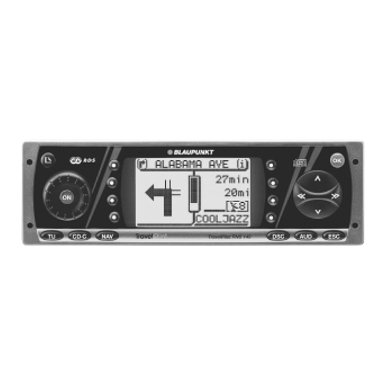
- Page 1 Radio/Navigation TravelPilot RNS 149 US Installation instructions ®...
-
Page 2: Installation Instructions
Installation instructions Information on proper Safety information installation – Faulty installation or servicing of this equipment may result in malfunc- To ensure that the TravelPilot functions tions in the vehicle’s electronic sys- properly, it is essential that the system tems. be calibrated after it has been complete- –... -
Page 3: Fig.2
Installation instructions 1. Installing the antenna 2. Installing the TravelPilot 2.3 Installing the TravelPilot Push all of the plugs into the sockets Connect the antenna wiring to the en- 2.1 Setting the Gyro until they lock into place. Now insert closed bracket (see Fig. -
Page 4: Fig.3
Installation instructions 2.5 Connecting the back-up light 3. Connection diagrams signal wire Power connection to the The back-up light signal wire connects vehicle ISO standard plug ..Fig.1/2 the system to the vehicle back-up light. Power connection to the vehicle-specific plug .... Fig.3 Make sure that this connection is Speaker connection charged with 12 volts when the vehi-... -
Page 5: Fig.5
Installation instructions 4 Ohm 4 Ohm 4 Ohm 4 Ohm Tel.-Mute (ground) Fig.1 Fig.4 GPS antenna Bracket Fig.2 GPS antenna Fig.5 Fig.3 Fig.5 Radio antenna... - Page 6 Installation instructions Fig.6 Fig.6a 90° O.K. Fig.7 90° Fig.8...
- Page 7 Installation instructions 7 10 13 16 19 9 12 15 18 Gala/Speed signal Speaker out RR+ 8 11 14 17 20 — Tel.-Mute (Ground) Speaker out RR- — — Back Up Signal Speaker out RF+ — +12V Battery Speaker out RF- —...
-
Page 8: Installation Instructions
Installation instructions Control cable (Power Antenna +) The control cable is the connected positive output for auxiliary components e.g.: power antennas, (maximum load < 150 mA). Important! Do not connect the control cable to terminal 15 (Plus connected) or terminal 30 (continuous plus). Relais Wheel sensor (required for vehicles without...
Need help?
Do you have a question about the RNS 149 US and is the answer not in the manual?
Questions and answers