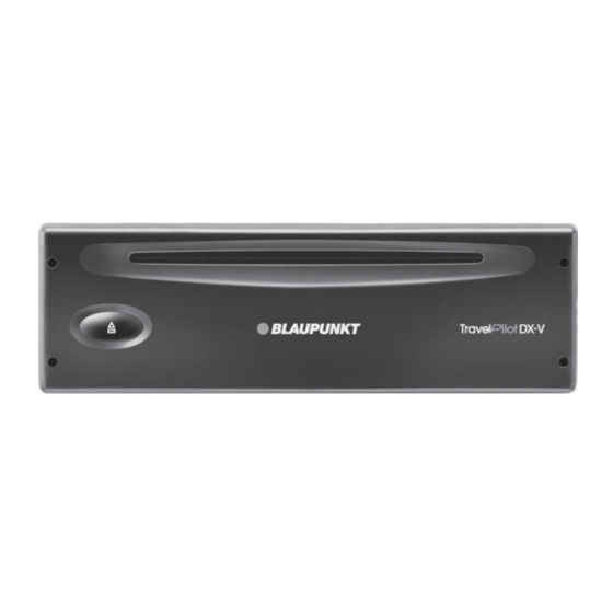
Blaupunkt TravelPilot DX-V Installation Instructions Manual
Hide thumbs
Also See for TravelPilot DX-V:
- Operating instructions manual (75 pages) ,
- Operating instructions manual (78 pages)
Summary of Contents for Blaupunkt TravelPilot DX-V
- Page 1 TravelPilot Navigation TravelPilot DX-V Installation instructions http://www.blaupunkt.com...
-
Page 2: Safety Precautions
Congratulations on your purchase of this Blaupunkt product. Thank you for the trust you are putting into our brand! The following installation instructions are intended to help you getting the best performance from your Blaupunkt product. To avoid the aggravation of costly mistakes and serious damage to your system, please read all of the instructions carefully before you begin. If you’re not confident that you can install the unit correctly, have it installed by a qualified Blaupunkt installation technician. -
Page 3: Table Of Contents
Contents Safety precautions ....2 Installing the control unit ...6 What’s included in the delivery ....10 Installation ......4 Important installation information for the Assembly illustrations ..13 Description .......... 4 speedometer signal ....6 Notes on how the system functions ... 4 Connection diagrams ..14 Installation preparations .... -
Page 4: Installation
Installation preparations Description Before starting the installation, check to see that The TravelPilot DX-V navigation system is an independent sys- no parts from the installation pack are missing..page 10 tem with an integrated gyroscope. After a destination has been... -
Page 5: Installing The Navigation Unit
Connect the switching plus wire (black) to terminal 15 on The TravelPilot DX-V can be installed in the car radio compart- the fuse holder (plus is switched by the ignition) behind the ment in the vehicle (installation depth 218 mm). You will need fuse. -
Page 6: Installing The Display
Installation Installing the display Installing the control unit Safety instructions Mount the control unit bracket in a location where the control unit will be easily accessible, e.g. on the centre console. The display support must never be greased or lubricated Important! with oil. -
Page 7: Connecting The Speedometer Signal
The video input socket is intended for future applications. For We assume no responsibility for any equipment that is in- information on connection options, please contact a Blaupunkt stalled incorrectly and the consequences thereof! dealer or our hotline. See connection diagram for assignment. -
Page 8: System Test After Installation
Proceed as follows: Calibrating the Gala curve 1. Turn off TravelPilot DX-V After the TravelPilot DX-V is calibrated, the values that were 2. Press the button and keep it pressed. determined must be transferred to the control unit software so 3. -
Page 9: Technical Data
Technical data Basic navigation unit Rated voltage (Urat) 14 V / DC Rated current (I) Typically 0.55 A (Imax 1.05 A) Stand-by current Typically 0.35 A Speech output / volume Max. 3 Watt/4 Ohm Time to first position computation (Warm start, memory refresh) <... -
Page 10: What's Included In The Delivery
What’s included in the delivery TravelPilot DX-V 8 672 000 013 GPS-antenna 7 612 001 078 Navigation unit with integrated gyroscope and GPS receiver 7 612 001 073/74 depending on the model 8 601 360 105 Operating unit incl. bracket and IR sensor (eye):... - Page 11 What’s included in the delivery 8 618 842 033 8 618 841 988 4.5 m of back-up lights signal wire 4 m of speedometer wire blue brown yellow white 8 604 492 627 8 604 492 513 Monitor cable 0.3 m of connection wire (compartment C1) (The cable is only included in the scope of delivery when com- bined with the 7 612 001 071/072 monitor.) 8 604 492 514...
- Page 12 What’s included in the delivery 8 606 590 212 Universal equipment housing 8 604 492 522 Tuner box / RC 09H connection wire 8 604 492 573 Y-adapter...
-
Page 13: Assembly Illustrations
Assembly illustrations 8 601 310 555 Fig. 1 Fig. 4 Fig. 2 Fig. 1.1 Fig. 3 Allgemeines Kurzanlei- Zieleingabe Touren Zielspeicher Einstellun- Anhang... -
Page 14: Connection Diagrams
Assembly illustrations Connection diagrams 7 10 13 16 19 9 12 15 18 14 17 20 8 11 90˚ Gala/Tacho – Data Out Data In – – Mute (AR) RFLS – — Permanent +12V – — – Speaker out LF+ Line GND Illumination Speaker out LF-... -
Page 15: Dx-V And Rc 09H In The Front
Connection diagrams Installation location: DX-V and RC 09H in the front (DIN compartment) GPS-antenna TravelPilot DX-V IR remote control RC 09H to the monitor Video-IN TMC car radio connection (Accessory cable Skyline II: 7 607 612 093; not connected Funline II: 7 607 613 093) -
Page 16: Tmc Tuner Box And
Connection diagrams Installation location : DX-V in the car boot TMC tuner box and RC 09H in the front (DIN compartment) to the monitor TravelPilot DX-V Y-adapter 8 604 492 573 Attach the ground cable using the torx-head screw provided... -
Page 17: Dx-V, Tmc Tuner Box And Rc 09H In The Front
Connection diagrams Installation location : DX-V, TMC tuner box and RC 09H in the front (DIN compartment) to the monitor TravelPilot DX-V Attach the ground cable using the torx-head screw provided 8 604 492 540 Tunerbox 8 604 492 534... -
Page 18: Dx-V Connection To Terminal Area A
Connection diagrams DX-V connection to terminal area A TravelPilot DX-V Earth black Illumination Speedometer signal RFLS 1 2 V Back-up lights GPS-antenna signal = +12 V... - Page 19 902-120234 916-467952 Sweden 08-7501500 08-7501810 Switzerland (CH) 01-8471644 01-8471650 Czech. Rep. (CZ) 02-6130 0441 02-6130 0514 Hungary 01-333 9575 01-324 8756 Poland (PL) 0800-118922 022-8771260 Turkey (TR) 0212-3350677 0212-3460040 Blaupunkt GmbH 01/ 2004 CM/PSS 8 622 402 694 B (GB)


Need help?
Do you have a question about the TravelPilot DX-V and is the answer not in the manual?
Questions and answers