Table of Contents
Advertisement
Hollow Chisel
Mortiser
(Model MM300)
PART NO. 906119 - 06-15-02
Copyright © 2002 Delta Machinery
To learn more about DELTA MACHINERY
ESPAÑOL: PÁGINA 19
visit our website at: www.deltamachinery.com.
For Parts, Service, Warranty or other Assistance,
1-800-223-7278 (
1-800-463-3582).
please call
In Canada call
Advertisement
Table of Contents

Subscribe to Our Youtube Channel
Related Manuals for Delta ShopMaster MM300


Summary of Contents for Delta ShopMaster MM300
- Page 1 Hollow Chisel Mortiser (Model MM300) PART NO. 906119 - 06-15-02 Copyright © 2002 Delta Machinery To learn more about DELTA MACHINERY ESPAÑOL: PÁGINA 19 visit our website at: www.deltamachinery.com. For Parts, Service, Warranty or other Assistance, 1-800-223-7278 ( 1-800-463-3582). please call...
-
Page 2: General Safety Rules
If you have any questions relative to a particular application, DO NOT use the machine until you have first contacted Delta to determine if it can or should be performed on the product. - Page 3 (tools, scrap pieces, etc.). 19. THE USE of attachments and accessories not 6. ALWAYS keep hands, fingers and hair away from recommended by Delta may result in the risk of injuries. the rotating bit. 20. TURN THE MACHINE “OFF” AND DISCONNECT 7.
-
Page 4: Motor Specifications
POWER CONNECTIONS A separate electrical circuit should be used for your machines. This circuit should not be less than #12 wire and should be protected with a 20 Amp time lag fuse. If an extension cord is used, use only 3-wire extension cords which have 3- prong grounding type plugs and matching receptacle which will accept the machine’s plug. -
Page 5: Extension Cords
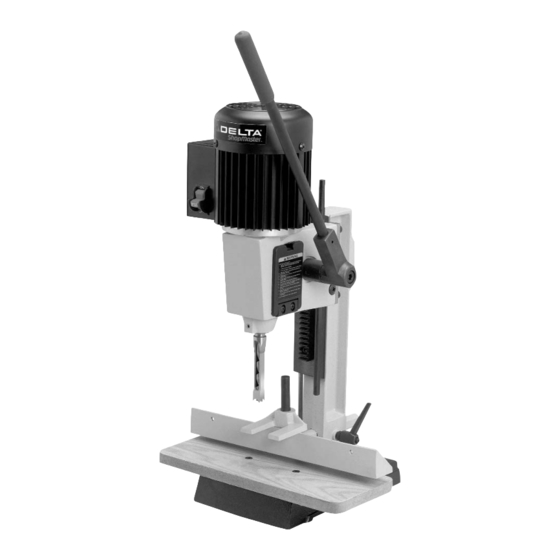
Delta ShopMaster Model MM300 is easier to operate than a conventional drill press equipped with a mortising attachment. The model MM300 is made of cast-iron and steel for rigidity and stability. The motriser comes with a standard 3-jaw type key chuck for positive gripping of mortising bits. - Page 6 HOLLOW CHISEL MORTISER PARTS Fig. 2 A - Mortising Machine M - M6x1x35mm Flat Head Screws (2) (for assembling table to base) B - Chuck Key N - M6x1x25mm Pan Head Screws (2) (for assembling C - Wrench tool and chisel holder) D - Tool and Chisel Holder O - Spring (for raising and lowering handle) E - Hydraulic Cylinder...
-
Page 7: Hydraulic Cylinder
ASSEMBLY WARNING: FOR YOUR OWN SAFETY, DO NOT CONNECT THE MACHINE TO THE POWER SOURCE UNTIL THE MACHINE IS COMPLETELY ASSEMBLED AND YOU READ AND UNDERSTAND THE ENTIRE INSTRUCTION MANUAL. RAISING AND LOWERING HANDLE 1. Assemble hub of handle assembly (A) Fig. 3, to end of pinion shaft (B) and fasten handle to pinion shaft using special screw (C) and spring (D). - Page 8 TABLE 1. Assemble the table (A) Fig. 7, to the base using the two M6x1x35mm flat head screws (B) and T-nuts (C). Insert the two screws (B) into the two holes (D) in table (A). Place the two T-nuts (C) into the slots (E) provided in the bottom of the base and tighten the two screws (B) into the two T-nuts (C) securely.
-
Page 9: Tool And Chisel Holder
5. Insert bar of fence assembly (E) Fig. 11, through hole in column as shown. Tighten handle (C) against flat on fence bar to hold fence in position. NOTE: Handle (C) is spring-loaded and can be repositioned on the stud located underneath the handle by pulling out the handle and repositioning it on the stud. - Page 10 FASTENING MACHINE TO SUPPORTING SURFACE If during operation there is any tendency for the mortiser to tip over, slide or walk on the supporting surface, the base must be secured to the supporting surface with fasteners (not supplied), through the two holes (A) Fig. 16, located in the mortiser base.
- Page 11 4. Push bit (A) Fig. 23, up through chisel and into chuck (G) as far as it will go, and lock bit in chuck using chuck key supplied. Fig. 23 5. Loosen set screw (D) Fig. 24, and push chisel (B) up against bottom of bushing (E), as shown, and tighten set screw (D).
-
Page 12: Operating Controls And Adjustments
OPERATING CONTROLS AND ADJUSTMENTS ON-OFF SWITCH The switch (A) Fig. 26, is located on the side of the motor. To turn the machine “ON”, move the switch (A), up to the “ON” position. To turn the machine “OFF”, move the switch down to the “OFF” position. Fig. -
Page 13: Chisel Parallel To Workpiece
DEPTH STOP ROD A depth stop rod (A) Fig. 29, is provided to limit the depth of the chisel (B). To adjust the depth stop rod (A), loosen screw (C) and lower head until the chisel (B) is at the desired depth. Lower depth stop rod (A) until it contacts base (D) and tighten screw (C). - Page 14 SLIDING FIT BETWEEN HEAD AND COLUMN A dovetail gib (A) Fig. 32, is provided on the rear of the head to insure a good sliding fit between the head and the column when the head is raised and lowered. Adjustment is made by loosening the two screws (B) and turning adjusting screws (C).
- Page 15 USING AUXILIARY WOOD FENCE When mortising extra high workpieces (A) Fig. 35, an auxiliary fence (B) can be fastened to the fence (C) with wood screws (D) through the two holes in the fence. This provides additional support for the workpiece during the mortising operation.
- Page 16 USING BITS WITH EXTRA LONG SHANKS When using bits with extra long shanks, it will be necessary to remove the extension (A) Fig. 37. This can be accomplished by inserting screwdriver into center hole Fig. 37 of motor end cap (B) Fig. 38, and into slot in end of armature shaft.
- Page 17 NOTES...
-
Page 18: Parts, Service Or Warranty Assistance
Two Year Limited Warranty Delta will repair or replace, at its expense and at its option, any Delta machine, machine part, or machine accessory which in normal use has proven to be defective in workmanship or material, provided that the customer returns the product prepaid to a Delta factory service center or authorized service station with proof of purchase of the product within two years and provides Delta with reasonable opportunity to verify the alleged defect by inspection.
Need help?
Do you have a question about the ShopMaster MM300 and is the answer not in the manual?
Questions and answers