Table of Contents
Advertisement
Quick Links
Download this manual
See also:
Online Manual
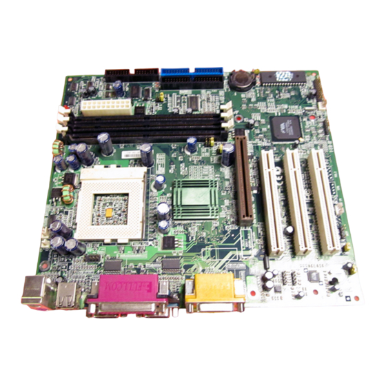
Modem-CN
JP12 Onboard Sound
CD-IN
AUX-IN
4X AGP Expansion Slot
Front Audio Connector
WOM
Wake on Modem
WOL
Wake on LAN
USB2 Connector
2Mbit Flash ROM
Multilanguage BIOS
Virus Protection
Wake On RTC Timer
IrDA Connector
Housing Fan
Front Panel Connector
JP14 Clear CMOS
Battery-less &
long-life Design
PS/2 Mouse
Connector
PS/2 Keyboard
Connector
FDD Connector
ATA/66 IDE Connector
Suspend to HDD
(ATA/100 for optional)
SPP/EPP/ECP Parallel Port
USB Port
COM 2 Port
COM 1 Port
PC99 Back Panel
Resettable Fuse
CPU Fan Connector
System Voltage & Fan Monitoring
Buzzer
Socket370 CPU with Voltage and
Frequency Auto-detection
supports Intel
300MHz~1GHz+ CPU
CPU Jumper-less Design
Over-current Protection
Thermal Protection
VIA 694X Chipset
Support 133MHz FSB Clock
168-pin DIMM Socket x3
supports PC100/133 SDRAM up to 1.5GB
ATX Power Connector
AC Power Auto Recovery
JP23/JP29
FSB/PCI Clock Ratio
MIDI/Game Port
MIC-In
Line-In
Speaker Out
®
®
Pentium
III & Celeron™
Advertisement
Table of Contents

Related Manuals for AOpen MX34


Summary of Contents for AOpen MX34
- Page 1 SPP/EPP/ECP Parallel Port PS/2 Mouse MIDI/Game Port Connector USB Port PS/2 Keyboard COM 2 Port COM 1 Port Connector Modem-CN MIC-In PC99 Back Panel JP12 Onboard Sound Line-In Speaker Out Resettable Fuse CD-IN CPU Fan Connector AUX-IN System Voltage & Fan Monitoring 4X AGP Expansion Slot Buzzer Front Audio Connector...
-
Page 2: Jp14 Clear Cmos
CODEC chip. If you select Disable, you can use your preferred PCI sound card. 80-Wire IDE Cable x 1 Floppy Drive Cable x 1 Bonus Pack CD disc x 1 This Easy Installation Guide x 1 Enable Disable PART NO.: 49.88502.007 DOC. NO.: MX34-EG-E0103D... -
Page 3: Jp29/Jp23 Fsb/Pci Clock Ratio
3. Installing CPU and Fan 4. JP29/JP23 FSB/PCI Clock Ratio Plug CPU to Socket370 connector. Be careful of This jumper is used to specify the relationship of PCI and FSB clock. Generally speaking, CPU orientation. Plug in the fan cable to the 3-pin we suggest you do not change the default setting. -
Page 4: Connecting Front Panel Cable
5. Connecting Front Panel Cable 7. Configuring System Memory This motherboard has three 168pin DIMM sockets that allow you to install system memory up to 1.5GB. SDRAM, VCM SDRAM, Registered Keylock SPWR SDRAM are supported. ACPI & IDE LED Power LED Tip: The driving capability of new generation chipset is limited due to the lack of a memory buffer Speaker... -
Page 5: Front Audio
11. Support 2 USB Port 9. Connecting ATX Power Connector This motherboard supports four USB ports. Two of them are on back panel connector, The ATX power supply uses 20-pin connector shown below. Make sure you plug in the other two are on the left-bottom area of this motherboard. With proper cable, you the right direction. -
Page 6: Bios Upgrade
14. AOpen Bonus Pack CD 16. BIOS Upgrade AOpen Easy Flash is more user-friendly than traditional flash method. The BIOS binary You can use the autorun menu of Bonus CD disc. Choose the utility and driver and file and flash routine are combined together and you simply run a single file to complete select model name. -
Page 7: Part Number And Serial Number
Turn off the system and re-connect the IDE cable.Check The problem should be caused by the if the system can reboot successfully. IDE cables or HDD itself. Re-install Windows 95, Windows 98 or Windows NT. MX34 is model name of motherboard, R1.00 is BIOS version. - Page 8 Dear Customer, Test Report: We recommend to choose board/card/device from the Thanks for choosing AOpen products. To provide the best and fastest service to compatibility test reports for assembling your PC. our customer is our first priority. However, we receive numerous emails and http://www.aopen.com.tw/tech/report/default.htm...
Need help?
Do you have a question about the MX34 and is the answer not in the manual?
Questions and answers