Table of Contents
Advertisement
Quick Links
Advertisement
Table of Contents

Related Manuals for AOpen MX3W-V


Summary of Contents for AOpen MX3W-V
- Page 1 MX3W-V User's Guide Printed in Taiwan PART NO.: DOC. NO.: MX3WV-1-E9910A...
-
Page 2: Award Bios
AWARD BIOS MX3W-V Motherboard User's Guide Document Number : MX3WV-1-E9910A Model and revision : For MX3W-V rev 1.xx Manual version : English, rev A Release Date : Oct. 8, 1999 More help for latest information: Taiwan http://www.aopen.com.tw http://www.aopenusa.com Europe http://www.aopen.nl... - Page 3 AWARD BIOS Copyright Copyright 1999 by this company. All rights reserved. No part of this publication may be reproduced, transmitted, transcribed, stored in a retrieval system, or translated into any language or computer language, in any form or by any means, electronic, mechanical, magnetic, optical, manual or otherwise, without the prior written permission of this company.
- Page 4 AWARD BIOS Disclaimer This company makes no representations or warranties, either expressed or implied, with respect to the contents hereof and specifically disclaims any warranties, merchantability or fitness for any particular purpose. Any software described in this manual is sold or licensed "as is". Should the programs prove defective following their purchase, the buyer (and not this company, its distributor, or its dealer) assumes the entire cost of all necessary servicing, repair, and any incidental or consequential damages resulting from any defect...
-
Page 5: Declaration Of Conformity
AWARD BIOS FCC Class B Radio Frequency Declaration of Conformity This equipment has been tested and found to comply with the limits for a Class B Subassembly -CPU Board device, pursuant to Part 15 of FCC Rules. Operation is subject to the following two conditions: 1. - Page 6 AWARD BIOS Organization Chapter 1, Overview, covers the introduction and specifications of the system board and special features. Chapter 2, Hardware Installation, describes hardware jumpers, connectors and memory configuration. There are user friendly drawings to locate jumper and connector. Chapter 3, AWARD BIOS, explains the system BIOS and tells how to configure the system by setting the BIOS parameters.
- Page 7 AWARD BIOS Conventions The following conventions are used in this manual: Text entered user, Represent text input by the user, default settings, default settings and recommended recommended selections selections <Enter>, <Tab>,<Ctl>, <Alt>, Represent the actual keys that you <Ins>, <Del>, etc have to press on the keyboard.
-
Page 8: Table Of Contents
AWARD BIOS Contents chapter 1 overview 1.1 Specifications...............4 1.2 APM Suspend to Hard Drive ........5 1.3 Zero Voltage Wake On Modem ........8 1.4 System Voltage Monitoring ........10 1.5 Fan Monitoring ............10 1.6 CPU Thermal Protection ..........11 1.7 Battery-less Design ............11 chapter 2 Hardware Installation........ - Page 9 AWARD BIOS 2.3.11 Panel Connector..........11 2.3.12 IrDA Connector...........12 2.3.13 Wake On Modem Connector ......13 2.3.14 Wake On LAN Connector ........13 2.3.15 CD Audio Connector...........14 2.3.16 Mono In/Mic Out Connector ........14 2.4 Configuring the System Memory.......15 2.5 Onboard Audio............18 2.5.1 Setting Up in Windows 95/98........20 2.5.2 Setting Up in NT4.0 ..........21 chapter 3 Award BIOS ............
-
Page 10: Chapter 1 Overview
IDE, PCI 2.2 and USB port. It has two Dual in-line Memory Module (DIMM) slots that allow to install PC100 SDRAMs and expand up to a maximum of 512MB. Also, MX3W-V uses 4M bit Flash ROM BIOS to reserve for future new functions. - Page 11 AWARD BIOS ACPI Suspend to Hard Drive The conventional "Suspend to Hard Drive" function is a private design of AOpen motherboards, the requirement to run it is a BIOS revision and correct chipset that supports this function. However, nowadays "Suspend to Hard Drive" has been become widely known as the "S4 - Hibernation"...
- Page 12 Resetable Fuse This motherboard implements resetable fuses to prevent any accidental short circuit caused by keyboard or USB devices hot plug. FCC DoC certificate MX3W-V has passed FCC DoC test. The radiation is very low, you can use any kind of housing.
- Page 13 AWARD BIOS Note: This motherboard is battery-less, that means the RTC (real time clock) can keep running without battery as long as the power cord is plugged. But in case of power failure or the power cord unplugged, you need to reset date and time from "Standard CMOS Setup"...
-
Page 14: Specifications
AWARD BIOS Specifications Form Factor Micro ATX Board Size 244 mm x 220 mm Celeron PPGA 168-pin DIMM x2, maximum 512 PC100 SDRAM. System Memory Intel 810 AGPset Chipset Intel I752 Onboard AGP Audio CODEC AD1881 Expansion Slots PCI x3 and AMR x1 Serial Port Two serial ports UART 16C550 compatible, and the 3rd UART for IR function. -
Page 15: Acpi Suspend To Hard Drive
ACPI Suspend to Hard Drive For a detailed installation procedure please refer to the following procedure to enable ACPI Suspend to Hard Drive on the AOpen MX3W-V motherboard. First please check if your system meets the following requirements, then follow the procedure step by step. - Page 16 AWARD BIOS 5. You've already implemented ACPI with Suspend-to-Harddisk. Click "Start - > Shut Down -> Standby" then the screen will go off immediately. And 1 minute or so will be taken for the system to save what's in the memory to the harddrive;...
- Page 17 AWARD BIOS b. Right click and select Modify, change "01" to "00" to make it "0000 02". <Note> "02" means Windows 98 is ACPI acknowledged but disable ACPI function. c. Save changes. 2. Select "Add New Hardware" under Control Panel. Allow Windows 98 to detect new hardware.
- Page 18 AWARD BIOS ACPI Suspend to DRAM This motherboard supports ACPI Suspend to DRAM function. With this function, you can resume your original work directly from DRAM without going through the Win98 booting process and run your application again. Suspend to DRAM saves your current work into the system memory. To implement ACPI Suspend to DRAM, please follow the procedures as below.
- Page 19 AWARD BIOS Wake On Keyboard/Mouse This function allows you to power on your system by clicking a hot key or a mouse button that you specified. Besides, you can also disable the function of the power button and only the preset keys (like a password) can boot your system.
- Page 20 AWARD BIOS Caution: To implement this function, the 5V Stand By current of ATX power supply must be greater than 800mA. Caution: Wake On Mouse function applies to PS/2 mouse only Caution: The mouse can’ t be moved between double clicking. Caution: If you set a Password but forget it, please clear CMOS.
-
Page 21: Zero Voltage Wake On Modem
0V Wake On Modem, but if you use external modem, you have to keep the box modem always power-on. AOpen MX3W-V and internal modem card implement special circuit (patent applied) and make sure the modem card works properly without any power. - Page 22 AWARD BIOS For Internal Modem Card (AOpen FM56-P): 1. Go into BIOS setup, Power Management ? 0V Wake On Modem, select Enabled. 2. Setup your application, put into Windows 95. 3. Turn system power off by soft power switch. 4. Connect 4-pin Modem Ring-On cable from FM56-P RING connector to MX3W-V connector WKUP.
-
Page 23: System Voltage Monitoring
AWARD BIOS System Voltage Monitoring This motherboard implements a voltage monitoring system. As you turn on your system, this smart design will continue to monitor your system’ s working voltage. If any of the system’ s voltage is over the component's standard there will be an alarm through application software such as the Hardware Monitoring Utility to warn the user. -
Page 24: Cpu Thermal Protection
Setup and system configuration can be restored from EEPROM, only the system clock needed to be re-set to current date/time. For the convenience of end user, MX3W-V still shipped with one Lithium (CR- 2032) battery. If you prefer to use battery, you can still insert it into battery... -
Page 25: Chapter 2 Hardware Installation
AWARD BIOS Chapter 2 Hardware Installation This chapter gives you a step-by-step procedure on how to install your system. Follow each section accordingly. Caution: Electrostatic discharge (ESD) can damage your processor, disk drives, expansion boards, and other components. Always observe the following precautions before you install a system component. -
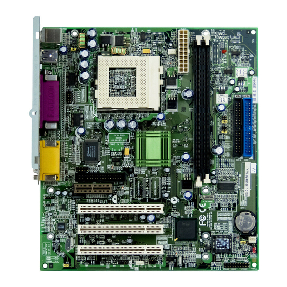
Page 26: Jumper And Connector Locations
AWARD BIOS 2.1 Jumper and Connector Locations The following figure shows the locations of the jumpers and connectors on the system board: CD-IN MODEM-CN COM1 PRINTER JP12 PS/2 MS COM2 JP28 IrDA SB-Link CPUFAN1 DIMM1 DIMM2 JP27 IDE2 JP14 PANEL IDE1 FAN1... - Page 27 AWARD BIOS Jumpers: JP12: Enable/Disable Onboard Audio JP14: Clear CMOS JP27: SPK Out JP28: Enable/Disable KB/MS Wake Up Connectors: PS2: PS/2 mouse connector PS/2 keyboard connector COM1: COM1 connector COM2: COM2 connector PRINTER: Printer connector PWR2: ATX power connector USB: USB connector FDC: Floppy drive connector...
-
Page 28: Jumpers
AWARD BIOS 2.2 Jumpers With the help of Celeron PPGA VID signal and SMbus, this motherboard is jumper-less design. 2.2.1 Selecting the CPU Frequency Celeron PPGA VID signal and SMbus clock generator provide CPU voltage auto-detection and allow user to set CPU frequency through CMOS setup, no jumper or switch is needed. - Page 29 AWARD BIOS Warning: INTEL 810 chipset supports a maximum of 100MHz CPU FSB, the higher clock settings are for internal test only. These settings exceed the specification of the chipset, which may cause serious system damage.
-
Page 30: Setting The Cpu Voltage
AWARD BIOS 2.2.2 Setting the CPU Voltage This motherboard supports Celeron PPGA VID function, the CPU core voltage is automatically detected, the range is from 1.3V to 2.05V. 2.2.3 Clearing the CMOS JP14 Clear CMOS You need to clear the CMOS if you forget your system password. -
Page 31: Onboard Audio
AWARD BIOS Tip: If your system hangs or fails to boot because of over- clocking, please clear CMOS and the system will go back to the default setting (233MHz or 350MHz). Tip: If your system hangs or fails to boot because of over- clocking, simply use <Home>... - Page 32 AWARD BIOS JP28 JP28 Disabled Enabled 2.2.6 SPK Out JP27 SPK Out This jumper is used to enable or disable speaker out. Disabled Enabled JP27 JP27 Disabled Enabled...
-
Page 33: Connectors
AWARD BIOS 2.3 Connectors 2.3.1 Power Cable The ATX power supply uses 20-pin connector shown below. Make sure you plug in the right direction. Caution: Make sure that the power supply is off before connecting or disconnecting the power cable. 3.3V 5V SB 3.3V... -
Page 34: Ps/2 Mouse
AWARD BIOS 2.3.3 PS/2 Mouse The onboard PS/2 mouse connector is a 6-pin Mini-Din connector marked PS2. The view angle of drawing shown here is from back panel of the housing. PS/2 Mouse 2.3.4 Keyboard The onboard PS/2 keyboard connector is a 6-pin Mini-Din connector marked KB2. -
Page 35: Serial Devices (Com1/Com2)
AWARD BIOS 2.3.5 Serial Devices (COM1) The onboard serial connectors COM1 are 9-pin D-type connector on the back panel of mainboard. COM1 2.3.6 Serial Devices (COM2) Plug in the IDE cable to the COM2 connectors. COM2 2-11... -
Page 36: Printer
AWARD BIOS 2.3.7 Printer The onboard printer connector is a 25-pin D-type connector marked PRINTER. The view angle of drawing shown here is from back panel of the housing. PRINTER 2.3.8 USB Device You can attach USB devices to the USB connector. The motherboard contains two USB connectors, which are marked as USB. -
Page 37: Floppy Drive
AWARD BIOS 2.3.9 Floppy Drive Connect the 34-pin floppy drive cable to the floppy drive connector marked as FDC on the system board. 2.3.10 IDE Hard Disk and CD ROM This mainboard supports two 40 pin IDE connectors marked as IDE1 and IDE2. -
Page 38: Panel Connector
AWARD BIOS IDE2 IDE1 Caution: The specification of IDE cable is maximum 46cm (18 inches), make sure your cable does not excess this length. Caution: For better signal quality, it is recommended to set far end side device to master mode and follow the suggested sequence to install your new device. -
Page 39: Irda Connector
AWARD BIOS The Panel (multifunction) connector is a 20-pin connector marked as SPWR PANEL on the board. Attach the KEYLOCK power LED, keylock, speaker, SPWR, ACPI & POWER LED IDE LED and reset switch to the IDE LED corresponding pins as shown in the IDE LED figure. - Page 40 AWARD BIOS Description Install infrared module onto IrDA connector and enable infrared function FIRRX (FAST IR) from BIOS setup, make sure to have correct orientation when you plug onto CIRRX (Consumer IR) IrDA connector. IRRX (STANDARD IR) 5VSB IRTX (STANDARD IR) IrDA 2-16...
-
Page 41: Wake On Modem Connector
Internal Modem card consumes no power when system RING power is off, it is recommended to use Internal Modem. To use AOpen MP56, connect 4-pin cable from RING connector of MP56 to WOM connector on the mainboard. 2.3.14 Wake On LAN Connector Description This mainboard implements a WOL connector. -
Page 42: Cd Audio Connector
AWARD BIOS 2.3.15 Sound Blaster LINK Description SB-LINK is used to connect Creative PCI sound GNT# card. If you have a Creative PCI sound card installed, it is necessary to link the card to this connector for compatibility issue under DOS environment. -
Page 43: Mono In/Mic Out Connector
AWARD BIOS 2.3.16 Mono In/Mic Out Connector Description This connector is used to connect Mono In/Mic Out Mono In connector of an internal modem card. The pin 1-2 is Mono In, and the pin 3-4 is Mic Out. Please note that there is no standard for this kind of connector yet, only some internal modem cards Mic Out implement this connector. -
Page 44: Audio Connector
AWARD BIOS 2.3.18 Audio Connector This motherboard comes with a 16-bit audio CODEC (AD1881) onboard. Game Port LINE-IN To fully utilize the audio functions, you may connect various peripheral devices that the audio chip supports. The following figure shows the different devices that you can connect. -
Page 45: Configuring The System Memory
AWARD BIOS 2.4 Configuring the System Memory The DIMM type supported is PC100 SDRAM (Synchronous DRAM) only. This motherboard has two 168-pin DIMM (Dual-in-line Memory Module) sockets that allow you to install system memory up to 512MB. Pin1 DIMM modules can be identified by the following factors: I. - Page 46 AWARD BIOS III. Buffered and non-buffered: This motherboard supports non-buffered DIMMs. You can identify non-buffered DIMMs and buffered DIMMs according to the position of the notch, following figure is for your reference: non-buffered Reserved buffered Because the positions are different, only non-buffered DIMMs can be inserted into the DIMM sockets on this motherboard.
- Page 47 AWARD BIOS The following table lists the recommended DRAM combinations of DIMM: DIMM Bit size Single/ Chip DIMM size Recommended Data chip per side Double side count 1M by 16 1Mx64 1M by 16 1Mx64 16MB 2M by 8 2Mx64 16MB 2M by 8 2Mx64...
-
Page 48: Chapter 3 Award Bios
AWARD BIOS Chapter 3 Award BIOS This chapter tells how to configure the system parameters. You may update your BIOS via AWARD Flash Utility. Important: Because the BIOS code is the most often changed part of the mainboard design, the BIOS information contained in this chapter (especially the Chipset Setup parameters) may be a little different compared to the actual BIOS that... -
Page 49: Entering The Award Bios Setup Menu
AWARD BIOS Entering the Award BIOS Setup Menu The BIOS setup utility is a segment of codes/routines residing in the BIOS Flash ROM. This routine allows you to configure the system parameters and save the configuration into the 128 byte CMOS area, (normally in the RTC chip or directly in the main chipset). -
Page 50: Standard Cmos Setup
AWARD BIOS Standard CMOS Setup The "Standard CMOS Setup" sets the basic system parameters such as the date, time, and the hard disk type. Use the arrow keys to highlight an item to select the value for each item. Standard CMOS ? Date To set the date, highlight the Date parameter. - Page 51 AWARD BIOS Tip: For an IDE hard disk, we recommend that you use the "IDE HDD Auto Detection" to enter the drive specifications automatically. See the section "IDE HDD Auto Detection". Standard CMOS ? Drive A Standard CMOS ? Drive B These items select floppy drive type.
-
Page 52: Advanced Bios Features
AWARD BIOS Advanced BIOS Features This screen appears when you select the option "BIOS Features Setup" from the main menu. Advanced BIOS Features ? Virus Warning Set this parameter to Enabled to activate the warning Virus Warning message. This feature protects the boot sector and Enabled partition table of your hard disk from virus intrusion. - Page 53 AWARD BIOS CPU L2 Cache This item lets you enable or disable L2 Cache ECC checking. Enabled Disabled Advanced BIOS Features ? Quick Power On Self Test Quick Power on This parameter speeds up POST by skipping some items that are normally checked. Self test Enable Disabled...
- Page 54 AWARD BIOS Advanced BIOS Features ? Third Boot Device Third Boot Device This parameter allows you to specify the system boot up search sequence. The hard disk ID are listed below: LS/ZIP C: Primary master D: Primary slave SCSI E: Secondary master CDROM F: Secondary slave LS: LS120...
- Page 55 AWARD BIOS Typematic Rate Set this parameter to Enable/Disable the keyboard Setting repeat function. When enabled, continually holding down a key on the keyboard will generate repeatedly Enabled keystrokes. Disabled Advanced BIOS Features ? Typematic Rate (Chars/Sec) Typematic Rate This item allows you to control the speed of repeated keystrokes.
- Page 56 AWARD BIOS OS Select for Set to OS/2 if your system is utilizing an OS/2 DRAM > 64MB operating system and has a memory size of more than 64 MB. OS/2 Non-OS/2...
-
Page 57: Advanced Chipset Features
AWARD BIOS Advanced Chipset Features The "Chipset Features Setup" includes settings for the chipset dependent features. These features are related to system performance. Caution: Make sure you fully understand the items contained in this menu before you try to change anything. You may change the parameter settings improve... - Page 58 AWARD BIOS Advanced Chipset Features ? SDRAM RAS Precharge Time SDRAM RAS The RAS Precharge means the timing to inactive Precharge Time RAS and the timing for DRAM to do precharge before next RAS can be issued. RAS is the address latch control signal of DRAM row address.
- Page 59 AWARD BIOS On-Chip Video This item is used to enable or disable the onchip AGP. Enabled Disabled Advanced Chipset Features ? On-Chip Video Window Size On-Chip Video This item is used to select graphic display cache Window Size window size. 64MB 32MB Advanced Chipset Features ? Cas# Latency...
- Page 60 AWARD BIOS RAS# Precharge This item will affect SDRAM performance. If the system fails to bootup, please set this item to Slow Slow. Fast 3-13...
- Page 61 AWARD BIOS Integrated Peripherals This submenu appears if you select the option "Integrated Peripherals" from the main menu. This option allows you to configure the I/O features. Integrated Peripherals ? On-Chip Primary PCI IDE Integrated Peripherals ? On-Chip Secondary PCI IDE On-Chip Primary This parameter lets you enable or disable the IDE PCI IDE...
- Page 62 AWARD BIOS Integrated Peripherals ? IDE Primary Master UDMA Integrated Peripherals ? IDE Primary Slave UDMA Integrated Peripherals ? IDE Secondary Master UDMA Integrated Peripherals ? IDE Secondary Slave UDMA IDE Primary Master This item allows you to set the Ultra DMA/33 mode UDMA supported by the hard disk drive connected to your primary IDE connector.
-
Page 63: Onboard Audio
AWARD BIOS Caution: You can not use both USB driver and USB legacy keyboard at the same time. Disable "USB Legacy Support" if you have USB driver in the operating system. Integrated Peripherals ? Init Display First Init Display First If you installed a PCI VGA card, this item lets you decide which one is the initial display card. - Page 64 AWARD BIOS Power On Function This item used select Wake Keyboard/Mouse mode. Any Key Any Key: This function allows you wake up the Button Only system by clicking any key. Keyboard 98 Button Only: Disable Wake on KB/MS function. Password You can boot up your system by power button only.
- Page 65 AWARD BIOS Hot Key Power On If you select “ Hot Key” option in “ Power On Function” Item, you need to specify a hot key here. Ctrl-F1 Ctrl-F2 Ctrl-F3 Ctrl-F4 Ctrl-F5 Ctrl-F6 Ctrl-F7 Ctrl-F8 Ctrl-F9 Ctrl-F10 Ctrl-F11 Ctrl-F12 Integrated Peripherals ? Onboard FDC Controller Onboard FDC Setting this parameter to Enabled allows you to Controller...
- Page 66 AWARD BIOS Integrated Peripherals ? UART Mode Select This item is configurable only if the "Onboard UART UART Mode Select 2" is enabled. This allows you to specify the mode IrDA of serial port2. The available mode selections are: ASKIR Normal ASKIR Select this setting if you installed an Infrared module via...
- Page 67 AWARD BIOS Integrated Peripherals ? Onboard Parallel Port Onboard Parallel This item controls the onboard parallel port address Port and interrupt. 3BC/IRQ7 378/IRQ7 278/IRQ5 Disabled Note: If you are using an I/O card with a parallel port, make sure that the addresses and IRQ do not conflict.
- Page 68 AWARD BIOS Power Management ? PWRON After PWR-Fail PWRON After PWR- A traditional ATX system should remain at power off Fail stage when AC power resumes from power failure. This design is inconvenient for a network server or Former-Sts workstation, without an UPS, that needs to keep power-on.
-
Page 69: Power Management Setup
AWARD BIOS Power Management Setup The Power Management Setup screen enables you to control the mainboard green features. Power Management ? ACPI Function ACPI Function If your OS is ACPI enabled you have to set this item to Enabled, or there may be unexpected errors. If Enabled your OS is APM mode, you can remain the Disabled Disabled... - Page 70 AWARD BIOS Power Management ? Video Off In Suspend Video Off In Suspend The item is used to decide whether the video is off in the suspend mode. Power Management ? Suspend Type Suspend Type You can select suspend mode by this item. If PWRON Suspend is selected, the CPU will enter PWRON Suspend into Doze mode.
- Page 71 AWARD BIOS Suspend Mode This item lets you set the period of time after which the system enters into Suspend mode. The Suspend Disabled mode can be Power On Suspend or Suspend to 1 Min Hard Drive, selected by "Suspend Mode Option". 2 Min 4 Min 8 Min...
- Page 72 AWARD BIOS Power Management ? CPU THRM-Throttling CPU THRM- Clock Throttling means at the Doze/Standby state, the Throttling CPU clock count in a given time (not the frequency) is reduced to the ratio specified in this parameter. Actually, 87.5% the period per CPU clock is not changed. For example, a 75.0% 66MHz CPU clock remains the same 30ns clock period 62.5%...
- Page 73 AWARD BIOS Time (hh:mm:ss) This item is displayed when you enable the Wake ON RTC Timer option. Here you can specify what hh:mm:ss time you want to wake up the system. Power Management ? Primary IDE 0 Power Management ? Primary IDE 1 Power Management ? Secondary IDE 0 Power Management ? Secondary IDE 1 Power Management ? FDD, COM, LPT Port...
- Page 74 AWARD BIOS PNP/PCI Configurations The PNP/PCI Configuration Setup allows you to configure the ISA and PCI devices installed in your system. This submenu appears if you select the option "PNP/PCI Configurations" from the main menu. PNP/PCI Configuration ? Reset Configuration Data Reset Configuration In case conflict occurs after you assign the IRQs or Data...
- Page 75 AWARD BIOS IRQ 3 If your ISA card is not PnP compatible and requires a special IRQ to support its function, set the selected Legacy ISA IRQ to Legacy ISA. This setting informs the PnP PCI/ISA PnP BIOS to reserve the selected IRQ for the installed legacy ISA card.
-
Page 76: Pc Health Status
AWARD BIOS PC Health Status The PNP/PCI Configuration Setup allows you to configure the ISA and PCI devices installed in your system. This submenu appears if you select the option "PNP/PCI Configurations" from the main menu. PC Health Status ? CPU Warning Temperature CPU Warning This item is used to specify a CPU warning Temperature... - Page 77 AWARD BIOS Frequency/Voltage Control The PNP/PCI Configuration Setup allows you to configure the ISA and PCI devices installed in your system. This submenu appears if you select the option "PNP/PCI Configurations" from the main menu. Frequency/Voltage Control ? Clock Spread Spectrum Clock Spread This item is used to set clock spread spectrum for Spectrum...
-
Page 78: Load Setup Defaults
AWARD BIOS 3.10 Load Setup Defaults The "Load Setup Defaults" option loads optimized settings for optimum system performance. Optimal settings are relatively safer than the Turbo settings. All the product verification, compatibility/reliability test report and manufacture quality control are based on "Load Setup Defaults". We recommend that you use this settings for normal operation. -
Page 79: Save & Exit Setup
AWARD BIOS 3.12 Set Password Password prevents unauthorized use of your computer. If you set a password, the system prompts for the correct password before boot or access to Setup. To set a password: At the prompt, type your password. Your password can be up to 8 alphanumeric characters. -
Page 80: Save Eeprom Defaults
EEPROM Default " to reload. 3.17 How to Upgrade the BIOS AOpen Easy Flash is more user friendly than traditional flash method. The BIOS binary file and flash routine are combined together and you simply run a single file to complete the flash process.
Need help?
Do you have a question about the MX3W-V and is the answer not in the manual?
Questions and answers