Table of Contents
Advertisement
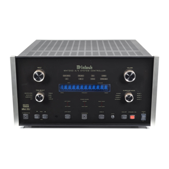
A/V System Controller
MHT200
Owner's Manual
Manufactured under license from Dolby Laboratories. "Dolby", "Pro Logic" and the double-D symbol are trademarks of Dolby Laboratories.
"DTS" and "DTS Digital Surround" are registered trademarks of Digital Theater Systems, Inc.
McIntosh Laboratory, Inc.
2 Chambers Street
Binghamton, New York 13903-2699
Phone: 607-723-3512
FAX: 607-724-0549
Advertisement
Chapters
Table of Contents

Related Manuals for McIntosh MHT200


Summary of Contents for McIntosh MHT200
- Page 1 Manufactured under license from Dolby Laboratories. “Dolby”, “Pro Logic” and the double-D symbol are trademarks of Dolby Laboratories. “DTS” and “DTS Digital Surround” are registered trademarks of Digital Theater Systems, Inc. McIntosh Laboratory, Inc. 2 Chambers Street Binghamton, New York 13903-2699...
-
Page 2: Safety Instructions
The lightning flash with arrowhead, The exclamation point within an equi- within an equilateral triangle, is intended lateral triangle is intended to alert the to alert the user to the presence of user to the presence of important uninsulated “dangerous voltage” within operating and maintenance (servic- the product’s enclosure that may be of ing) instructions in the literature ac-... -
Page 3: Thank You
Fax: 607-723-3636 trode is used. Customer Service If it is determined that your McIntosh product is in need of repair, you can return it to your Dealer. You can also return it to the McIntosh Laboratory Service Department. For as-... -
Page 4: Table Of Contents
Table of Contents Safety Instructions ............. 2 Operation Thank You ................3 How to Operate the MHT200 .......... 45 Please Take a Moment ............3 How to Make a Recording ..........49 Technical Assistance ............3 How to Operate the Trim Mode ........50 Customer Service ............... -
Page 5: Important Information
Zones A and B. your home. 14. When a McIntosh WK-2 Keypad or a R649 Sensor is to be 2. Before making any connections to the MHT200, make sure connected to the McIntosh MHT200 A/V Control Center that that the Main POWER Switch is in the Off position. -
Page 6: Connector Information
Connector Information Keypad Terminal Connector Data and IR Port Connectors To use a WK-3 or WK-4 keypad with the MHT200, con- The MHT200’s Data Port Output provides Remote Control nect the shield and four leads of a shielded 4 conductor... -
Page 7: Introduction
• • • • • dards of excellence in the MHT200 A/V System Controller Fully Automatic Channel Level and Time Delay as the heart of your Home Theater System. The MHT200 Adjustments provides superior eight channel reproduction, Dolby Digi- The built-in test signal generator together with the supplied... -
Page 8: Dimensions
Dimensions Dimensions The following dimensions can assist in determining the best location for your MHT200. There is additional infor- mation on the next page pertaining to installing the MHT200 into cabinets. " 45.09cm Front View of the MHT200 " "... -
Page 9: Installation
Installation Installation The MHT200 can be placed upright on a table or shelf, bottom and 1 inch (2.54cm) on each side of the A/V Sys- standing on its four feet. It also can be custom installed in a tem Controller, so that airflow is not obstructed. Allow 21 piece of furniture or cabinet of your choice. -
Page 10: Rear Panel Switch, Loudspeaker And Control Connections
POWER CONTROL A and B send a turn Connections for Zone B Loudspeakers, On/Off signal to a McIntosh Power Ampli- Left and Right fier for both Areas. The ACC POWER CONTROL sends a turn On/Off signal to McIntosh Source Components. -
Page 11: Rear Panel Audio And Digital Connections
ZONE A PREAMP OUTPUTs DVD and VCR1 receive a digital au- provide all eight audio channel dio signal from the Coaxial Output of signals to the MHT200 Power a component Amplifier Inputs via the Exter- nal McIntosh Plug In Jumpers. -
Page 12: Rear Panel Video Connections
VIDEO INPUTS (1 thru 7) are for both S-Video and Composite Video Signals from a AUX, CD, SAT, TV, DVD,VCR1 or VCR2 components Note: If the MHT200 A/V System Controller has the TM1 AM/FM Tuner Module installed, proceed to page 59 for Rear Panel COMPONENT INPUTS receive Antenna Connection Information. -
Page 13: How To Connect Data And Power Control
How to Connect for Data and Power Control How to Connect for Data and Power Control 1. Connect a Data Control Cable from the MHT200 DVD Powered Subwoofer Power Control In Jack. Data Port to the McIntosh MVP851 DVD Player Data 7. -
Page 14: Loudspeakers
Note: The use of Banana Plugs is for use in the United 1. Prepare the Loudspeaker Hookup Cables that attach to States and Canada only. the MHT200 A/V System Controller by choosing one of 2. Connect the Loudspeaker Hookup Cables from the the methods below:... - Page 15 How to Connect Loudspeakers Center Front Loudspeaker Right Front Left Front Loudspeaker Loudspeaker Right Surround Left Surround Loudspeaker Loudspeaker Back Surround Loudspeaker...
-
Page 16: Audio And Digital Components
MVP851 DVD Player. along with the Digital Audio Signal Output from source 4. Connect a cable from the MHT200 SAT Optical DIGI- components connected to the MHT200. This will assure TAL INPUT (Input C) to the Optical Digital output of a that the audio from that source component is available to Satellite Receiver. -
Page 17: Video Components
Note: If the Zone B is to be connected, proceed to the next 2. Connect video cables from the MHT200 COMPO- page and DO NOT connect the MHT200 to a live AC NENT VIDEO 2 INputs to the McIntosh Component Outlet at this time. -
Page 18: Zone B
How to Connect for Zone B How to Connect for Zone B The MHT200 is a Dual Zone A/V System Controller. For Zone B activation a McIntosh Sensor or Keypad together with a pair of Loudspeakers are required. To provide the best video quality for Zone B, it is important to use a high quality cable and keep the cable length as short as possible. -
Page 19: Front Panel Features Controls, Sensor And Jacks
A, MON ZONE A and MON ZONE channels for Zone B B Video Outputs, and available for VCR Outputs IR (Infra Red) Sensor ac- cepts IR signals directly from the MHT200 Remote Control CALIBRATION Low Impedance Dynamic MICrophone Headphones can be connected Input for adjust- for two channel listening. -
Page 20: Push-Buttons And Switch
Front Panel Push-buttons and Switch Tunes Up or Down the AM Switches Zone A On/Off or FM Broadcast Band or and Zone B On/Off only Presets when the TM1 if Zone A is already On Tuner Module is installed and allows up or down ad- justment for each trim func- tion Activates control of Zone B,... -
Page 21: Displays
Indicates when the Indicates when the Power Indicates when the Input Source selected Guard Circuit has been acti- MHT200 is in is processing a Digital vated for the Left Front, Center, Standby/On Mode Signal Right Front, Left Surround,... -
Page 22: Remote Control Push-Buttons
Remote Control Push-Buttons Turns AC Power ON or OFF to certain McIntosh Components when connected via the Data Port Press to Power the MHT200 ON or OFF Selects Functions for McIn- tosh Home Controller Selects one of the eight Audio/Video Sources... -
Page 23: Operate By Remote Control
Note: The above Tuner Function requires either the TM1 Tuner Module installed in the MHT200 or an external can be controlled by the MHT200 with the addition of a McIntosh Tuner connected to the MHT200. McIntosh Remote Control Translator (RCT) and/or op- tional UR12 Touch Screen Remote Control. -
Page 24: How To Operate The Setup Mode
How to Operate the Setup Mode Your McIntosh MHT200 has been factory configured for 2. Press and hold the MHT200 Front Panel SETUP Push- default operating settings that will allow immediate enjoy- button for approximately ment of superb video and high fidelity audio without the three seconds to enter need for further adjustments. -
Page 25: Default Settings
SETUP Default Settings The following listings indicate the factory default settings. Refer to the listed page number for instructions on how to change a default setting. MAIN SYSTEM SETUP Speaker Size: Speaker Type Size or ON/OFF Refer to Page 1. SPEAKER SETUP Front ...... - Page 26 Treble ......0dB ......39 *The Tuner Presets are applicable only if the TM1 AM/FM Bass ......0dB ......39 Tuner Module is installed inside the MHT200. Center Spkr ....0dB ......39 Surr Spkr ...... 0dB ......39 Sub ....... 0dB ......39...
-
Page 27: How To Adjust For Loudspeaker Size
Surround (L&R) Small made, select YES to save those changes or NO not to Back 1 Small save them. The MHT200 will then return to normal operation. Refer to figure 13 on page 25. Subwoofer... -
Page 28: How To Adjust For Loudspeaker Levels
MENU: SPEAKER SETUP nal generator to facilitate the testing. Level adjustments are 1. SPEAKER SIZE made in small steps (1/2 dB) by using the MHT200 Re- 2. SPEAKER TIME DELAY mote Control LEVEL Push-button. The level can be ad- 3. SPEAKER LEVEL 4. - Page 29 8. SUBWOOFER 0.0dB EXIT YES to save those changes or NO not to save them. The MHT200 will then return to normal operation. Re- fer to figure 13 on page 25. Auto-Step Speaker Level Adjustment: Using the Internal Test Signal 1.
-
Page 30: Left Front
Press MENU to YES to save those changes or NO not to save them. abort autocalibration The MHT200 will then return to normal operation. Re- fer to figure 13 on page 25. Loudspeaker Levels Location... -
Page 31: How To Adjust For Loudspeaker Time Delay
This will help assure the proper time arrival in a 6. AUTOCALIBRATE DELAYS multi-chan- nel system EXIT which uti- lizes elec- tronic time delay cor- rection. MHT200 Figure 21 allows for entering the Loudspeaker Distances either manu- MENU: SPEAKER TIME DELAY ally or auto- 1. LEFT... -
Page 32: Center
Speaker dist.: 2.5ms YES to save those changes or NO not to save them. complete: 1/3 The MHT200 will then return to normal operation. Re- Press MENU to fer to figure 13 on page 25. abort autocalibration... -
Page 33: How To Adjust The Subwoofer Settings
Setup Mode. slide switch towards the color dot. The word SETUP will appear on the MHT200 Front 5. Press and hold the Front Panel SETUP Push-button for Panel Display and the MAIN SYSTEM SETUP Menu approximately three seconds. -
Page 34: Sub Crossover
YES to save those changes or NO not to save them. YES to save those changes or NO not to save them. The MHT200 will then return to normal operation. Re- The MHT200 will then return to normal operation. Re- fer to figure 13 on page 25. - Page 35 YES to save those changes or NO not to save them. screen and select EXIT from the Menu. If you are sat- The MHT200 will then return to normal operation. Re- isfied with the changes that you may have made, select fer to figure 13 on page 25.
-
Page 36: How To Change Source Settings
How to change Source Settings The MHT200 Setup Mode Source Settings allow any of the seven Analog Audio/Video Inputs, six Digital Audio Inputs and two Component Video Inputs to either be reassigned MENU: SOURCE SETTINGS and/or retitled from the default settings. For example, AUX can be retitled as DVD2. -
Page 37: Vcr1
Program Sources. A volume input level fea- Component Input ture on the MHT200 allows for the adjustment of the levels The MHT200 has Electronic Input Switching for two Com- ponent Video Sources. The default assignments for the two... - Page 38 Trim Preset Setup followed by pressing the Left or Right directional The MHT200 allows the storing of up to five Trim Select push-buttons to select the DVD Input, Number 5. Presets into memory and assigning them to different 23. Using the Up...
-
Page 39: Trim Presets (Zones A)
YES to save those changes or through 31. NO not to save them. The MHT200 will then return to 33. Select EXIT on the menu and the MAIN SYSTEM normal operation. Refer to figure 13 on page 25. - Page 40 Analog Audio and Video Inputs Source Settings Source Number Default Title New Title Default Trim Level New Trim Level Preset Trim Number VCR 1 VCR 2 TUNER Trim Preset Source Settings Trim Select Preset 1 Preset 2 Preset 3 Preset 4 Preset 5 Treble Bass...
-
Page 41: How To Assign Video Power Control
Video Input or all Video Inputs to acti- vate the VIDEO POWER CONTROL Jack. This can be MENU: VIDEO POWER CTRL used to switch AC Power using McIntosh AC Power Con- trollers and other McIntosh Source Devices. There are sev- 1. INPUT... -
Page 42: How To Change Mode Setup
YES to save those changes or NO not to This mode takes some of the center channel signal and save them. The MHT200 will then return to normal op- adds it to the left and right front Loudspeakers, thus in- eration. -
Page 43: How To Change System Setup
YES to save those changes or NO not to put Selection and Volume. save them. The MHT200 will then return to normal op- The FULL On-SCREEN Display Information will in- eration. Refer to figure 13 on page 25. -
Page 44: How To Reset The Mht200
How to Reset the MHT200 If it should become necessary to reset the MHT200 to the Default Settings, follow the procedure below: Notes: 1. First, if you are experiencing difficulties in operating the MHT200, place the POWER ON/OFF in the OFF Position for 5 minutes and then place it in the ON Position. -
Page 45: How To Operate The Mht200
“How to Make a the STANDBY/ON Push-button illuminates, to indicate the Recording” on page 49 MHT200 is in Standby Mode. Switch On the MHT200 by and “How to Operate pressing the STANDBY/ON Push-button. The title Zone B” on page 54 for MHT200 will appear on the Front Panel Alphanumeric additional information. - Page 46 B. The PRO LOGIC II Display will illuminate when the Tune Surround Mode Selector is turned to CINEMA 1 or If the optional TM1 Tuner Module is installed into the MUSIC 1 and a 2-Channel Signal is present. MHT200, Preset AM/FM Radio Stations may be selected Figure 44...
-
Page 47: Preset
How to Operate the MHT200, con’t C. The DTS Display will illuminate when the input con- tains DTS Encoded Signals. D. The EXPAND Display will illuminate when the Sur- round Mode Selector is turned to MUSIC 3 or the MUSIC 4 Mode. - Page 48 Trim Mode Level Center 3dB Figure 47 When the MHT200 has the optional TM1 AM/FM Tuner Module installed, the On-Screen Display will indicate the Frequency and Preset Label. Press the Front Panel TRIM/ TUNE Push-buttons or the REVIEW Push-button on the Remote Control and the Preset Label will appear on the bottom of the On-Screen Display.
-
Page 49: How To Make A Recording
(monitor) to the recorded signal off the tape, a fraction of a recorder used. second later, during recording when a three head tape re- Note: The MHT200 RECORD OUTPUTS are not affected by the VOLUME control. To listen to a different corder is used. Refer to figure 50. -
Page 50: How To Operate The Trim Mode
Off position. Refer to figure 59. Refer to figures 51 and Bass and Treble Notes: 1. You can also The MHT200 allows for changing the tonal response for perform all any of the eight sources via the BASS and TREBLE TRIM TRIM functions Adjustments. - Page 51 Panel Alphanumeric Display. This is an example of in- creasing the Treble response by +11dB. Display Brightness The MHT200 Trim feature allows adjustments to the brightness of the Front Panel Alphanumeric Display to the desired intensity. The Display Trim brightness range ex- tends from Off to a maximum of 10.
-
Page 52: How To Operate The Surround Mode
(Music Mode Reverbera- log Signal will bypass the Digital Sound Processing Cir- tion). Refer to “How to change Mode Setup” on page 42 to cuitry in the MHT200. Refer to figures 61and 70. alter the settings. Figure 61... - Page 53 NAL. Refer to figures 68 and 70. All internal signal pro- cessing is bypassed and the eight Rear Panel EXTERNAL INPUTS are activated so the MHT200 performs as an eight channel preamplifier for an external source or processor. Figure 68...
-
Page 54: How To Operate Zone B
How to Operate Zone B The MHT200 includes the capability of being able to oper- ate and control two audio/video zones, independently of each other. Zone A is the Primary (Home Theater Listening Area) with Surround Sound. Zone B is configured for a... - Page 55 How to Operate the MHT200, con’t Figure 75 3. If a McIntosh Disc Player is connected to the MHT200, most operating functions can be performed with the Keypad or Remote Control. Note: By adding a McIntosh Remote Control Translator to the MHT200, non McIntosh Source Devices,...
-
Page 56: Preamplifier And Processors Specifications
Preamplifier and Processor Specifications Preamplifier and Processor Specifications Frequency Response Left, Center, Right, Left Surround, Right Surround, Left Back, Right Back: ±0.5dB from 20Hz-20,000Hz Subwoofer ±0.5dB from 20Hz-140Hz Rated Output 2V for all channels Input Impedance 22K ohms Output Impedance Less than 560 ohms for all channels Maximum Output Voltage Total Harmonic Distortion... -
Page 57: Power Amplifier And General Specifications
240 Volts, 50/60Hz at 3.5 Amps Rated Power Band (20Hz to 20,000Hz) into a 4 ohm load 2 x 150 watts Note: Refer to the rear panel of the MHT200 for the correct voltage. Rated Power Band (20Hz to 20,000Hz) into a 8 ohm load... -
Page 58: Introduction
The optional McIntosh TM1 AM/FM Tuner Module can be Cable for connecting the AM/FM Tuner Module RAA1 to the MHT200 added to the MHT200 A/V System Controller for Radio into the MHT200 Broadcast Reception. The TM1 delivers the same excep- tional performance as the stand-alone McIntosh MR85 Tuner. -
Page 59: Mht200 Rear Panel And Raa1 Top Panel Antenna Connections
MHT200 Rear Panel and RAA1 Top Panel Antenna Connections RAA1 Remote Antenna can be adjusted to a position for optimum reception of your fa- vorite AM stations Connects with supplied cable to the MHT200 AM ANT (An- tenna) connector allows a McIntosh... -
Page 60: How To Connect Antenna Components
MHT200 and the RAA1 use a 2 conductor shielded cable. Refer to page 6 for additional connection information. 2. Connect a 75 ohm coax cable from an FM antenna or cable system to the MHT200, 75 ohm FM ANT con- nector. FM Antenna... -
Page 61: Tuner Setup
TUNER SETUP How to Assign Tuner Presets The MHT200 Setup Mode Tuner Presets allow for the pre- setting into memory 9 FM and 9 AM Radio Stations for fast recall at any time. In addition, any preset can have a unique name assigned to it. - Page 62 EXIT push-buttons to select Yes or No. If No is selected the MHT200 will skip that Preset, even though it has been entered. Refer to figure 83. Select EXIT on the menu and the MAIN SYSTEM SETUP Menu will reappear on the Monitor/TV screen.
- Page 63 TUNER SETUP, con’t MENU: TUNER PRESETS 1. PRESET 2. TUNING MODE Auto 3. FREQUENCY 91.50 MHz 4. LABEL KABC EXIT Figure 82 MENU: TUNER PRESETS 1. PRESET 2. TUNING MODE Auto 3. FREQUENCY 91.50 MHz 4. LABEL KABC 5. PRESET ASSIGNED EXIT Figure 83...
-
Page 64: How To Operate The Tuner
How to Operate the Tuner How to Operate the Tuner The McIntosh MHT200 TM1 AM/FM Tuner Module in- Preset Name. Refer to figure 84 The second corporates an advanced design AM/FM Tuner with many time the FM or AM desirable performance features to enhance your enjoyment Push-button is pressed of radio broadcasts. -
Page 65: How To Optimize Am Reception
NON - METAL- How to Optimize AM Reception LIC tool, adjust The McIntosh RAA1 Remote AM Antenna is designed to the 1400kHz provide the best in AM Reception especially if the tuner or Trimmer Capaci- A/V unit is located in a noisy reception area. Locate the... -
Page 66: Tuner Specifications
TM1 FM and AM Specifications FM Tuner Specifications AM Tuner Specifications Useable Sensitivity Sensitivity 14dBF which is 1.4uV across 75 ohms 20uV External Antenna Input 50dB Quieting Sensitivity Signal To Noise Ratio Mono: 19dBF which is 2.4uV across 75 ohms 48dB at 30% modulation Stereo: 35dBF which is 15uV across 75 ohms 58dB at 100% modulation... -
Page 67: Packing Instructions
Slit scored wrap carton or any of the interior part(s) are needed, please call 034196 Shipping skid or write Customer Service Department of McIntosh Labo- ratory. Please see the Part List for the correct part numbers. 017218 Plastic foot 100159 #10-32 x 3/4”... - Page 68 McIntosh Laboratory, Inc. 2 Chambers Street Binghamton, NY 13903 The continuous improvement of its products is the policy of McIntosh Laboratory Incorporated who reserve the right to improve design without notice. Printed in the U.S.A. McIntosh Part No. 040860...
Need help?
Do you have a question about the MHT200 and is the answer not in the manual?
Questions and answers