
Related Manuals for McIntosh MPC500


Summary of Contents for McIntosh MPC500
- Page 1 McIntosh Laboratory, Inc. 2 Chambers Street Binghamton, New York 13903-2699 Phone: 607-723-3512 www.mcintoshlabs.com MPC500 Power Controller Owner’s Manual...
-
Page 2: Table Of Contents
Safety Requirements for use in your country. The serial number, purchase date and McIntosh Dealer Table of Contents 3. The Main AC Power going to the MPC500 and any name are important to you for possible insurance other McIntosh Component(s) should not be applied Safety Instructions ............. -
Page 3: Connector And Cable Information
8. N/C 151-200 Watts Ethernet Cable - Straight Thru Connections 201-250 Watts 2.5A 1.25A 7. For additional information on the MPC500 and Pin 8 other McIntosh Products please visit the McIntosh Website at www.mcintoshlabs.com. Pin 1 Connector and Cable Information... -
Page 4: Introduction
Steel Chassis ensures the pristine beauty of the (Metal Oxide Varistor) devices used by other compa- MPC500 will be retained for many years. nies. The MPC500 also offers EMI Filtering from the AC Line source for the components connected to it. • Low Voltage DC Surge Protection... -
Page 5: Dimensions
Dimensions Dimensions The following dimensions can assist in determining the best location for your MPC500. Front View of the MPC500 " 44.5cm " 6" 13.7cm 15.2cm Side View of the MPC500 Rear View of the MPC500 (100V-120V) " " 40cm 43.5cm... -
Page 6: Installation
Installation Installation " 1/16 The MPC500 can be placed upright on a table or 43.34cm shelf, standing on its four feet. It also can be custom installed in a piece of furniture or cabinet of your choice. The four feet may be removed from the bottom... -
Page 8: Rear Panel Connections (100V-120V)
Rear Panel Connections MPC500 (100V-120V) UNSWITCHED AC OUTLETS (1) become POWER CONTROL OUTputs send turn On/Off active when the MPC500 AC POWER CORD is Signals to a connected McIntosh Component. connected to an active external AC Outlet POWER CONTROL INputs receive turn On/Off... -
Page 9: How To Connect For 100V-120V
4. Connect a Ethernet Cable from the Cable Com- Use the AC Power Cords that were supplied with each pany Connection unit Net Output Connector, to the of the Audio/Video Components in the following MPC500 NET/IN Connector. steps: 5. Connect a Ethernet Cable from the MPC500 NET/... -
Page 10: Rear Panel Connections (220V-240V)
Rear Panel Connections MPC500 (220V-240V) UNSWITCHED AC Outlets (1) become ac- POWER CONTROL OUTputs send turn On/Off tive when the MPC500 AC POWER CORD Signals to a connected McIntosh Component. is connected to an active external AC Outlet POWER CONTROL INputs receive turn On/Off... -
Page 11: How To Connect For 220V-240V
How to Connect MPC500 for (220V-240V) Caution: Do not connect the AC Power Cord to the 5. Connect a Ethernet Cable from the MPC500 NET/ each of the Audio/Video Components in the following MPC500 Rear Panel until after the Audio/... -
Page 12: Front Panel Displays And Controls
Front Panel Displays and Controls DISPLAY CONTROL selects various operation func- OUTLET STATE Control switches the MPC500 tions. Push in the DISPLAY CONTROL to activate On or Off by pushing the Control In. Rotate the the SETUP Operation Modes of various functions... -
Page 13: How To Operate
Control to switch it On. The Front Panel Display will Display Control indicate the “MPC500” for several seconds and then Protected After the MPC500 is switched On and the Front Panel followed by “MPC500 --Protected --”. Refer to figures Display has indicated the previous figures (3A, 4A Figure 3B/4B 1 and 2. - Page 14 Control Output Setting as the Power Control 1 Output 4. Rotate the OUTLET STATE Control to select the After the MPC500 is On and the Front Panel is Dis- of which is On. The LOCAL Setting for the selected setting of GLOBAL or LOCAL. Refer to figures...
- Page 15 23 followed by figure 24. Then release the Display Control. FACTORY RESET In Progress Figure 23 FACTORY RESET Completed! Figure 24 3. The AC Power to the MPC500 will now be switched Off. 4. Press the OUTPUT STATE Control to switch the MPC500 AC Power back On.
-
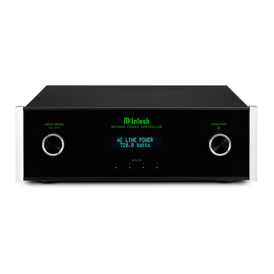
Page 17: Photos
Photos... -
Page 18: Specifications
MPC500 - Specifications (100V-120V and 220V-240V MPC500 Protection and Technologies Voltage and Power Specifications General Specifications AC Mains Protection MPC500 (100V-120V) Overall Dimensions Surge: 20kA (8x20kA) PER MODE Input Voltages Width is 17-1/2 inches (44.5cm) Modes of Protection: L-N, L-G, N-G 100 - 120 Volts AC Nominal Height is 6 inches (15.2cm) including feet... -
Page 19: Packing Instruction
400159 #10-32 x 3/4” screw needed, please call or write Customer Service Depart- 404080 #10 Flat washer ment of McIntosh Laboratory. Refer to page 2. Please see the Part List for the correct part numbers. - Page 20 McIntosh Laboratory, Inc. 2 Chambers Street Binghamton, NY 13903 www.mcintoshlabs.com The continuous improvement of its products is the policy of McIntosh Laboratory Incorporated who reserve the right to improve design without notice. Printed in the U.S.A. McIntosh Part No. 04193301...
Need help?
Do you have a question about the MPC500 and is the answer not in the manual?
Questions and answers