Table of Contents
Advertisement
Advertisement
Table of Contents

Related Manuals for McIntosh C35


Summary of Contents for McIntosh C35
- Page 2 IMPORTANT SAFETY INSTRUCTIONS THESE INSTRUCTIONS ARE TO PROTECT YOU AND THE MclNTOSH INSTRUMENT. BE SURE TO FAMILIARIZE YOURSELF WITH THEM. 1. Read all instructions - Read the safety and operating instructions before operating the instrument. 2. Retain Instructions - Retain the safety and operating instructions for future reference.
- Page 3 15. Nonuse Periods - Unplug the power cord from the 19. CAUTION: TO PREVENT ELECTICAL SHOCK DO AC power outlet when left unused for a long NOT USE THIS (POLARIZED) PLUG WITH AN period of time. EXTENSION CORD, RECEPTACLE OR OTHER 16.
-
Page 4: Table Of Contents
Contents Your C35 System Control Center will give you many INTRODUCTION 3 years of satisfactory performance. If you have any questions, please contact, INSTALLATION 4, 5 HOW TO CONNECT 6, 7, 8 CUSTOMER SERVICE FRONT PANEL CONTROLS 9, 10 Mclntosh Laboratory Inc. -
Page 5: Introduction 3
Mclntosh has earned world renown for its to be heard from the main output. technological contributions for improved sound. Volume is adjusted by a motor driven precision When you bought Mclntosh, you bought not only potentiometer. high technology, you bought technological integrity Left/right tracking accuracy is controlled to a proven by time. -
Page 6: Installation
The trouble-free life of an electronic instrument is the instrument from its plastic bag and place it greatly extended by providing sufficient ventilation to upside down on the shipping pallet. Unscrew the prevent the build-up of high internal temperatures four plastic feet from the bottom of the chassis. that cause deterioration. - Page 7 4. Saw the Panel Cutout Saw carefully on the inside of the penciled lines, First make the two long cuts and then the two short cuts. After the rectangular opening has been cut out, use a file to square the corners and smooth any irregularities in the cut edges.
-
Page 8: How To Connect
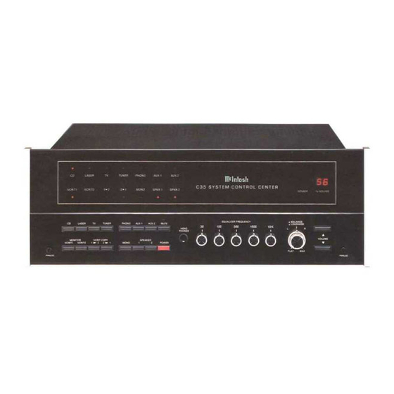
be connected to the TV INPUT. Connect the left The back cover of this manual folds out to show channel cable to the Left TV INPUT. Connect the photographs of the front and rear panels of the C 35. right channel cable to Right TV INPUT. Fold it out to assist you in locating the connectors. - Page 9 switching contacts which allow the signal to pass shielded cables with XLR type connectors to con- nect between the preamplifier and the power through them when nothing is plugged into the amplifier. jacks. When an external processor is used, the When using 2 conductor shielded cables with program is routed to the external processor from the EXTERNAL PROCESSOR TO jack and back by...
-
Page 10: How To Connect 6
interference with the main area controlled by the provide additional capacity of 1800 watts which is controlled by the AC power switch on the C 35. C 35. Additional independent REMOTE CONTROL Use these outlets to supply AC power to modules and power amplifier, can be added for each area in which remote control is desired. -
Page 11: Front Panel Controls 9
IMPORTANT: When the C 35 is operated in The back cover of this manual folds out to show MONITOR mode with VCR/T1 or VCR/T2 lighted in photographs of the front and rear panels of the C 35. the message center, the program heard will be that Fold it out to assist you in identifying and locating the from the tape recorders only. - Page 12 SPEAKER 1 and 2 J. BALANCE The SPEAKER 1 and 2 buttons can be used to The BALANCE and LOUDNESS controls are switch on or off either the SWITCHED 1 and 2 concentric. The BALANCE control (large outer AUDIO OUTPUTS jacks or the main and remote knob) adjusts the volume of the channels relative speakers when an optional SPEAKER CONTROL to each other.
-
Page 13: Performance Limits 11
PERFORMANCE LIMITS GENERAL INFORMATION Performance limits are the maximum deviation SEMICONDUCTOR COMPLEMENT from perfection permitted for a Mclntosh instrument. 49 Bipolar Transistors We promise you that when you purchase a new C 35 73 Field Effect Transistors from a Mclntosh franchised dealer, it will be capable 35 Integrated Circuits of or can be made capable of performance at or ex- 112 Diodes... -
Page 14: Performance Charts
R FREQUENCY RESPONSE CONTROLS EQUALIZE AXlMUM AND MINIMUM SET AT M FREQUENCY IN HERTZ FREQUENCY RESPONSE LOUDNES S CONTROL RESPONSE HIGH LEVEL IN FOR VARI OUS CONTROL POSITIONS TO MAIN OUT FREQUENCY IN HERTZ FREQUENCY IN HERTZ 12 PERFORMANCE CHARTS... - Page 15 RIAA EQUALIZATION CURVE FREQUENCY IN HERTZ HARMONIC DISTORTION AUX IN TO MAIN OUT 0.05 0.04 0.03 0.02 0.01 RMS OUTPUT VOLTS PERFORMANCE CHARTS 13...
-
Page 16: Block Diagram
14 BLOCK DIAGRAM... -
Page 17: Technical Description 15
many variables such as volume control position and FULL ELECTRONIC SWITCHING differences in input level. The C 35 uses active All signal switching including input tape, tape-to- loudness control circuitry. The same type of in- tape, and mono is done elctronically using J-FET field tegrated circuit operational amplifier that is used in effect analog switches. -
Page 18: Connecting Diagram
C 35 TYPICAL SIMPLIFIED CONNECTIONS AUDIO TAPE 2 TIME TIME DELAY - DELAY POWER OR REAR AMPLIFIER SPEAKERS AUDIO TAPE 1 AUDIO SECOND MAIN AREA LASER SPEAKERS OTHER SPEAKERS VISION HIGH PLAYER LEVEL SOURCE OTHER HIGH LEVEL SOURCE SIGNAL SIGNAL SECOND TURN- PROCESSOR... - Page 19 THE LOCATION OF CONTROLS The numbers and letters correspond to the paragraphs on pages 6, 7, 8, 9 and 10...
Need help?
Do you have a question about the C35 and is the answer not in the manual?
Questions and answers