
Related Manuals for Triton Aquasensation AS2000T


Summary of Contents for Triton Aquasensation AS2000T
- Page 1 Installation and Operating Instructions NSTALLERS PLEASE NOTE THESE INSTRUCTIONS ARE TO BE LEFT WITH THE USER 2180237F Nov 2000...
- Page 2 the nation’s favourite PLUMBING & HEATING SUPPLIES FREE SHIPPING SECURE PAYMENTS on all orders over £100 to mainland UK shop online with confidence FINANCE AVAILABLE PRICE MATCH spread the cost with low interest rates always get the best deals available we have H U G E R E D U C T I O N S...
-
Page 3: Table Of Contents
22 - 23 Fault finding Guarantee, service policy, etc. rear cover To ensure the product suitability for commercial and multiple installations, please contact Triton’s specification advisory service prior to installation. Telephone: (024) 7632 5491 Facsimile: (024) 7632 4564 E mail: reception@triton.plc.uk... -
Page 4: Q U A S E N S A T I O N A S 2 0 0 0 T / A
A S 2 0 0 0 T / A S 2 0 0 0 Q U A S E N S A T I O N PLUMBING NOTES an independent means of isolating the water supplies should maintenance or servicing be All installations must comply with the Local necessary. -
Page 5: Introduction
Important: The fittings on the pipe inlet elbows Replacement parts can be ordered from Triton are of the push-in type. The pipework must be cut Customer Service. See ‘spare parts’ for details and with a pipe cutter and all burrs and rough edges part numbers. -
Page 6: Key To Main Components
A S 2 0 0 0 T / A S 2 0 0 0 Q U A S E N S A T I O N KEY TO MAIN COMPONENTS Fig.1 Top pipe entry and cable entry Terminal block Cable clamp Cover screw fixing Motor cover Rear pipe entry and cable entry... -
Page 7: Site Requirements - Water
A S 2 0 0 0 T / A S 2 0 0 0 Q U A S E N S A T I O N SITE REQUIREMENTS Water Fig.3 illustrates all the incorrect connections that The installation must be in accordance with Local must be avoided. -
Page 8: General Installation Notes
A S 2 0 0 0 T / A S 2 0 0 0 Q U A S E N S A T I O N DO NOT connect to a combination cylinder unless Shower control MUST be fed from a cold there is a guaranteed 114 litre cold supply to the water storage cistern and hot water cylinder that cylinder as the shower can deliver up to 14 litres... -
Page 9: Siting Of The Shower
A S 2 0 0 0 T / A S 2 0 0 0 Q U A S E N S A T I O N SITING OF THE SHOWER Potentiometer Fig.4 (schematic view ) WARNING: THE SHOWER MUST NOT BE POSITIONED WHERE IT WILL BE SUBJECT TO FREEZING CONDITIONS. -
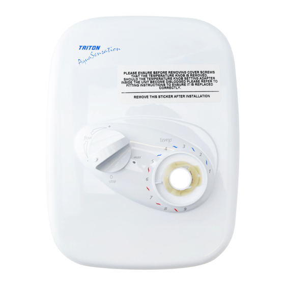
Page 10: Removing The Cover
A S 2 0 0 0 T / A S 2 0 0 0 Q U A S E N S A T I O N REMOVING THE COVER Fig.6 To remove the cover, first pull off the temperature control only (fig.6) – not the flow control. This will reveal the maximum temperature stop (fig.7). - Page 11 A S 2 0 0 0 T / A S 2 0 0 0 Q U A S E N S A T I O N Plumbing options other than those outlined in Fig.9 Cold Rear edge these fitting instructions could impair the backplate performance.
- Page 12 A S 2 0 0 0 T / A S 2 0 0 0 Q U A S E N S A T I O N Important: The inlets contain check valves, so before completing the connection of the water Fig.11 supplies to the shower flush out the pipework to remove all swarf and system debris that may cause...
-
Page 13: Fitting The Shower To The Wall
A S 2 0 0 0 T / A S 2 0 0 0 Q U A S E N S A T I O N FITTING THE SHOWER TO THE WALL Fig.14 Important: Prior to fitting the shower, ensure plumbing is flushed out, removing all debris, flux etc. -
Page 14: Electrical Connections
A S 2 0 0 0 T / A S 2 0 0 0 Q U A S E N S A T I O N ELECTRICAL CONNECTIONS WARNING: THIS UNIT MUST BE EARTHED. Fig.17 ISOLATE THE ELECTRICAL SUPPLY BEFORE PROCEEDING. -
Page 15: Commissioning And Setup Procedure
A S 2 0 0 0 T / A S 2 0 0 0 Q U A S E N S A T I O N COMMISSIONING Fig.19 WARNING: Before normal operation of the shower, it is essential that the commissioning and setup procedure are correctly completed. - Page 16 A S 2 0 0 0 T / A S 2 0 0 0 Q U A S E N S A T I O N necessary. If rear entry has been used then seal around pipes with mastic to prevent the possibility Fig.22 of water entering the wall cavity.
-
Page 17: Temperature Control Spindle Setting
A S 2 0 0 0 T / A S 2 0 0 0 Q U A S E N S A T I O N TEMPERATURE CONTROL SPINDLE SETTING Fig.25 Occasionally the knob adaptor may become Single line detached when the temperature control knobs and cover are removed from the unit. -
Page 18: Fitting The Riser Rail
A S 2 0 0 0 T / A S 2 0 0 0 Q U A S E N S A T I O N FITTING THE RISER RAIL Fig.28 WARNING: Check there are no hidden cables or pipes before drilling holes for wall plugs. Use great care when using power tools near water. -
Page 19: Fitting The Soap Dish And Sprayhead
A S 2 0 0 0 T / A S 2 0 0 0 Q U A S E N S A T I O N a screwdriver into the slot and carefully levering Fig.36 Fig.37 off the trim. F Snap the soap dish onto the rail (fig.36) below the holder assembly. -
Page 20: Operating The Shower
A S 2 0 0 0 T / A S 2 0 0 0 Q U A S E N S A T I O N OPERATING THE SHOWER Fig.44 Ensure all plumbing and electrical supplies are connected and switched on. To start the shower, rotate the flow control clockwise from the ‘stop’... -
Page 21: Adjusting The Sprayhead
A S 2 0 0 0 T / A S 2 0 0 0 Q U A S E N S A T I O N CAUTION: It is recommended that persons who Fig.48 may have difficulty understanding or operating the shower controls should not be left unattended whilst showering. -
Page 22: Adjusting The Maximum Temperature Stop
A S 2 0 0 0 T / A S 2 0 0 0 Q U A S E N S A T I O N ADJUSTING THE MAXIMUM TEMPERATURE STOP As a safety feature the shower has a built-in maximum temperature stop to prevent you accidentally exceeding your highest desired temperature. -
Page 23: Cleaning - Shower And Sprayhead
A S 2 0 0 0 T / A S 2 0 0 0 Q U A S E N S A T I O N CLEANING Fig.51 It is recommended that the shower unit, riser rail, hose etc. be cleaned using a soft cloth and that the use of abrasive or solvent cleaning fluids be avoided. -
Page 24: Cleaning The Filters
A S 2 0 0 0 T / A S 2 0 0 0 Q U A S E N S A T I O N CLEANING THE FILTERS Fig.54 NOTE: Switch off the electricity supply and Upper filter shown turn off both hot and cold water supplies to the unit before proceeding further. -
Page 25: Spare Parts
A S 2 0 0 0 T / A S 2 0 0 0 Q U A S E N S A T I O N SPARE PARTS Ref. Description Part No. 1 4 mode sprayhead white 22420080 chrome 22420100 gold 22420110 2 Brackets –... -
Page 26: Spare Parts
A S 2 0 0 0 T / A S 2 0 0 0 Q U A S E N S A T I O N SPARE PARTS Ref. Description Part No. Temperature control 83305260 (c/w override button) Maximum temperature stop 7052186 Pump &... -
Page 27: Fault Finding
4.1.1 Check water elsewhere in house and if flow or is reduced. necessary contact the local Water Company. 4.2 Shower blocked or air in 4.2.1 Switch off shower and contact Triton the system. Customer Service. 4.3 Sprayhead blocked. 4.3.1 Clean sprayhead. - Page 28 UKAS QUALITY MANAGEMENT...
-
Page 29: Service Policy
Service Policy Replacement Parts Policy In the event of a complaint occurring, the following Availability: It is the policy of Triton to maintain procedure should be followed: availability of parts for the current range of products for supply after the guarantee has expired. Stocks of...
Need help?
Do you have a question about the Aquasensation AS2000T and is the answer not in the manual?
Questions and answers