Table of Contents
Advertisement
Available languages
Available languages
Quick Links
Advertisement
Table of Contents

Related Manuals for Klipsch CP-4T


Summary of Contents for Klipsch CP-4T
- Page 1 CP-T SERIES OWNER’S MANUAL...
-
Page 2: What's Inside
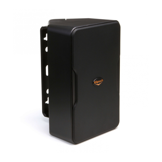
CP-T SERIES Thank you for your purchase of the Klipsch CP-T Series 70/100 The CP-4T contains a high quality, built-in 70/100 Volt transformer Volt speakers! They are designed to both withstand the rigors of with a single, fixed 5/10 watt tap while the CP-6T contains a 70/100 outdoor use while also complimenting any indoor décor. - Page 3 SPEAKER DIMENSIONS WITH/WITHOUT INCLUDED BRACKETS CP-6T CP-4T 7.0” (17.8cm) 6.9” 5.5” (17.5cm) 5.5” (14.0cm) (14.0cm) 11.0” 9.4” 8.8” 7.2” (27.9cm) (23.9cm) (22.4cm) (18.3cm) 4.7” (11.9cm) 6.1” (15.5cm) BEFORE SPEAKER INSTALLATION/CONNECTION Tools/Parts Needed For Installation: a) A level b) A pencil c) A Philips #2 screwdriver or Phillips #2 bit with a drill with a LOW TORQUE SETTING d) Two #10 or #12 2.5-3 inch (4-5cm) Pan Head Screws for each speaker for mounting into wall...
- Page 4 STEP 1 Typical Wall-Mounting With Included Bracket (Level not included) If Wall/Wall Corner or Ceiling/Wall Corner Mounting With Included Bracket Choose speaker location and run speaker wire to location. Use included template and a level to mark bracket hole locations where speaker will be mounted.
- Page 5 STEP 2 Run speaker wire (and Safety Cable if used) through hole in bracket back and attach wall bracket to wall. Use #10-#12, 2.5-3 INCH Pan Head Screws Safety Cable (if desired or required) Speaker Wires...
- Page 6 STEP 3 Remove front terminal cover then slide speaker partially onto mounted bracket arms. Channel speaker wire from rear slot through front opening while keeping speaker in position with hand. Terminal Cover...
- Page 7 STEP 4 To keep speaker on bracket while adjusting use Phillips IF USING A SPEAKER SAFETY CABLE head screwdriver (or drill/screwdriver bit AT LOW TORQUE Attach it with a 1” (2.5cm) 20-thread screw (not included) to SETTING) and partially screw in front top/bottom bracket either threaded insert on speaker rear.
-
Page 8: Mounting Options
STEP 5 With speaker still loosely on bracket arms, adjust speaker to desired angle on wall. Speaker Wires MOUNTING OPTIONS WALL WALL WALL 45˚ 45˚ 45˚ 45˚ 45˚ 45˚ 45˚ 45˚ 45˚ WALL WALL CEILING OR WALL CEILING OR WALL 45˚... - Page 9 STEP 6 CP-6T SPEAKER ONLY Connect speaker wires to terminals (in parallel with all Select desired wattage tap setting on speaker front for either speakers) with Phillips screwdriver or LOW TORQUE drill/bit. 70 or 100 Volt operation.
- Page 10 STEP 7 Once speaker is positioned as desired push back all the way back on bracket arms until flush with bracket caps and screw two partially inserted screws all the way in to lock position. STEP 8 TEST SOUND: Play music/test signal through speaker to make sure connections are tight, and, IF USING CP-6T, tap setting is correct for desired volume.
- Page 11 STEP 9 Once speaker is in the final position and tested, attach grill by pressing grill into channel encircling speaker front *SPEAKER GRILL REMOVAL: Use included grill removal tool, insert into a top corner and gently pull out. Repeat on a corner next to first one pulled, then pull out grill gently with hand.
-
Page 12: Painting The Speakers
PAINTING THE SPEAKERS Paint speaker and bracket top/ bottom caps separately. First, clean speaker cabinet and bracket top/bottom caps with mild solvent or mild detergent/water Then create a paint mask for speaker front (baffle) by tracing speaker grill on sheet of thicker, non-porous paper then cutting paper around tracing. - Page 13 CONNECTION Wire from amp to first speaker, then from first to second speaker, then from second to third speaker, ALWAYS WIRE IN PARALLEL IN A 70 OR 100 V SYSTEM! etc. (“Daisy Chain” wiring). Parallel Wiring 7.5 Watts 7.5 Watts 7.5 Watts 7.5 Watts 70/100 Volt...
-
Page 14: Speaker Placement Guidelines
SPEAKER PLACEMENT GUIDELINES +3 dB SPL and +3 dB SPL and ADDED BASS ADDED BASS Wall Positioning +3 dB SPL and +3 dB SPL and +3 dB SPL and ADDED BASS +3 dB SPL and ADDED BASS ADDED BASS ADDED BASS Speaker Spacing <=30 FT (9M) -
Page 15: Pole Mounting
Pole Mounting Inverse Square Law Using the 1/4”, 20-threaded For every doubling of distance inserts on the rear of the Klipsch from a speaker SPL is reduced by CP speakers and pole mount 6dB (-6dB) brackets from a third party... - Page 16 CP-4T SPECIFICATIONS CP-6T SPECIFICATIONS FREQUENCY RESPONSE 100Hz-22kHz +/- 3dB FREQUENCY RESPONSE 83Hz-22kHz +/- 3dB POWER HANDLING 5 watt fixed @ 70V/10 watt fixed @ 100V POWER HANDLING 75 w (300 peak) (8 ohm bypass) MAX CONTINUOUS OUTPUT 94 dB @ 70V/97 dB @ 100V...
-
Page 18: Contenu De La Boîte
LA SÉRIE CP-T Merci d’avoir acheté les enceintes Klipsch 70/100 V de la série à l’intersection d’un mur et d’un plafond, pour une apparence CP-T ! Elles sont conçues autant pour endurer les rigueurs d’une extrêmement esthétique qui augmente le volume global des graves. - Page 19 DIMENSIONS DES ENCEINTES AVEC/SANS LES SUPPORTS FOURNIS CP-6T CP-4T 7.0” (17.8cm) 6.9” 5.5” (17.5cm) 5.5” (14.0cm) (14.0cm) 11.0” 9.4” 8.8” 7.2” (27.9cm) (23.9cm) (22.4cm) (18.3cm) 4.7” (11.9cm) 6.1” (15.5cm) OUTILS/PIÈCES NÉCESSAIRES POUR L’INSTALLATION Outils/pièces nécessaires pour l’installation : a) Un niveau b) Un crayon c) Un tournevis cruciforme taille 2 ou un embout cruciforme nº...
- Page 20 ÉTAPE 1 Montage mural typique avec le support fourni Montage en angle ou à l’intersection d’un mur et d’un plafond avec le support fourni Choisissez l’emplacement de l’enceinte et acheminez du fil d’enceinte jusqu’à cet endroit. Utilisez le gabarit fourni et un niveau pour marquer l’emplacement des trous du support à l’endroit où l’enceinte sera installée.
-
Page 21: Safety Cable
ÉTAPE 2 Passez le fil d’enceinte (et le câble de sécurité, le cas échéant) dans le trou situé à l’arrière du support et fixez le support mural au mur. Utilisez des vis à tête cylindrique bombée de 5 ou 5,5 mm de diamètre et 60 à 75 mm de longueur Safety Cable Câble de sécurité... - Page 22 ÉTAPE 3 Retirez le cache des bornes sur le devant, puis glissez partiellement l’enceinte sur les bras du support installé. Acheminez le fil d’enceinte de la fente arrière jusqu’à l’orifice avant, tout en maintenant l’enceinte en place avec une main. Cache des bornes...
- Page 23 ÉTAPE 4 Pour maintenir l’enceinte sur le support pendant POUR UTILISER UN CÂBLE DE SÉCURITÉ AVEC L’ENCEINTE l’ajustement, utilisez un tournevis cruciforme (ou une Fixez-le à l’aide d’une vis (non fournie) de 2,5 cm, 20 filets visseuse réglée sur le COUPLE MINIMUM) et vissez par pouce, à...
- Page 24 ÉTAPE 5 With speaker still loosely on bracket arms, adjust speaker to desired angle on wall. Speaker Wires WALL WALL WALL 45˚ 45˚ 45˚ 45˚ 45˚ 45˚ 45˚ 45˚ 45˚ WALL WALL PLAFOND OU MUR CEILING OR WALL CEILING OR WALL 45˚...
- Page 25 ÉTAPE 6 ENCEINTE CP-6T UNIQUEMENT Raccordez les fils d’enceinte aux bornes (en parallèle avec Sélectionnez la puissance de sortie désirée sur le devant de toutes les enceintes) avec un tournevis cruciforme ou une l’enceinte pour un fonctionnement en 70 ou 100 V. visseuse réglée sur le...
- Page 26 ÉTAPE 7 Une fois l’enceinte dans la position désirée, poussez-la à fond sur les bras du support jusqu’à venir en contact avec les capuchons du support, puis vissez complètement les deux vis partiellement insérées pour verrouiller la position. ÉTAPE 8 TESTEZ LE SON : Passez de la musique ou un signal de test par l’enceinte pour vous assurer que les branchements sont solides et, SI VOUS UTILISEZ LE CP-6T, que la sortie...
- Page 27 ÉTAPE 9 Une fois l’enceinte en position finale et testée, fixez la grille en l’insérant à la main dans la rainure suivant le périmètre de l’enceinte. *RETRAIT DE LA GRILLE DE L’ENCEINTE : Utilisez l’outil fourni pour retirer la grille, insérez-le dans un coin supérieur et tirez doucement vers vous.
-
Page 28: Peinture Des Enceintes
PEINTURE DES ENCEINTES Peignez séparément les enceintes et les capuchons supérieurs/inférieurs des supports. Nettoyez d’abord les enceintes et les capuchons supérieurs/inférieurs des supports avec un solvant doux ou un détergent doux et de l’eau. Ensuite, créez un cache à peinture pour le devant de l’enceinte (baffle) WHITE-SPIRIT DÉTERGENT... - Page 29 BRANCHEMENT Branchez l’amplificateur à la première enceinte, puis la première enceinte à la deuxième, la deuxième BRANCHEZ TOUJOURS EN PARALLÈLE à la troisième, etc. (branchement en « guirlande »). DANS UN SYSTÈME DE 70 OU 100 V! Parallel Wiring Branchement en parallèle d’un 7.5 Watts 7.5 Watts 7.5 Watts...
- Page 30 CONSIGNES POUR LE POSITIONNEMENT DES ENCEINTES +3 dB de NIVEAU DE PRESSION ACOUSTIQUE et +3 dB SPL and ACCENTUATION DES GRAVES +3 dB SPL and ADDED BASS ADDED BASS Positionnement au mur +3 dB SPL and +3 dB de NIVEAU DE +3 dB de NIVEAU DE +3 dB SPL and PRESSION ACOUSTIQUE et...
- Page 31 1/4”, 20 filets par pouce, distance à une enceinte, le niveau à l’arrière des enceintes de pression acoustique est réduit de Klipsch de la série CP et 6 dB (-6 dB) des brides d’installation sur poteau disponibles auprès d’un...
- Page 32 CARACTÉRISTIQUES DU MODÈLE KLIPSCH CP-4T CARACTÉRISTIQUES DU MODÈLE KLIPSCH CP-6T RÉPONSE EN FRÉQUENCE 100 Hz - 22 kHz +/- 3 dB RÉPONSE EN FRÉQUENCE 83 Hz - 22 kHz +/- 3 dB PUISSANCE ADMISSIBLE 5 W fixe à 70 V/10 W fixe à 100 V PUISSANCE ADMISSIBLE 75 W (300 W en crête) (dérivation de...
-
Page 34: Contenido Del Paquete
La dispersión de trompeta de 90° x 90° asegura una cobertura amplia y El CP-4T tiene un transformador de voltaje integrado de 70/100 uniforme en colocación horizontal o vertical. Los woofers de largo voltios de alta calidad con una toma fija única de 5/10 W. El CP-6T desplazamiento se combinan con puertos de salida frontal para tiene un transformador de 70/100 voltios con tomas de 3.75/7.5... - Page 35 DIMENSIONES DEL ALTAVOZ CON Y SIN LOS SOPORTES INCLUIDOS CP-6T CP-4T 7.0” (17.8cm) 6.9” 5.5” (17.5cm) 5.5” (14.0cm) (14.0cm) 11.0” 9.4” 8.8” 7.2” (27.9cm) (23.9cm) (22.4cm) (18.3cm) 4.7” (11.9cm) 6.1” (15.5cm) HERRAMIENTAS Y PIEZAS NECESARIAS PARA LA INSTALACIÓN Herramientas y piezas necesarias para la instalación: a) Un nivel b) Un lápiz...
- Page 36 PASO 1 Montaje estándar en la pared con el soporte incluido O BIEN Montaje de esquina de pared a pared o esquina de pared a cielo raso con el soporte incluido O BIEN Escoja la ubicación del altavoz y encamine el cable. Con la plantilla incluida y un nivel, marque la posición de los agujeros para el soporte en que se va a montar el altavoz.
- Page 37 PASO 2 Encamine el cable de altavoz (y el cable de seguridad si se va a instalar) a través del agujero en la parte de atrás del soporte y fije el soporte en la pared. USE tornillos de cabeza troncocónica Nº 10 o Nº 12 de 2.5 a 3 plg.
- Page 38 PASO 3 Quite la cubierta de la terminal de adelante y luego deslice el altavoz parcialmente sobre los brazos del soporte montado. Encamine el cable de altavoz desde la ranura de atrás a través de la abertura de adelante manteniendo el altavoz en posición con una mano. Cubierta de terminal...
- Page 39 PASO 4 O BIEN Para mantener el altavoz en el soporte mientras se hacen SI SE INSTALA UN CABLE DE SEGURIDAD DE ALTAVOZ los ajustes, atornille parcialmente los tornillos de soporte Fíjelo con un tornillo de 2.5 cm (1 plg.) de largo con rosca de de adelante de abajo y de arriba (2 a 3 vueltas) con un 20 vueltas por plg.
- Page 40 PASO 5 Estando flojo en los brazos del soporte, oriente el altavoz según el ángulo deseado en la pared. Speaker Wires WALL WALL WALL 45˚ 45˚ 45˚ 45˚ 45˚ 45˚ O BIEN O BIEN 45˚ 45˚ 45˚ PARED CIELO RASO O PARED WALL WALL CEILING OR WALL...
- Page 41 PASO 6 SOLO PARA EL ALTAVOZ CP-6T Conecte los cables de altavoz a las terminales (en paralelo en En la parte de adelante del altavoz, seleccione la todos los altavoces) con un destornillador Phillips o una broca configuración de toma de potencia deseada para de taladro/destornillador DE BAJA TORSIÓN.
- Page 42 PASO 7 Una vez que el altavoz esté en la posición deseada, empújelo hasta el fondo sobre los brazos del soporte hasta que quede contra las cubiertas de soporte y atornille hasta el fondo los tornillos parcialmente atornillados. PASO 8 PRUEBA DE SONIDO: Envíe una señal de música o de prueba al altavoz para asegurarse de que las conexiones estén apretadas y, SI SE TRATA DE UN CP-6T, que la configuración...
- Page 43 PASO 9 Une fois l’enceinte en position finale et testée, fixez la grille en l’insérant à la main dans la rainure suivant le périmètre de l’enceinte. * DESMONTAJE DE LA REJILLA DEL ALTAVOZ: Inserte la herramienta de desmontaje que se incluye en una de las esquinas superiores y jale cuidadosamente hacia afuera.
- Page 44 PINTURA DE LOS ALTAVOCES Pinte los altavoces y las cubiertas de soporte de arriba y de abajo por separado. Primero, limpie la caja del altavoz y las tapas de soporte de arriba y de abajo con un solvente suave o un detergente suave y agua.
- Page 45 CONEXIÓN Cablee desde el amplificador al primer altavoz, luego desde el primer al segundo altavoz, luego del CABLEE SIEMPRE EN segundo al tercer altavoz, etc. (Cableado en “cadena de margarita”). PARALELO EN UN SISTEMA DE 70 O 100 VOLTIOS. Parallel Wiring Cableado en paralelo para 7.5 Watts 7.5 Watts...
- Page 46 PAUTAS DE UBICACIÓN DE ALTAVOCES +3 dB SPL and +3 dB SPL y BAJOS ADICIONALES +3 dB SPL and ADDED BASS ADDED BASS Posicionamiento en la pared +3 dB SPL and +3 dB SPL and +3 dB SPL y BAJOS +3 dB SPL y BAJOS +3 dB SPL and ADDED BASS...
- Page 47 (SPL) se reduce en 6 dB (-6 dB) de los altavoces CP de Klipsch y soportes de montaje en EJEMPLO: postes de otro proveedor, los...
- Page 48 ESPECIFICACIONES DEL CP-4T DE KLIPSCH ESPECIFICACIONES DEL CP-6T DE KLIPSCH RESPUESTA DE FRECUENCIAS 100 Hz a 22 kHz +/- 3 dB RESPUESTA DE FRECUENCIAS 83 Hz a 22 kHz +/- 3 dB 75 W (300 máx.) (paso por alto de 8 Ω)
- Page 50 Das 90°x 90° Abstrahlmuster des Hornlautsprechers sorgt sowohl bei horizontaler als auch bei vertikaler Platzierung für eine breite, Der CP-4T enthält einen hochwertigen 70/100 Volt-Trafo mit einem gleichmäßige Abdeckung. Die langhubigen Tieftöner werden mit nach festen 5/10 Watt Trafoabgang, während der CP-6T einen 70/100 vorne gerichteten Bassreflexöffnungen kombiniert, um bei jeder...
- Page 51 LAUTSPRECHERABMESSUNGEN MIT/OHNE BEILIEGENDE BEFESTIGUNGEN CP-6T CP-4T 7.0” (17.8cm) 6.9” 5.5” (17.5cm) 5.5” (14.0cm) (14.0cm) 11.0” 9.4” 8.8” 7.2” (27.9cm) (23.9cm) (22.4cm) (18.3cm) 4.7” (11.9cm) 6.1” (15.5cm) FÜR DIE INSTALLATION NÖTIGE WERKZEUGE UND TEILE Für die Installation nötige Werkzeuge und Teile:...
- Page 52 1. SCHRITT Standardmäßige Wandmontage mit beiliegender Befestigung ODER Wand-/Eckenmontage oder Decken-/Eckenmontage mit beiliegender Befestigung ODER Wählen Sie die Montageorte und verlegen Sie die Lautsprecherkabel. Verwenden Sie die beiliegende Schablone und eine Wasserwaage, um die Löcher für die Befestigung zu markieren.
- Page 53 2. SCHRITT Führen Sie das Lautsprecherkabel (und ggf. das Sicherheitskabel) durch das Loch hinten an der Befestigung und schrauben Sie die Befestigung an die Wand. Nr. 10 oder Nr. 12 2,5-3-Zoll Flachkopfblechschrauben verwenden Safety Cable Sicherheitskabel (if desired or required) (falls gewünscht oder erforderlich) ODER Speaker...
- Page 54 3. SCHRITT Entfernen Sie die Anschlussabdeckung vorne am Lautsprecher und schieben Sie den Lautsprecher teilweise auf die Befestigungsarme. Führen Sie das Lautsprecherkabel durch den hinteren Schlitz in die vordere Öffnung und halten Sie dabei den Lautsprecher mit der Hand fest. Anschlussabdeckung...
- Page 55 4. SCHRITT ODER Damit der Lautsprecher während der Justierung auf der BEI VERWENDUNG EINES LAUTSPRECHER-SICHERHEITSKABELS Befestigung bleibt, drehen Sie die vorderen oberen/unteren Befestigen Sie es mit einer (nicht mitgelieferten) 1 Zoll Befestigungsschrauben mit dem Kreuzschlitzschraubendreher (2,54 cm) langen Schraube (Gewindesteigung 20/Zoll) an (oder einer Bohrmaschine mit Schraubeinsatz AUF einem der Gewindelöcher an der Rückseite des Lautsprechers.
- Page 56 5. SCHRITT Während der Lautsprecher noch locker auf den Befestigungsarmen sitzt, stellen Sie den gewünschten Winkel zur Wand ein. Speaker Wires WALL WALL WALL 45˚ 45˚ 45˚ 45˚ 45˚ 45˚ ODER ODER 45˚ 45˚ 45˚ WAND DECKE ODER WAND WALL WALL CEILING OR WALL CEILING OR WALL...
- Page 57 6. SCHRITT NUR FÜR CP-6T LAUTSPRECHER Verbinden Sie mit dem Kreuzschlitzschraubendreher (oder Wählen Sie die gewünschte Trafoabgang-Einstellung (in einer Bohrmaschine mit Schraubeinsatz AUF NIEDRIGER Watt) an der Vorderseite des Lautsprechers für den 70- oder DREHMOMENTEINSTELLUNG) die Lautsprecherkabel mit den 100-Volt-Betrieb. Anschlüssen (parallel zu allen Lautsprechern).
- Page 58 7. SCHRITT Sobald der Lautsprecher nach Wunsch platziert wurde, drücken Sie ihn an den Befestigungsarmen ganz nach hinten, bis er mit den Befestigungsabdeckungen bündig ist, und schrauben die beiden teilweise eingeführten Schrauben bis auf die Sperrposition ein. 8. SCHRITT SOUNDTEST: Geben Sie Musik oder ein Testsignal wieder, um sicherzustellen, dass die Verbindungen fest sitzen, und um beim CP-6T zu prüfen, ob die Abgangseinstellung für die gewünschte Lautstärke richtig ist.
- Page 59 9. SCHRITT Sobald der Lautsprecher sich in der Endposition befindet und getestet wurde, befestigen Sie den Lautsprechergrill, indem Sie diesen mit der Hand in den Kanal an der Vorderseite des Lautsprechers eindrücken. *ABNAHME DES LAUTSPRECHERGRILLS: Verwenden Sie das beiliegende Werkzeug zur Abnahme des Lautsprechergrills, indem Sie es in die obere Ecke einführen und vorsichtig herausziehen.
-
Page 60: Lackieren Der Lautsprecher
LACKIEREN DER LAUTSPRECHER Lackieren Sie den Lautsprecher und die oberen/ unteren Befestigungsabdeckungen separat. Reinigen Sie zuerst das Lautsprechergehäuse und die oberen/ unteren Befestigungsabdeckungen mit einem milden Lösungsmittel oder milden Waschmittel und Wasser. Erstellen Sie dann eine Lackierschablone für die Vorderseite des Lautsprechers (Schallwand), indem Sie den Lautsprechergrill auf einem Blatt dicken, WASCHBENZIN... - Page 61 VERBINDUNG Vom Verstärker zum ersten Lautsprecher, dann vom ersten zum zweiten, dann vom zweiten BEI EINEM 70- ODER zum dritten usw. (sogenannte „Daisy Chain“-Verbindung) verdrahten. 100-V-SYSTEM IMMER PARALLELSCHALTUNG VERWENDEN! Parallel Wiring Parallelschaltung 7.5 Watts 7.5 Watts 7.5 Watts 7.5 Watts 70/100 Volt 70/100-Volt-Leitungsverstärker Line Distribution Amp...
- Page 62 RICHTLINIEN FÜR DIE LAUTSPRECHERPLATZIERUNG +3 dB SPL and +3 dB Schalldruck und MEHR BASS +3 dB SPL and ADDED BASS ADDED BASS Wandplatzierung +3 dB SPL and +3 dB SPL and +3 dB Schalldruck und +3 dB Schalldruck und +3 dB SPL and ADDED BASS +3 dB SPL and ADDED BASS...
- Page 63 RICHTLINIEN FÜR DIE LAUTSPRECHERPLATZIERUNG Pfostenmontage Abstandsgesetz: Unter Verwendung der Für jede Verdoppelung des Abstands Viertelzoll-Gewinde an vom Lautsprecher reduziert sich der der Rückseite der Klipsch Schalldruck um 6 dB (-6 dB) CP-Lautsprecher und von Stangenbefestigungen eines BEISPIEL Drittanbieters können die Lautsprecherempfindlichkeit:...
- Page 64 KLIPSCH CP-4T TECHNISCHE DATEN KLIPSCH CP-6T TECHNISCHE DATEN FREQUENZGANG 100 Hz - 22 kHz +/- 3dB FREQUENZGANG 83 Hz - 22 kHz +/- 3dB BELASTBARKEIT 5 Watt Festwert bei 70V / 10 Watt Fest- BELASTBARKEIT 75 Watt (300 Spitzenleistung) wert bei 100V (8-Ohm-Bypass) MAX.
-
Page 66: Conteúdo Da Embalagem
SÉRIE CP-T Agradecemos sua preferência pelas caixas acústicas Klipsch Série A CP-4T tem um transformador embutido de alta qualidade de CP-T de 70/100 volts! Elas foram projetadas para suportar os rigores 70/100 V com uma derivação fixa de 5/10 W, enquanto a CP-6T do uso ao ar livre e também complementar qualquer decoração... - Page 67 DIMENSÕES DAS CAIXAS ACÚSTICAS COM/SEM OS SUPORTES INCLUÍDOS CP-6T CP-4T 7.0” (17.8cm) 6.9” 5.5” (17.5cm) 5.5” (14.0cm) (14.0cm) 11.0” 9.4” 8.8” 7.2” (27.9cm) (23.9cm) (22.4cm) (18.3cm) 4.7” (11.9cm) 6.1” (15.5cm) FERRAMENTAS E PEÇAS NECESSÁRIAS PARA A INSTALAÇÃO Ferramentas e peças necessárias para a instalação: a) Nível...
- Page 68 ETAPA 1 Instalação padrão em parede com o suporte fornecido Instalação em canto entre paredes ou entre teto e parede com o suporte fornecido Escolha as localizações das caixas acústicas e passe a fiação. Use o modelo fornecido e um nível para marcar os locais dos furos do suporte onde a caixa acústica será...
- Page 69 ETAPA 2 Passe o cabo para a caixa acústica (e o cabo de segurança se for usado) pelo orifício atrás do suporte e prenda o suporte na parede. Use parafusos de cabeça abaulada número 10 ou 12, de 2,5 a 3” (6,4 a 7,6 cm) Safety Cable Cabo de segurança (if desired or required)
- Page 70 ETAPA 3 Remova a cobertura frontal dos terminais e, em seguida, deslize parcialmente a caixa acústica nos braços do suporte instalado. Passe o cabo para a caixa acústica da ranhura traseira pela abertura frontal, mantendo manualmente a caixa acústica na posição. Cobertura dos terminais...
- Page 71 ETAPA 4 Para manter a caixa acústica no suporte durante o ajuste, CASO USE UM CABO DE SEGURANÇA DE CAIXA ACÚSTICA use uma chave de fenda Phillips (ou furadeira/ponta Phillips Prenda-o com um parafuso de 1” (2,5 cm) com 20 roscas (não com AJUSTE DE BAIXO TORQUE) e rosqueie parcialmente os fornecido) em um dos orifícios roscados na parte de trás da parafusos frontais superior e inferior do suporte (2 a 3 voltas) e,...
- Page 72 ETAPA 5 Com a caixa acústica ainda frouxa nos braços do suporte, coloque-a no ângulo desejado na parede. Speaker Wires WALL WALL WALL 45˚ 45˚ 45˚ 45˚ 45˚ 45˚ 45˚ 45˚ 45˚ PAREDE TETO OU PAREDE WALL WALL CEILING OR WALL CEILING OR WALL 45˚...
- Page 73 ETAPA 6 SOMENTE CAIXA ACÚSTICA CP-6T Conecte os cabos para caixa acústica aos terminais (em Selecione a configuração de potência da derivação desejada paralelo em todas as caixas acústicas) com uma chave de na frente da caixa acústica para 70 ou 100 V. fenda Phillips ou furadeira/ponta de BAIXO TORQUE.
- Page 74 ETAPA 7 Assim que a caixa acústica estiver na posição desejada, empurre-a totalmente para trás ao longo dos braços do suporte até que fique alinhada com as coberturas do suporte e aperte totalmente os dois parafusos parcialmente inseridos para fixar a unidade. ETAPA 8 TESTE O SOM: Reproduza música ou o sinal de teste na caixa acústica para verificar se as conexões estão bem feitas e, SE...
- Page 75 ETAPA 9 Assim que a caixa acústica estiver na posição final e tiver sido testada, instale manualmente a grade pressionando-a no canal que circunda a parte frontal da caixa acústica. *REMOÇÃO DA GRADE DA CAIXA ACÚSTICA: Insira a ferramenta de remoção da grade fornecida em um dos cantos superiores e puxe com cuidado para fora.
- Page 76 PINTURA DAS CAIXAS ACÚSTICAS Pinte as caixas acústicas e as coberturas superior/inferior dos suportes separadamente. Primeiro, limpe a superfície e as coberturas superior e inferior do suporte da caixa acústica com solvente ou detergente neutro e água. Em seguida, crie uma proteção de pintura para ser colocada na AGUARRÁS ÁGUA +...
- Page 77 CONEXÃO Faça a conexão do amplificador à primeira caixa acústica, depois da primeira para a segunda caixa acústica, depois da segunda para a terceira caixa acústica, etc. (conexão “em margarida”). A CONEXÃO DEVE SER SEMPRE EM PARALELO EM UM SISTEMA DE 70 OU 100 V! Parallel Wiring Amplificador de distribuição em 7.5 Watts...
- Page 78 DIRETRIZES DE POSICIONAMENTO DAS CAIXAS ACÚSTICAS +3 dB SPL and +3 dB SPL e GRAVES ADICIONADOS +3 dB SPL and ADDED BASS ADDED BASS Posicionamento em parede +3 dB SPL and +3 dB SPL and +3 dB SPL e GRAVES +3 dB SPL e GRAVES +3 dB SPL and ADDED BASS...
- Page 79 Y (2 m) = 88 dB 1/4” localizados na parte de trás Z (4 m) = 85 dB das caixas acústicas Klipsch CP e suportes para instalação em colunas de terceiros. Outras orientações: •...
- Page 80 ESPECIFICAÇÕES DA KLIPSCH CP-4T ESPECIFICAÇÕES DA KLIPSCH CP-6T RESPOSTA DE FREQUÊNCIA 100 Hz a 22 kHz +/- 3 dB RESPOSTA DE FREQUÊNCIA 83 Hz a 20 kHz +/- 3 dB POTÊNCIA MÁXIMA PERMISSÍVEL 5 W fixos a 70 V/10 W fixos a 100 V POTÊNCIA MÁXIMA PERMISSÍVEL...
-
Page 82: Contenuto Della Confezione
Il diagramma di dispersione Nel modello CP-4T è integrato un trasformatore di alta qualità da della tromba a 90°x 90° assicura una copertura ampia e uniforme 70/100 volt dotato di singola presa fissa da 5/10 watt, mentre il modello indipendentemente dalla collocazione, orizzontale o verticale. - Page 83 DIMENSIONI DEGLI ALTOPARLANTI CON/SENZA LE STAFFE FORNITE CP-6T CP-4T 7.0” (17.8cm) 6.9” 5.5” (17.5cm) 5.5” (14.0cm) (14.0cm) 11.0” 9.4” 8.8” 7.2” (27.9cm) (23.9cm) (22.4cm) (18.3cm) 4.7” (11.9cm) 6.1” (15.5cm) COMPONENTI/ATTREZZI NECESSARI PER L’INSTALLAZIONE Componenti/attrezzi necessari per l’installazione a) Una livella b) Una matita c) Un cacciavite con testa a croce Philips n.
- Page 84 Tipico fissaggio a parete con la staffa fornita OPPURE Se si eseguirà il fissaggio a un angolo tra due pareti o tra una parete e il soffitto con la staffa fornita OPPURE Scegliere il punto in cui collocare ciascun altoparlante e disporne il cavo. Usare la dima fornita e una livella per contrassegnare i punti in cui praticare i fori per la staffa dell’altoparlante.
-
Page 85: Safety Cable
Fare passare il cavo dell’altoparlante (e il cavo di sicurezza se adoperato) attraverso il foro nella parte posteriore della staffa e fissare quest’ultima alla parete. Usare viti a testa tronco-conica n. 10 – 12, da 6,35 – 7,62 mm Safety Cable Cavo di sicurezza (if desired or required) (se desiderato o necessario) - Page 86 Rimuovere il coperchio terminale anteriore, quindi fare scorrere l’altoparlante parzialmente sui bracci della staffa già fissata. Fare passare il cavo dell’altoparlante dalla scanalatura posteriore attraverso l’apertura anteriore mentre si tiene fermo l’altoparlante con una mano. Coperchio terminale...
- Page 87 OPPURE Per mantenere l’altoparlante sulla staffa mentre se ne regola SE SI UTILIZZA UN CAVO DI SICUREZZA DELL’ALTOPARLANTE la posizione, avvitare parzialmente dalla parte anteriore con il Fissarlo con una vite lunga 1” (2,5 cm) e filettatura 1/4”- 20 cacciavite Phillips (o con un trapano/avvitatore REGOLATO SU UN (non fornita) a uno dei due inserti filettati presenti sulla parte BASSO VALORE DI COPPIA) le viti superiore/inferiore della staffa posteriore dell’altoparlante.
- Page 88 Con l’altoparlante ancora non fissato del tutto sui bracci della staffa, regolare l’angolazione dell’altoparlante come si desidera sulla parete. Speaker Wires WALL WALL WALL 45˚ 45˚ 45˚ 45˚ 45˚ 45˚ OPPURE OPPURE 45˚ 45˚ 45˚ PARETE SOFFITTO O PARETE WALL WALL CEILING OR WALL CEILING OR WALL...
- Page 89 SOLO PER GLI ALTOPARLANTI CP-6T Collegare i cavi dell’altoparlante ai suoi terminali (in parallelo Selezionare uno dei valori di potenza disponibili con tutti gli altoparlanti) con il cacciavite Phillips o usando un dall’altoparlante per il funzionamento a 70 o 100 volt. trapano regolato sul VALORE MINIMO DI COPPIA.
- Page 90 Dopo aver posizionato l’altoparlante come desiderato, spingerlo completamente indietro sui bracci della staffa finché non è a filo con i coperchi della staffa e bloccarlo avvitando completamente le due viti inserite parzialmente. VERIFICA DEL SUONO: riprodurre con l’altoparlante della musica o un segnale di prova per accertarsi che le connessioni siano salde e, SE SI USA UN CP-6T, che la presa del trasformatore selezionata sia appropriata per il volume desiderato.
- Page 91 Dopo che l’altoparlante è nella posizione finale e se ne è verificata la funzionalità, fissare manualmente la griglia all’altoparlante premendola sul canale lungo il perimetro della sua parte anteriore. *RIMOZIONE DELLA GRIGLIA DELL’ALTOPARLANTE Inserire l’apposito attrezzo, fornito, in un angolo superiore e con cautela tirarla in fuori.
-
Page 92: Verniciatura Degli Altoparlanti
VERNICIATURA DEGLI ALTOPARLANTI Verniciare separatamente l’altoparlante e i coperchi superiore/inferiore della staffa. Anzitutto, pulire la cassa dell’altoparlante e i coperchi superiore/inferiore della staffa con un solvente delicato o con acqua e un detergente delicato. Quindi creare una maschera da verniciatura per la parte anteriore (diaframma) dell’altoparlante ACQUARAGIA DETERGENTE... - Page 93 COLLEGAMENTO Eseguire il cablaggio dall’amplificatore al primo altoparlante, da questo al secondo, da questo al terzo ESEGUIRE IL COLLEGAMENTO SEMPRE IN PARALLELO IN ecc. (collegamento “in serie”). UN IMPIANTO A 70 O 100 VOLT! Parallel Wiring Collegamento in parallelo da un 7.5 Watts 7.5 Watts 7.5 Watts...
- Page 94 LINEE GUIDA PER LA COLLOCAZIONE DEGLI ALTOPARLANTI +3 dB SPL and SPL PARI A +3 dB e BASSI AGGIUNTI +3 dB SPL and ADDED BASS ADDED BASS Collocazione sulla parete +3 dB SPL and +3 dB SPL and SPL PARI A +3 dB e SPL PARI A +3 dB e +3 dB SPL and ADDED BASS...
- Page 95 Ogni volta che si raddoppia la distanza posteriore degli altoparlanti da un altoparlante, il livello di pressione Klipsch CP e le staffe per sonora (SPL) si riduce di 6 dB. fissaggio a un palo fornite da terzi, è possibile fissare gli...
- Page 96 DATI TECNICI DEL KLIPSCH CP-4T DATI TECNICI DEL KLIPSCH CP-6T RISPOSTA IN FREQUENZA 100 Hz – 20 kHz +/- 3 dB RISPOSTA IN FREQUENZA 83 Hz – 20 kHz +/- 3 dB POTENZA MASSIMA 5 watt costanti a 70 V / 10 watt costanti...
- Page 98 KLIPSCH CP-T 感谢您选购 Klipsch CP-T 系列 70/100 伏扬声器。 该系列扬声器的设 CP-4T 包含配备了单个抽头的优质内置式 70/100 伏变压器,其抽头设 计匠心独具,既能在严酷的室外环境中使用,又能为任何室内装饰锦上 定值固定为 5/10 瓦;而 CP-6T 则包含配备了多个抽头的变压器,其抽 添花。 无论是水平布置还是垂直布置,其 90°x 90° 号角覆盖角度可确 头设定值为 3.75/7.5 瓦、7.5/15 瓦、15/30 瓦和 30 瓦。 为实现 8 欧姆 保宽广均匀的覆盖范围。 长冲程低音炮与前推端口相得益彰,无论如何 的工作条件,CP-6T 还具有 8 欧姆的旁路设定值。...
- Page 99 扬声器尺寸(含/不含随附支架): CP-6T CP-4T 7.0” (17.8cm) 6.9” 5.5” (17.5cm) 5.5” (14.0cm) (14.0cm) 11.0” 9.4” 8.8” 7.2” (27.9cm) (23.9cm) (22.4cm) (18.3cm) 4.7” (11.9cm) 6.1” (15.5cm) 安装所需之工具/零件 安装所需之工具/零件 (a) 水平仪 (b) 铅笔 (c) 2 号十字螺丝刀或 2 号十字螺丝刀刀头(配有钻头,低转矩设定值) (d) 每个扬声器需要两个 10 号 或 12 号 2.5 英寸至 3 英寸(6.35 至 7.62 厘米)盘头螺钉,用于将...
- Page 100 第 1 步 如果采用随附支架进行标准的壁挂式安装 或 如果采用随附支架在墙壁/墙角或天花板/墙壁角落安装 或 选择扬声器安装位置,然后敷设导线。 使用随附模板和水平仪标示即将安装扬声器的支架孔位置。...
- Page 101 第 2 步 通过支架背部的开孔敷设扬声器导线和安全索(如果使用安全索),然后将壁挂支架安装在墙壁上。 使用 10 号至 12 号 2.5 英寸至 3 英寸 盘头螺钉 Safety Cable 安全索 (如果需要或要求使用) (if desired or required) 或 Speaker 扬声器导线 Wires...
- Page 102 第 3 步 卸下前端子盖,然后将扬声器部分滑入安装支架臂。 通过前面开孔从后槽敷设扬声器导线,同时用 手将扬声器保持在位。 端子盖...
- Page 103 第 4 步 或 调整时为了将扬声器保持在支架上,使用十字螺丝刀(或低转矩钻头/螺 丝刀刀头)将前面的顶部/底部支架螺钉部分旋入(大约旋入 2 至 3 圈) ,然后向外轻拉扬声器,以松开支架 3/4 处的位置。 S如果使用扬声器安全索 用 1 英寸(2.5 厘米) 20 牙螺纹螺钉(自备)将其连接至扬声器背面任 一螺纹插孔。 如果使用钻头和螺丝刀刀头,请选用低转矩设定值。...
- Page 104 第 5 步 在紧固支架臂上的扬声器之前,在墙壁上将扬声器调节至所需角度。 Speaker Wires WALL WALL WALL 45˚ 45˚ 45˚ 45˚ 45˚ 45˚ 或 或 45˚ 45˚ 45˚ 墙壁 天花板或墙壁 WALL WALL CEILING OR WALL CEILING OR WALL 45˚ 45˚ 45˚ 45˚ 45˚ 45˚...
- Page 105 第 6 步 仅限 CP-6T 扬声器 用十字螺丝刀或低转矩钻具/刀头将扬声器导线连接至相应端子(与扬声 在扬声器前部选择想要的抽头功率设定值,用于满足 70 伏或 100 伏工 器平行)。 作条件。...
- Page 106 第 7 步 一旦扬声器就位,将扬声器在支架臂上完全推回,直到与支架盖平齐, 然后将两个部分插入的螺钉完全旋入锁止位置 。 第 8 步 声音测试:通过扬声器播放音乐/测试信号,以确保连接紧密,并且如 果使用 CP-6T,确保抽头设定值与所需的音量匹配。...
- Page 107 第 9 步 一旦扬声器安装到位并通过测试,安装扬声器格栅(安装方 法:用手将格栅压入环绕扬声器前部的凹槽)。 * 扬声器格栅拆卸方法:使用随附格栅拆卸工具,将其插入上角,然后轻轻拉 出。 重复上述步骤,拉出其邻角,然后用一只手轻轻拉出格栅。 注: 设计的 格栅紧贴在扬声器上,恰好能够与扬声器紧密贴合。 连续的格栅拆卸/重新插 入可能会导致格栅松动,从而产生振动或滑动。 使用不同的安装支架(不使用随附支架) 所有 CP 系列扬声器均在背面底部设立了一个 1/4 英寸 20 牙螺纹插 孔,您可利用该插孔安装其他兼容支架。 还提供了一个用于安装安全索 的 1/4 英寸 20 牙螺纹插孔。...
- Page 108 扬声器上漆 扬声器与支架顶盖/底盖分开上漆。 首先,使用中性溶剂或中性洗涤 剂/水清洁扬声器音箱和支架顶盖/ 底盖。 然后为扬声器前部(反射板)制作 一张油漆罩,制作方法:在一张无 孔厚纸上描出扬声器格栅的轮廓, 溶剂油 中性洗涤剂 然后沿该轮廓将纸张裁切下来。 + 水 将格栅纸罩放置在扬声器前部( 盖在反射板上),确保该纸罩还 遮住了格栅凹槽,然后用双面胶 带固定。 请勿将胶带贴在低音扬 声器上。 用该纸罩遮挡支架顶盖/ 底盖,确保不要给支架臂和转动机 构上油漆。 遮挡格栅前部的公司 标志。 使用塑料制品专用的喷漆,然后 喷涂扬声器音箱、支架盖和格栅前 部。 确保不要喷涂格栅孔。 在重 新组装扬声器之前,请晾干所有的 零部件。...
- Page 109 连接 用导线将放大器与第一个扬声器连接,然后将第一个扬声器与第二个扬声器连接,再将第二个扬声器与第三 在 70 伏或 100 伏系统中,请务必使用并联接线。 个扬声器连接,以此类推(“菊花链”接线法)。 Parallel Wiring 70 伏/100 伏线路分配放大器并 7.5 Watts 7.5 Watts 7.5 Watts 7.5 Watts 70/100 Volt 联接线 Line Distribution Amp 上述接线实例: 系统总功率:7.5 + 7.5 + 7.5 + 7.5 + 7.5 +7.5 +7.5 +7.5 +7.5 +7.5 系统总功率...
- Page 110 扬声器布置指引 +3 dB SPL and +3 dB 声压级与增加的低音 +3 dB SPL and ADDED BASS ADDED BASS 墙壁定位 +3 dB SPL and +3 dB SPL and +3 dB 声压级与增加的低音 +3 dB 声压级与增加的低音 +3 dB SPL and ADDED BASS +3 dB SPL and ADDED BASS ADDED BASS ADDED BASS...
- Page 111 扬声器布置指引 立杆安装 平方反比定律 使用 Klipsch CP扬声器背面的 1/4 扬声器距离每翻一倍,声压级 (SPL) 英寸 20 牙螺纹插孔和来自第三方 将降低 6dB (-6dB) 的立杆安装支架时,可将扬声器安 装在轻质立杆等上面,以实现大型 实例 购物中心室内/室外停车场等区域 扬声器灵敏度: 的 360 度全覆盖。 91 dB@1 瓦,1 米 12 FT 12 FT (3.7M) X(1米) = 91 dB (3.7M) Y(2米) = 88 dB Z(4米) = 85 dB...
- Page 112 KLIPSCH CP-4T 技术规格 KLIPSCH CP-6T 技术规格 频率响应 100Hz-22kHz +/- 3dB 频率响应 83Hz-22kHz +/- 3dB 功率容量 5 瓦(70 伏系统固定值)/10 瓦(100 伏 功率容量 75 瓦(峰值:300 瓦)(8 欧姆旁路) 系统固定值) 最大连续输出 111 dB (8 欧姆旁路) 最大连续输出 94 dB @ 70V/97 dB @ 100V 30 瓦抽头...
- Page 116 3502 WOODVIEW TRACE, INDIANAPOLIS, IN, USA KLIPSCH.COM ©2013, Klipsch Group, Inc. Klipsch Group, Inc. is a wholly-owned subsidiary of Voxx International Corporation.
Need help?
Do you have a question about the CP-4T and is the answer not in the manual?
Questions and answers